CN217543162U - An electronic chip test probe station rotary lifting mechanism - Google Patents
An electronic chip test probe station rotary lifting mechanism Download PDFInfo
- Publication number
- CN217543162U CN217543162U CN202220301166.7U CN202220301166U CN217543162U CN 217543162 U CN217543162 U CN 217543162U CN 202220301166 U CN202220301166 U CN 202220301166U CN 217543162 U CN217543162 U CN 217543162U
- Authority
- CN
- China
- Prior art keywords
- rotating rod
- collar
- probe station
- wall
- electronic chip
- Prior art date
- Legal status (The legal status is an assumption and is not a legal conclusion. Google has not performed a legal analysis and makes no representation as to the accuracy of the status listed.)
- Expired - Fee Related
Links
- 230000007246 mechanism Effects 0.000 title claims abstract description 49
- 239000000523 sample Substances 0.000 title claims abstract description 48
- 238000012360 testing method Methods 0.000 title claims abstract description 18
- 230000005540 biological transmission Effects 0.000 claims abstract description 14
- 238000000034 method Methods 0.000 abstract description 6
- 230000008569 process Effects 0.000 abstract description 5
- 238000010586 diagram Methods 0.000 description 3
- 230000009471 action Effects 0.000 description 2
- 238000005259 measurement Methods 0.000 description 2
- 230000001174 ascending effect Effects 0.000 description 1
- 230000009286 beneficial effect Effects 0.000 description 1
- 238000012512 characterization method Methods 0.000 description 1
- 238000009434 installation Methods 0.000 description 1
- 238000012986 modification Methods 0.000 description 1
- 230000004048 modification Effects 0.000 description 1
- 238000012827 research and development Methods 0.000 description 1
- 239000004065 semiconductor Substances 0.000 description 1
Images


Landscapes
- Measuring Leads Or Probes (AREA)
Abstract
本实用新型公开了一种电子芯片测试探针台旋转升降机构,包括底座,所述底座上端面转动连接有一根转动杆与两根螺纹杆,所述转动杆外壁套设有套环,所述套环通过限制机构与转动杆连接,所述底座上方设有两个位于转动杆两侧的探针台,两个所述探针台均通过衔接机构与套环连接。本实用新型通过设置转动杆、螺纹杆、套环、与传动机构,当探针台不与螺母上的限制板固定连接的时候,通过转动杆仅能实现转动功能,当其与螺母上的限制板固定连接的时候,通过螺纹杆与螺母配合能实现起升降功能,旋转与升降功能实现简单,装置整体结构合理,能使装置在实际使用过程中具备一定实用性与便利性。
The utility model discloses a rotating and lifting mechanism for an electronic chip testing probe station, which comprises a base, a rotating rod and two threaded rods are rotatably connected on the upper end surface of the base, and a collar is sleeved on the outer wall of the rotating rod. The collar is connected with the rotating rod through a restricting mechanism, and two probe stations located on both sides of the rotating rod are arranged above the base, and both of the probe stations are connected with the collar through a connecting mechanism. The utility model is provided with a rotating rod, a threaded rod, a collar and a transmission mechanism. When the probe station is not fixedly connected with the limiting plate on the nut, the rotating rod can only realize the rotating function. When the plate is fixedly connected, the lifting and lowering functions can be realized through the cooperation of the threaded rod and the nut, the rotation and lifting functions are simple to realize, and the overall structure of the device is reasonable, which can make the device have certain practicability and convenience in the actual use process.
Description
技术领域technical field
本实用新型涉及探针台技术领域,尤其涉及一种电子芯片测试探针台旋转升降机构。The utility model relates to the technical field of probe stations, in particular to a rotating and lifting mechanism for an electronic chip testing probe station.
背景技术Background technique
探针台是半导体表征参数测试测量非常常用的设备,广泛应用于复杂、高速器件的精密电气测量的研发。Probe station is a very commonly used equipment for semiconductor characterization parameter test and measurement, and is widely used in the research and development of precision electrical measurement of complex and high-speed devices.
探针台在用于对电子芯片测试过程中,需要满足其具体测试过程中的升降与旋转操作,其起到该功能的旋转升降机构是装置中的常见机构,现有技术中的旋转与升降机构常由两部分组成,针对不同的功能需要将探针台拆卸下来并安装在不同的机构上,对于电子芯片的持续测试便利性非常低,在实际的运用过程中实用性非常低。In the process of testing electronic chips, the probe station needs to meet the lifting and rotating operations in the specific testing process. The rotating lifting mechanism that performs this function is a common mechanism in the device. The rotation and lifting in the prior art The mechanism is often composed of two parts. For different functions, the probe station needs to be disassembled and installed on different mechanisms. The convenience for continuous testing of electronic chips is very low, and the practicality is very low in the actual application process.
实用新型内容Utility model content
本实用新型的目的是为了解决现有技术中存在的缺点,而提出的一种电子芯片测试探针台旋转升降机构。The purpose of the utility model is to propose a rotary lifting mechanism for an electronic chip test probe station in order to solve the shortcomings existing in the prior art.
为了实现上述目的,本实用新型采用了如下技术方案:In order to achieve the above-mentioned purpose, the utility model adopts the following technical solutions:
一种电子芯片测试探针台旋转升降机构,包括底座,所述底座上端面转动连接有一根转动杆与两根螺纹杆,所述转动杆外壁套设有套环,所述套环通过限制机构与转动杆连接,所述底座上方设有两个位于转动杆两侧的探针台,两个所述探针台均通过衔接机构与套环连接,两根所述螺纹杆外壁均螺纹套设有螺母,所述螺母上下端面均固定有限位板,所述限位板上设有与探针台对应的固定机构,所述底座内部设有腔体,两根所述螺纹杆端部均与腔体内底壁转动连接,所述腔体内设有与转动杆配合的第一驱动电机,所述腔体内还设有与其中一根螺纹杆连接的第二驱动电机,两根所述螺纹杆之间通过传动机构连接。A rotating and lifting mechanism for an electronic chip test probe station, comprising a base, a rotating rod and two threaded rods are rotatably connected to the upper end surface of the base, and a collar is sleeved on the outer wall of the rotating rod, and the collar passes through a restricting mechanism Connected with the rotating rod, two probe stations located on both sides of the rotating rod are arranged above the base, the two probe stations are connected with the collar through a connecting mechanism, and the outer walls of the two threaded rods are threadedly sleeved There is a nut, and the upper and lower end faces of the nut are fixed with a limit plate, the limit plate is provided with a fixing mechanism corresponding to the probe station, the base is provided with a cavity, and the ends of the two threaded rods are connected with each other. The inner and bottom walls of the cavity are rotatably connected, the cavity is provided with a first drive motor matched with the rotating rod, the cavity is also provided with a second drive motor connected with one of the threaded rods, and the other of the two threaded rods connected by a transmission mechanism.
优选地,所述限制机构多条固定于转动杆外壁的凸条,所述套环内壁设有多个与凸条对应的凹槽,所述转动杆外壁固定有用于支撑套环的支撑环。Preferably, the restriction mechanism has a plurality of protruding strips fixed on the outer wall of the rotating rod, the inner wall of the collar is provided with a plurality of grooves corresponding to the protruding strips, and the outer wall of the rotating rod is fixed with a support ring for supporting the collar.
优选地,所述衔接机构包括多条固定于套环外壁的衔接杆,所述探针台外壁设有与衔接杆对应的衔接槽,所述探针台端面螺纹连接有延伸至衔接槽内的紧固螺栓,所述衔接杆上设有与紧固螺栓配合的第一连接孔。Preferably, the connecting mechanism includes a plurality of connecting rods fixed on the outer wall of the collar, the outer wall of the probe station is provided with connecting grooves corresponding to the connecting rods, and the end face of the probe station is threadedly connected with a connecting rod extending into the connecting grooves. Fastening bolts, the connecting rods are provided with first connecting holes matched with the fastening bolts.
优选地,所述固定机构包括螺纹连接在限位板上的固定螺栓,所述探针台上端面设有与固定螺栓配合的第二连接孔。Preferably, the fixing mechanism includes a fixing bolt threaded on the limiting plate, and a second connection hole matched with the fixing bolt is provided on the upper end surface of the probe station.
优选地,所述传动机构包括固定于两根螺纹杆外壁的传动皮带轮,两个所述传动皮带轮之间通过连接皮带连接。Preferably, the transmission mechanism includes a transmission pulley fixed on the outer walls of the two threaded rods, and the two transmission pulleys are connected by a connecting belt.
优选地,所述底座上端面固定有两根限制杆,两根所述限制杆均滑动贯穿螺母。Preferably, two restricting rods are fixed on the upper end surface of the base, and both of the two restricting rods slide through the nut.
本实用新型的有益效果:The beneficial effects of the present utility model:
1、通过设置转动杆、螺纹杆、套环、与传动机构,当探针台不与螺母上的限制板固定连接的时候,通过转动杆仅能实现转动功能,当其与螺母上的限制板固定连接的时候,通过螺纹杆与螺母配合能实现起升降功能,旋转与升降功能实现简单,装置整体结构合理,能使装置在实际使用过程中具备一定实用性与便利性。1. By setting the rotating rod, threaded rod, collar, and transmission mechanism, when the probe station is not fixedly connected with the limiting plate on the nut, the rotating rod can only realize the rotating function, when it is connected with the limiting plate on the nut. When the connection is fixed, the lifting and lowering function can be realized through the cooperation of the threaded rod and the nut, the rotation and lifting functions are simple to realize, and the overall structure of the device is reasonable, which can make the device have certain practicability and convenience in the actual use process.
2、通过设置衔接机构与固定机构,探针台与套环以及螺母之间的连接依靠紧固螺栓、固定螺栓、第一连接孔以及第二连接孔实现,在拆卸安装的时候具备较高的便利性,在实际使用的时候非常便捷,能提高装置的便利性。2. By setting the connecting mechanism and the fixing mechanism, the connection between the probe station and the collar and the nut is realized by the fastening bolts, the fixing bolts, the first connecting hole and the second connecting hole, which has a high degree of reliability during disassembly and installation. Convenience is very convenient in actual use, which can improve the convenience of the device.
附图说明Description of drawings
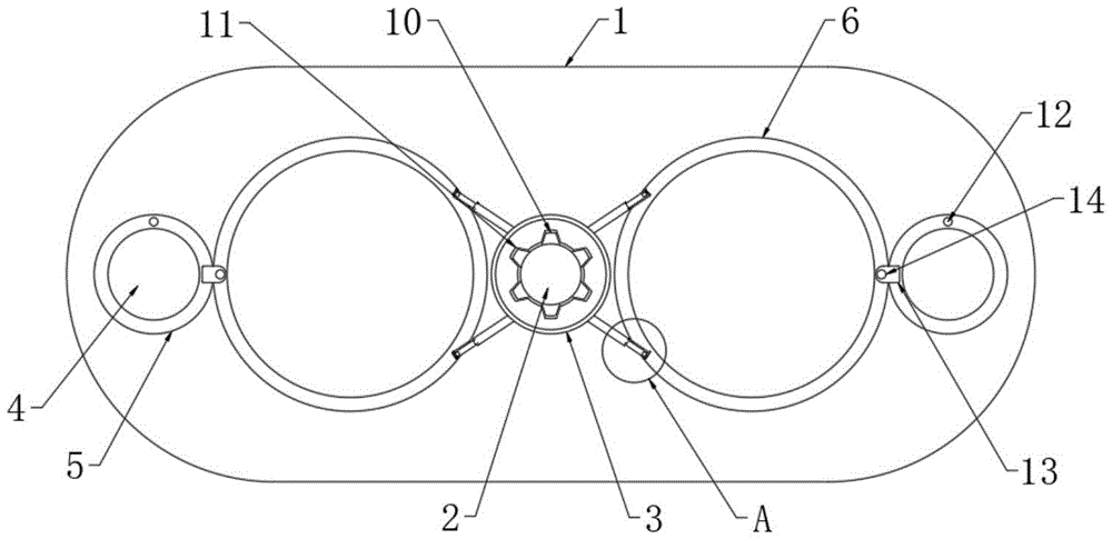
图1为本实用新型提出的一种电子芯片测试探针台旋转升降机构的俯视结构示意图;Fig. 1 is the top-view structure schematic diagram of a kind of electronic chip testing probe station rotary lifting mechanism proposed by the utility model;
图2为图1的A处结构放大示意图;Fig. 2 is the enlarged schematic diagram of the structure at A of Fig. 1;
图3为本实用新型提出的一种电子芯片测试探针台旋转升降机构的传动机构结构示意图。3 is a schematic structural diagram of a transmission mechanism of a rotary lifting mechanism for an electronic chip test probe station proposed by the present invention.
图中:1底座、2转动杆、3套环、4螺纹杆、5螺母、6探针台、7衔接杆、8衔接槽、9第一连接孔、10凸条、11凹槽、12限制杆、13限位板、14固定螺栓、15腔体、16第一驱动电机、17第二驱动电机。In the picture: 1 base, 2 rotating rod, 3 collar, 4 threaded rod, 5 nut, 6 probe station, 7 connecting rod, 8 connecting groove, 9 first connecting hole, 10 convex strip, 11 groove, 12 limit Rod, 13 limiting plate, 14 fixing bolt, 15 cavity, 16 first drive motor, 17 second drive motor.
具体实施方式Detailed ways
下面将结合本实用新型实施例中的附图,对本实用新型实施例中的技术方案进行清楚、完整地描述,显然,所描述的实施例仅仅是本实用新型一部分实施例,而不是全部的实施例。The technical solutions in the embodiments of the present utility model will be clearly and completely described below with reference to the accompanying drawings in the embodiments of the present utility model. Obviously, the described embodiments are only a part of the embodiments of the present utility model, rather than all the implementations. example.
在本实用新型的描述中,需要理解的是,术语“上”、“下”、“前”、“后”、“左”、“右”、“顶”、“底”、“内”、“外”等指示的方位或位置关系为基于附图所示的方位或位置关系,仅是为了便于描述本实用新型和简化描述,而不是指示或暗示所指的装置或元件必须具有特定的方位、以特定的方位构造和操作,因此不能理解为对本实用新型的限制。In the description of the present invention, it should be understood that the terms "upper", "lower", "front", "rear", "left", "right", "top", "bottom", "inside", The orientation or positional relationship indicated by "outside" is based on the orientation or positional relationship shown in the accompanying drawings, which is only for the convenience of describing the present invention and simplifying the description, rather than indicating or implying that the indicated device or element must have a specific orientation , are constructed and operated in a specific orientation, and therefore should not be construed as a limitation of the present invention.
参照图1-3,一种电子芯片测试探针台旋转升降机构,包括底座1,底座1上端面转动连接有一根转动杆2与两根螺纹杆4,转动杆2外壁套设有套环3,套环3通过限制机构与转动杆2连接,限制机构多条固定于转动杆2外壁的凸条10,套环3内壁设有多个与凸条10对应的凹槽11,转动杆2外壁固定有用于支撑套环3的支撑环,套环3在凸条10以及凹槽11的限制下会跟随转动杆2一起转动,还可以相对于转动杆2上下移动且不转动,其中支撑环用于支撑套环3给予其初始高度。Referring to Figures 1-3, an electronic chip test probe station rotating and lifting mechanism includes a
底座1上方设有两个位于转动杆2两侧的探针台6,两个探针台6均通过衔接机构与套环3连接,衔接机构包括多条固定于套环3外壁的衔接杆7,探针台6外壁设有与衔接杆7对应的衔接槽8,探针台6端面螺纹连接有延伸至衔接槽8内的紧固螺栓,衔接杆7上设有与紧固螺栓配合的第一连接孔9,衔接杆7处于衔接槽8中,紧固螺栓末端处于第一连接孔9中,探针台6会实现与套环3的连接。There are two
两根螺纹杆4外壁均螺纹套设有螺母5,螺母5上下端面均固定有限位板13,限位板13上设有与探针台6对应的固定机构,固定机构包括螺纹连接在限位板13上的固定螺栓14,探针台6上端面设有与固定螺栓14配合的第二连接孔,当探针台6上下端面处于两个限位板13之间,且固定螺栓14与第二连接孔螺纹连接上的时候,即可实现与螺母5的连接。The outer walls of the two threaded
底座1内部设有腔体15,两根螺纹杆4端部均与腔体15内底壁转动连接,腔体15内设有与转动杆2配合的第一驱动电机16,腔体15内还设有与其中一根螺纹杆4连接的第二驱动电机17,两根螺纹杆4之间通过传动机构连接,传动机构包括固定于两根螺纹杆4外壁的传动皮带轮,两个传动皮带轮之间通过连接皮带连接,关闭第一驱动电机16并启动第二驱动电机17,第二驱动电机17可以直接带动其中一根螺纹杆4转动,在传动皮带轮与连接皮带的作用下还可以带动另外一根螺纹杆4转动。The
底座1上端面固定有两根限制杆12,两根限制杆12均滑动贯穿螺母5,限制杆12是为了限制螺母5的,避免螺母5跟随螺纹杆4一起转动,从而实现升降操作。Two
本实用新型使用时,正常状态下,探针台6不与螺母5连接,此时启动第一驱动电机16,第一驱动电机16可以直接带动转动杆2转动,转动杆2转动的时候其外壁套设的套环3可以跟随转动杆2转动,从而通过衔接杆7带动与其连接的探针台6实现转动功能;When the utility model is used, under normal conditions, the
当探针台6上下端面处于两个限位板13之间,且固定螺栓14与第二连接孔螺纹连接上的时候,关闭第一驱动电机16并启动第二驱动电机17,第二驱动电机17可以直接带动其中一根螺纹杆4转动,在传动皮带轮与连接皮带的作用下还可以带动另外一根螺纹杆4转动,此时探针台6、衔接杆7与套环3为一体,可以跟随螺母5相对于螺纹杆4完成上升操作,此时的套环3处于转动杆2外壁上升滑动;When the upper and lower end surfaces of the
探针台6与套环3之间的连接依靠衔接杆7,衔接杆7处于衔接槽8中依靠紧固螺栓实现连接,拆卸掉紧固螺栓后即可解除衔接杆7与探针台6的连接,从而实现对探针台6的拆卸。The connection between the
以上所述,仅为本实用新型较佳的具体实施方式,但本实用新型的保护范围并不局限于此,任何熟悉本技术领域的技术人员在本实用新型揭露的技术范围内,根据本实用新型的技术方案及其实用新型构思加以等同替换或改变,都应涵盖在本实用新型的保护范围之内。The above description is only a preferred embodiment of the present invention, but the protection scope of the present invention is not limited to this. Equivalent replacement or modification of the new technical solution and its utility model concept shall be included within the protection scope of the present utility model.
Claims (6)
Priority Applications (1)
| Application Number | Priority Date | Filing Date | Title |
|---|---|---|---|
| CN202220301166.7U CN217543162U (en) | 2022-02-15 | 2022-02-15 | An electronic chip test probe station rotary lifting mechanism |
Applications Claiming Priority (1)
| Application Number | Priority Date | Filing Date | Title |
|---|---|---|---|
| CN202220301166.7U CN217543162U (en) | 2022-02-15 | 2022-02-15 | An electronic chip test probe station rotary lifting mechanism |
Publications (1)
| Publication Number | Publication Date |
|---|---|
| CN217543162U true CN217543162U (en) | 2022-10-04 |
Family
ID=83425493
Family Applications (1)
| Application Number | Title | Priority Date | Filing Date |
|---|---|---|---|
| CN202220301166.7U Expired - Fee Related CN217543162U (en) | 2022-02-15 | 2022-02-15 | An electronic chip test probe station rotary lifting mechanism |
Country Status (1)
| Country | Link |
|---|---|
| CN (1) | CN217543162U (en) |
-
2022
- 2022-02-15 CN CN202220301166.7U patent/CN217543162U/en not_active Expired - Fee Related
Similar Documents
| Publication | Publication Date | Title |
|---|---|---|
| CN105047575B (en) | An inclined block lifting mechanism for wafer testing | |
| CN110828326A (en) | Intensity detection device for photovoltaic silicon wafers | |
| CN217543162U (en) | An electronic chip test probe station rotary lifting mechanism | |
| CN217384519U (en) | Medical treatment bearing drive torque test fixture | |
| CN218411020U (en) | Fitment is with roughness detection machine | |
| CN216593329U (en) | Elevator door flatness detection device | |
| CN215910595U (en) | Probe pin testing device of integrated circuit testing seat | |
| CN218064093U (en) | A convenient mobile construction engineering environment monitoring equipment | |
| CN210571109U (en) | Torque testing tool for permanent magnet synchronous motor | |
| CN224019856U (en) | A support device for needle card maintenance | |
| CN212006982U (en) | A kind of flange rotation hole detection device | |
| CN212514889U (en) | Electronic chip detection device | |
| CN217639167U (en) | Wafer probe station connecting mechanism | |
| CN208568443U (en) | A kind of construction material hardness ability to bear detection device | |
| CN211602834U (en) | Engineering is supervised and is used impervious appearance of concrete test block | |
| CN218565031U (en) | Silicon steel strip slitting line swing arm detection device for transformer production | |
| CN221854179U (en) | A detachable structure of a lifting platform for counterweight gravity energy storage that is easy to inspect and repair | |
| CN215037270U (en) | A chip testing equipment lifting and rotating platform module | |
| CN212871171U (en) | Key groove symmetry measuring device | |
| CN223305688U (en) | Underground steel wire fishing device for petroleum drilling | |
| CN219571361U (en) | Multi-dimensional detection device of 5G communication terminal | |
| CN223346430U (en) | Movable upright post lifting test tool | |
| CN218658055U (en) | Machine tool transmission device with good stability | |
| CN221550729U (en) | Chip positioning and testing device | |
| CN222188127U (en) | Outer diameter detection equipment for automobile transmission shaft |
Legal Events
| Date | Code | Title | Description |
|---|---|---|---|
| GR01 | Patent grant | ||
| GR01 | Patent grant | ||
| CF01 | Termination of patent right due to non-payment of annual fee | ||
| CF01 | Termination of patent right due to non-payment of annual fee |
Granted publication date: 20221004 |