CN217500279U - Foundation pit siphon dewatering structure provided with semi-closed check valve - Google Patents
Foundation pit siphon dewatering structure provided with semi-closed check valve Download PDFInfo
- Publication number
- CN217500279U CN217500279U CN202221425915.3U CN202221425915U CN217500279U CN 217500279 U CN217500279 U CN 217500279U CN 202221425915 U CN202221425915 U CN 202221425915U CN 217500279 U CN217500279 U CN 217500279U
- Authority
- CN
- China
- Prior art keywords
- siphon
- water
- semi
- valve
- check valve
- Prior art date
- Legal status (The legal status is an assumption and is not a legal conclusion. Google has not performed a legal analysis and makes no representation as to the accuracy of the status listed.)
- Active
Links
Images


Classifications
-
- Y—GENERAL TAGGING OF NEW TECHNOLOGICAL DEVELOPMENTS; GENERAL TAGGING OF CROSS-SECTIONAL TECHNOLOGIES SPANNING OVER SEVERAL SECTIONS OF THE IPC; TECHNICAL SUBJECTS COVERED BY FORMER USPC CROSS-REFERENCE ART COLLECTIONS [XRACs] AND DIGESTS
- Y02—TECHNOLOGIES OR APPLICATIONS FOR MITIGATION OR ADAPTATION AGAINST CLIMATE CHANGE
- Y02A—TECHNOLOGIES FOR ADAPTATION TO CLIMATE CHANGE
- Y02A20/00—Water conservation; Efficient water supply; Efficient water use
Abstract
The utility model discloses a set up foundation ditch siphon precipitation structure of semi-enclosed check valve belongs to foundation ditch precipitation field. The structure comprises a siphon pipe, a semi-closed check valve, a water collecting tank and a water injection device; the siphon comprises a first port and a second port, the first port is located in the precipitation well, the second port is located in the water collecting tank, a semi-closed check valve is arranged at the first port, a plurality of capillary holes which are permeable to air and water are formed in a valve block of the semi-closed check valve, and a water injection device which is used for injecting water into the siphon is arranged on the siphon close to the second port. The utility model discloses a set up semi-closed check valve in first port department, when the siphon started, can effectively prevent the reverse flow of water, nevertheless allow the air freely to pass through, exhaust efficiency is high, and the siphon starts soon. This semi-closed check valve still includes the filter, has the function of filtering the fine particle, and the filter screen of different density is selected in a flexible way to the convenient filtration requirement according to the difference, prevents that foundation ditch precipitation from arousing soil erosion and water loss.
Description
Technical Field
The utility model belongs to foundation ditch precipitation field, concretely relates to set up foundation ditch siphon precipitation structure of semi-enclosed check valve.
Background
The siphon needs water injection and exhaust to start, and common siphon starting method has the reverse water injection of delivery port and the start of delivery port pumping, and in the foundation ditch siphon precipitation structure, the siphon starts at the reverse water injection of delivery port and exhausts, and the water inlet installation check valve prevents to leak, and gas-liquid mixes in the pipe, and exhaust efficiency is slower.
For example, the chinese utility model with application number 201020604288.0 discloses a siphon type flood discharge device, which comprises a siphon system and a bracket; the siphon system comprises a water suction pipe provided with a check valve, a horizontal pipe, a water drain pipe provided with a third valve and a water adding and exhausting pipe; the water level alarm device is characterized in that the check valve is positioned at a water inlet of the water suction pipe, the water suction pipe extends into water below a water level alarm line, two ends of the horizontal pipe are respectively connected with the water suction pipe and the water drain pipe through elbows, the water adding and exhausting pipe is connected with the horizontal pipe through a tee joint, and a first valve and a second valve are arranged on the water adding and exhausting pipe. Although this technical scheme can adopt a plurality of this devices flood discharge simultaneously, the conventional check valve of adoption can lead to absorbing the gas-liquid mixture in the pipe, and easy siphon starts the failure.
Therefore, it is highly desirable to provide a new siphon dewatering structure for foundation pit.
SUMMERY OF THE UTILITY MODEL
An object of the utility model is to overcome the defect among the prior art to a foundation ditch siphon precipitation structure who sets up semi-enclosed check valve is provided.
The utility model discloses the concrete technical scheme who adopts as follows:
the utility model provides a foundation pit siphon dewatering structure provided with a semi-closed check valve, which comprises a siphon, a semi-closed check valve, a water collecting tank and a water injection device;
the water collecting tank is arranged on the inner side of the foundation pit, and the dewatering well positioned outside the foundation pit can discharge water flow to the water collecting tank through the siphon action of the siphon pipe; the siphon is including being located the first port in the precipitation well and being located the second port of header tank, and first port department is equipped with semi-closed check valve, has seted up a plurality of capillary holes that permeate water a little of breathing freely on the valve block of semi-closed check valve, is equipped with the water injection device that is used for the intraductal water injection of siphon on the siphon of neighbouring second port department.
Preferably, a drainage device for draining water out of the foundation pit is further arranged in the water collection tank.
Preferably, the water level in the water collecting tank is always lower than the water level in the dewatering well.
Preferably, the first port of the siphon is located at the position which is not less than 1m below the lowest precipitation water level in the precipitation well, and the second port is located at the position which is not less than 1m below the water level in the water collecting tank.
Preferably, the semi-closed check valve comprises a valve body, a valve plate, a first positioning piece and a second positioning piece; the first valve port at the top of the valve body is connected with the siphon, and the second valve port at the bottom is used for directly contacting with the water body in the dewatering well; a first positioning piece, a valve plate and a second positioning piece are coaxially arranged in the valve body in a direction perpendicular to the water flow direction, and the first positioning piece and the second positioning piece are fixed in the valve body and can enable water flow to pass through; the center of the valve block is fixedly connected with a guide rod, two ends of the guide rod are respectively located in a first positioning hole of the first positioning piece and a second positioning hole of the second positioning piece, and the guide rod can drive the valve block to move between the first positioning piece and the second positioning piece under the limiting effect of the first positioning hole and the second positioning hole so as to realize the opening and closing of the semi-closed check valve.
Furthermore, the first positioning piece is fixed in the valve cavity, the main body is of an annular structure, and the first positioning hole is coaxially arranged in the main body and is fixedly connected with the main body through a plurality of first supporting pieces; the second positioning piece is fixed at a second valve port of the semi-closed check valve, the main body is of an annular structure, and the second positioning hole is coaxially arranged in the main body and is fixedly connected with the main body through a plurality of second supporting pieces; the cross-sectional dimension of the valve plate is larger than the second positioning piece and smaller than the first positioning piece.
Further, the valve body is separated at the first positioning sheet and the second positioning sheet and is connected through threads; and a gasket for increasing the sealing property is fixed on the lower and outer edges of the valve plate in the circumferential direction.
Furthermore, a filter is detachably connected to a second valve opening of the semi-closed check valve.
Still further, the filter comprises a filter framework, a filter screen and a binding wire, wherein the filter screen is wrapped and fixed outside the filter framework through the binding wire.
Preferably, the water injection device comprises a three-way joint, a drain valve and a water injection valve; the first pipe orifice and the second pipe orifice of the three-way joint are both connected to the siphon, the second pipe orifice located below is provided with a drain valve used for controlling whether the siphon is communicated with the water collecting tank, and the third pipe orifice is connected with an external pressure water source through a water injection valve used for controlling whether water is injected.
Compared with the prior art, the utility model, following beneficial effect has:
the utility model discloses a set up semi-closed check valve in first port department, when the siphon started, can effectively prevent the reverse flow of water, nevertheless allow the air freely to pass through, exhaust efficiency is high, and the siphon starts soon. This semi-closed check valve still includes the filter, has the function of filtering the fine particle, and the filter screen of different density is selected in a flexible way to the convenient filtration requirement according to the difference, prevents that foundation ditch precipitation from arousing soil erosion and water loss.
Drawings
FIG. 1 is a schematic diagram of a siphon dewatering structure of a foundation pit with a semi-closed check valve;
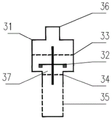
FIG. 2 is a schematic cross-sectional view of a semi-closed check valve;
FIG. 3 is a schematic diagram illustrating an open state of the semi-hermetic check valve;
FIG. 4 is a schematic view of a closed state of the semi-hermetic check valve;
FIG. 5 is an exploded view of a semi-enclosed check valve configuration;
FIG. 6 is a schematic view of the first positioning member;
FIG. 7 is a schematic view of a second positioning member;
FIG. 8 is a schematic view of a filter construction;
FIG. 9 is a schematic view of the structure of the water injection device;
FIG. 10 is a schematic view of the exhaust state of a foundation pit siphon dewatering structure with a semi-closed check valve at the water inlet;
FIG. 11 is a schematic diagram of a drainage state of a foundation pit siphon dewatering structure with a semi-closed check valve at a water inlet;
the reference numbers in the figures are: the device comprises a precipitation well 1, a siphon 2, a semi-closed check valve 3, a valve body 31, a valve plate 32, a first positioning piece 33, a first positioning hole 331, a first supporting piece 332, a second positioning piece 34, a second positioning hole 341, a second supporting piece 342, a filter 35, a filter framework 351, a filter screen 352, a binding wire 353, a first valve port 36, a second valve port 37, a water collecting tank 4, a drainage device 5, a water injection device 6, a three-way joint 61, a drainage valve 62, a water injection valve 63 and a foundation pit enclosure structure 7.
Detailed Description
The invention will be further elucidated and described with reference to the drawings and embodiments. The utility model discloses in the technical characteristics of each embodiment under the prerequisite that does not conflict each other, all can carry out corresponding combination.
Because conventional foundation ditch siphon precipitation structure when the siphon starts the water injection exhaust, gas-liquid mixture in the pipe, exhaust efficiency is slower, consequently the utility model provides a water inlet sets up the foundation ditch siphon precipitation structure of semi-enclosed check valve. This foundation ditch siphon precipitation structure can realize starting the water injection when exhausting at the siphon, prevents the reverse flow of water, but allows the free circulation of air, improves the carminative efficiency of water injection. The concrete components and connection mode of the foundation pit siphon precipitation structure of the present invention will be described below.
As shown in fig. 1, for the utility model provides a pair of set up semi-closed check valve's foundation ditch siphon precipitation structure, it mainly includes siphon 2, semi-closed check valve 3, header tank 4 and water injection device 6.
The utility model discloses an among the foundation ditch siphon precipitation structure, precipitation well 1 sets up in the foundation ditch outside, and header tank 4 sets up in the foundation ditch inboard, and precipitation well 1 and header tank 4 pass through siphon 2 intercommunication. The water level in the water collecting tank is always lower than that in the dewatering well so as to ensure the successful siphon action. Specifically, siphon 2 is including being located the first port of precipitation well 1 and being located the second port of header tank 4, and the first port of siphon is located the precipitation well, and should be no less than 1m below the minimum precipitation water level to along with the going on of suction process, the water level reduces gradually in the precipitation well and leads to the first port of siphon to expose the surface of water, influences the going on smoothly of suction process. The second port of the siphon is located in the water collection tank and should be no less than 1m below the water level of the water collection tank. In order to facilitate the regular drainage of the water collecting tank 4, a set of drainage device 5 can be additionally arranged in the water collecting tank 4, and the water collected in the water collecting tank 4 can be regularly drained outside the foundation pit through the drainage device 5, so that the continuous operation of the foundation pit siphon dewatering structure is ensured. And a foundation pit enclosing structure 7 is also arranged in the circumferential direction of the foundation pit.
The semi-closed check valve 3 is arranged at the first port of the siphon 2, the valve plate 32 of the semi-closed check valve 3 is provided with a plurality of air-permeable, micro-permeable capillary holes, the reverse flow of water can be effectively prevented through the semi-closed check valve 3, but air is allowed to freely flow, and the water injection and exhaust efficiency is improved. In practical application, the diameter of the capillary hole is generally below 1mm, so as to realize the effect of air permeability and micro water permeability. The utility model provides a ventilative little permeable to water indicates, allows gaseous through the capillary hole, but the water is best not to pass through, that is to say, the most ideal state of valve block only allows gaseous through, not allow the water to pass through, but if some water also can, can not show the influence the utility model discloses the realization of functional effect. The utility model discloses distribute the capillary hole on semi-enclosed check valve block, because capillary tension, rivers can't pass through or permeate water a little, and gas can freely pass, is used in the siphon starts the water injection and exhausts and can improves carminative efficiency.
In this embodiment, the structure of the semi-hermetic check valve 3 is shown in fig. 2. The semi-closed check valve 3 comprises a valve body 31, a valve plate 32, a first positioning part 33 and a second positioning part 34. The first valve port 36 at the top of the valve body 31 is connected with the siphon 2, and the second valve port 37 at the bottom is used for directly contacting with the water body in the precipitation well 1. The valve body 31 is coaxially provided with a first positioning member 33, a valve plate 32 and a second positioning member 34 in a direction perpendicular to the water flow direction, and the first positioning member 33 and the second positioning member 34 are fixed in the valve body 31 and can allow water to pass through. The center of the valve sheet 32 is fixedly connected with a guide rod, two ends of the guide rod are respectively located in the first positioning hole 331 of the first positioning element 33 and the second positioning hole 341 of the second positioning element 34, the guide rod and the first positioning hole 331 and the second positioning hole 341 form sliding connection, and the guide rod can drive the valve sheet 32 to move between the first positioning element 33 and the second positioning element 34 under the limiting effect of the first positioning hole 331 and the second positioning hole 341 so as to realize the opening and closing of the semi-closed check valve 3.
Specifically, as shown in fig. 6, the first positioning member 33 is fixed in the valve cavity, the main body is an annular structure, and the first positioning hole 331 is coaxially disposed inside the main body and fixedly connected thereto by a plurality of first supporting members 332; as shown in fig. 7, the second positioning element 34 is fixed at the second port 37 of the semi-closed check valve 3, the main body is an annular structure, and the second positioning hole 341 is coaxially disposed inside the main body and is fixedly connected to the main body through a plurality of second supporting elements 342. The flow area in the valve body should be larger than the cross-sectional area of the siphon tube, and the cross-sectional size of the valve plate 32 should be larger than the second positioning member 34 and smaller than the first positioning member 33, so that when the valve plate 32 moves to the second positioning member 34, as shown in fig. 4, the valve is in a closed state, gas can flow at this time, but the water body can hardly pass through the valve plate; when the valve plate 32 moves to the first positioning member 33, as shown in fig. 3, the valve is in an open state, and both gas and water can flow through.
To facilitate the installation and replacement of the first positioning member 33 and the second positioning member 34, the valve body 31 may be separated at the first positioning member 33 and the second positioning member 34 and screwed, as shown in fig. 5. In order to ensure a better sealing effect, a gasket for increasing the sealing property can be fixed on the lower portion and the outer portion of the valve plate 32 along the circumferential direction.
In addition, in order to prevent water and soil loss caused in the process of pumping the foundation pit precipitation, a filter 35 can be detachably connected to a second valve port 37 of the semi-closed check valve 3, and the filter 35 and the semi-closed check valve 3 can be in threaded connection. As shown in fig. 8, the filter 35 is mainly used for filtering fine particles, and includes a filter frame 351, a filter screen 352 and a binding wire 353, wherein the filter screen 352 is wrapped and fixed outside the filter frame 351 by the binding wire 353. The filter screen can change the filter screen of different density according to actual conditions is nimble, has broken also conveniently to take out and replaces the restoration, and fine particle protection effect is better.
A water injection device 6 is arranged on the siphon pipe 2 adjacent to the second port of the siphon pipe 2, and the water injection device 6 is used for injecting water into the siphon pipe 2. In this embodiment, the water filling device 6 may adopt a structure as shown in fig. 9, and specifically includes a three-way joint 61, a drain valve 62, and a water filling valve 63. The first pipe orifice and the second pipe orifice of the three-way joint 61 are both connected to the siphon 2, the second pipe orifice located below is provided with a drain valve 62 for controlling whether the siphon 2 is communicated with the water collecting tank 4, and the third pipe orifice is connected with an external pressure water source through a water injection valve 63 for controlling whether water is injected.
Utilize above-mentioned foundation ditch siphon precipitation structure's exhaust and drainage process, specifically as follows:
before using at first right the utility model discloses a semi-closed check valve assembles: the guide arm of valve block aims at first setting element and second setting element and puts into the inner chamber of valve body, then screws up the screw thread on the valve body, selects the filter screen parcel of suitable density around the filter skeleton, then fixes with the bundle silk, accomplishes the back, with the lower extreme of filter installation check valve water inlet. The semi-closed check valve is installed at the first port of the siphon.
During air exhaust, the water discharge valve is closed, the water injection valve is opened, reverse water injection and air exhaust are performed on the siphon, in the reverse water injection process, the valve plate is pushed downwards by downward water pressure to close the second valve port 37 at the bottom of the check valve, water flow cannot flow reversely, and air can freely flow through capillary holes in the valve plate, as shown in fig. 10. After water injection and exhaust are completed, the water injection valve is closed, the water outlet valve is opened, the liquid level difference between the first port and the second port of the siphon tube can generate upward water pressure, the valve plate is further pushed upwards to the position of the first positioning plate, the second port 37 at the bottom of the check valve is opened, water flows through the second port 37 of the check valve and the through hole on the outer side of the valve plate, siphon is started, and water is discharged from the dewatering well, as shown in fig. 11.
The above-mentioned embodiments are merely a preferred embodiment of the present invention, but it is not intended to limit the present invention. Various changes and modifications can be made by one of ordinary skill in the pertinent art without departing from the spirit and scope of the present invention. Therefore, all the technical schemes obtained by adopting the mode of equivalent replacement or equivalent transformation fall within the protection scope of the utility model.
Claims (10)
1. A foundation pit siphon dewatering structure provided with a semi-closed check valve is characterized by comprising a siphon pipe (2), a semi-closed check valve (3), a water collecting tank (4) and a water injection device (6);
the water collecting tank (4) is arranged on the inner side of the foundation pit, and the dewatering well (1) positioned outside the foundation pit can discharge water flow to the water collecting tank (4) through the siphoning effect of the siphon (2); siphon (2) including being located the first port of precipitation well (1) and being located the second port of header tank (4), first port department is equipped with semi-enclosed check valve (3), has seted up a plurality of capillary holes that permeate water a little of breathing freely on valve block (32) of semi-enclosed check valve (3), is equipped with water injection device (6) that are used for to water injection in siphon (2) on siphon (2) of neighbouring second port department.
2. The foundation pit siphon dewatering structure provided with the semi-closed check valve as claimed in claim 1, characterized in that a drainage device (5) for draining water out of the foundation pit is further arranged in the water collection tank (4).
3. The foundation pit siphon dewatering structure provided with the semi-closed check valve according to claim 1, characterized in that the water level in the water collecting tank (4) is always lower than the water level in the dewatering well (1).
4. The foundation pit siphon precipitation structure provided with the semi-closed check valve as claimed in claim 1, wherein the first port of the siphon (2) is located no less than 1m below the lowest precipitation water level in the precipitation well (1), and the second port is located no less than 1m below the water level in the water collection tank (4).
5. The foundation pit siphon dewatering structure provided with the semi-closed check valve according to claim 1, characterized in that the semi-closed check valve (3) comprises a valve body (31), a valve plate (32), a first positioning part (33) and a second positioning part (34); a first valve port (36) at the top of the valve body (31) is connected with the siphon (2), and a second valve port (37) at the bottom is used for directly contacting with the water body in the precipitation well (1); a first positioning piece (33), a valve plate (32) and a second positioning piece (34) are coaxially arranged in the valve body (31) and perpendicular to the water flow direction, and the first positioning piece (33) and the second positioning piece (34) are fixed in the valve body (31) and can enable water flow to pass through; the center of valve block (32) fixedly connected with guide arm, the guide arm both ends are arranged in first locating hole (331) of first locating piece (33) and second locating hole (341) of second locating piece (34) respectively, and the guide arm can drive valve block (32) under the limiting displacement of first locating hole (331) and second locating hole (341) and move between first locating piece (33) and second locating piece (34) in order to realize opening and closing of semi-enclosed check valve (3).
6. The foundation pit siphon dewatering structure provided with the semi-closed check valve, as claimed in claim 5, wherein the first positioning member (33) is fixed in the valve cavity, the main body is of an annular structure, and the first positioning hole (331) is coaxially arranged inside the main body and fixedly connected with the main body through a plurality of first supporting members (332); the second positioning piece (34) is fixed at a second valve port (37) of the semi-closed check valve (3), the main body is of an annular structure, and the second positioning hole (341) is coaxially arranged in the main body and is fixedly connected with the main body through a plurality of second supporting pieces (342); the cross-sectional dimension of the valve plate (32) is larger than the second positioning piece (34) and smaller than the first positioning piece (33).
7. The foundation pit siphon water lowering structure provided with the semi-closed check valve is characterized in that the valve body (31) is separated at the first positioning part (33) and the second positioning part (34) and is connected through threads; a gasket used for increasing the sealing performance is fixed on the lower outer edge of the valve plate (32) in the circumferential direction.
8. The foundation pit siphon water lowering structure provided with the semi-closed check valve as claimed in claim 5, wherein a filter (35) is detachably connected to the second valve port (37) of the semi-closed check valve (3).
9. The foundation pit siphon dewatering structure provided with the semi-closed check valve as claimed in claim 8, wherein the filter (35) comprises a filter framework (351), a filter screen (352) and a binding wire (353), and the filter screen (352) is fixed to the outside of the filter framework (351) through the binding wire (353) in a wrapping mode.
10. The foundation pit siphon dewatering structure provided with the semi-closed check valve as claimed in claim 1, wherein the water injection device (6) comprises a three-way joint (61), a water discharge valve (62) and a water injection valve (63); the first mouth of pipe and the second mouth of pipe of three way connection (61) all connect on siphon (2), and the second mouth of pipe department that is located the below is equipped with and is used for controlling whether drainage valve (62) that siphon (2) and header tank (4) communicate, and the third mouth of pipe links to each other with external pressure water source through water injection valve (63) that are used for controlling whether water injection.
Priority Applications (1)
| Application Number | Priority Date | Filing Date | Title |
|---|---|---|---|
| CN202221425915.3U CN217500279U (en) | 2022-06-06 | 2022-06-06 | Foundation pit siphon dewatering structure provided with semi-closed check valve |
Applications Claiming Priority (1)
| Application Number | Priority Date | Filing Date | Title |
|---|---|---|---|
| CN202221425915.3U CN217500279U (en) | 2022-06-06 | 2022-06-06 | Foundation pit siphon dewatering structure provided with semi-closed check valve |
Publications (1)
| Publication Number | Publication Date |
|---|---|
| CN217500279U true CN217500279U (en) | 2022-09-27 |
Family
ID=83360406
Family Applications (1)
| Application Number | Title | Priority Date | Filing Date |
|---|---|---|---|
| CN202221425915.3U Active CN217500279U (en) | 2022-06-06 | 2022-06-06 | Foundation pit siphon dewatering structure provided with semi-closed check valve |
Country Status (1)
| Country | Link |
|---|---|
| CN (1) | CN217500279U (en) |
Cited By (1)
| Publication number | Priority date | Publication date | Assignee | Title |
|---|---|---|---|---|
| CN117306564A (en) * | 2023-11-24 | 2023-12-29 | 牡丹区公路事业发展中心 | Environment-friendly grass planting concrete highway slope protection system |
-
2022
- 2022-06-06 CN CN202221425915.3U patent/CN217500279U/en active Active
Cited By (1)
| Publication number | Priority date | Publication date | Assignee | Title |
|---|---|---|---|---|
| CN117306564A (en) * | 2023-11-24 | 2023-12-29 | 牡丹区公路事业发展中心 | Environment-friendly grass planting concrete highway slope protection system |
Similar Documents
| Publication | Publication Date | Title |
|---|---|---|
| CN217500279U (en) | Foundation pit siphon dewatering structure provided with semi-closed check valve | |
| CN212631874U (en) | Ejecting type filtering sand cylinder | |
| CN205886376U (en) | Special filter of swimming pool | |
| CN202010458U (en) | Fiber ball filtering tank | |
| CN210216346U (en) | Gate with filtering device | |
| CN209392837U (en) | Ceramic membrane and porcelain sand bilayer filter | |
| CN208532385U (en) | A kind of up-flow integrated sewage treating apparatus | |
| CN208482117U (en) | A kind of sewage disposal device with multistage filtering function | |
| CN207324262U (en) | A kind of novel double-layer water filter | |
| CN220609347U (en) | Integrated air-water backwashing energy-saving water purifying equipment | |
| CN219149498U (en) | Outdoor portable water filter | |
| CN2843600Y (en) | Membrane filter | |
| CN115162388B (en) | Foundation pit parallel siphon dewatering device and dewatering construction method | |
| CN215712169U (en) | Environment-friendly sewage treatment device | |
| CN215137359U (en) | Wastewater resin trapper for fine treatment and regeneration | |
| CN220224754U (en) | Paper pulp filtering device for paper pulp tank | |
| CN218530019U (en) | Water intaking infiltration canal silt filter equipment | |
| CN220070876U (en) | Backflushing siphon filter device | |
| CN215566857U (en) | Exhaust pipe structure for air suspension fan | |
| CN216075334U (en) | Integrated water supply equipment | |
| CN207085526U (en) | A kind of siphoning installation of valveless water filter device | |
| CN219825154U (en) | Irrigation equipment for preventing flood and draining waterlogging | |
| CN214437175U (en) | Automatic frequency conversion backwashing combined filter | |
| CN215048898U (en) | Fully-sealed high-level clear water tank | |
| CN208990357U (en) | A kind of filter device applied to wastewater treatment |
Legal Events
| Date | Code | Title | Description |
|---|---|---|---|
| GR01 | Patent grant | ||
| GR01 | Patent grant |