CN217482638U - Portable ceiling lamp - Google Patents
Portable ceiling lamp Download PDFInfo
- Publication number
- CN217482638U CN217482638U CN202221701948.6U CN202221701948U CN217482638U CN 217482638 U CN217482638 U CN 217482638U CN 202221701948 U CN202221701948 U CN 202221701948U CN 217482638 U CN217482638 U CN 217482638U
- Authority
- CN
- China
- Prior art keywords
- base
- ceiling lamp
- wire
- battery
- driving circuit
- Prior art date
- Legal status (The legal status is an assumption and is not a legal conclusion. Google has not performed a legal analysis and makes no representation as to the accuracy of the status listed.)
- Active
Links
Images


Classifications
-
- Y—GENERAL TAGGING OF NEW TECHNOLOGICAL DEVELOPMENTS; GENERAL TAGGING OF CROSS-SECTIONAL TECHNOLOGIES SPANNING OVER SEVERAL SECTIONS OF THE IPC; TECHNICAL SUBJECTS COVERED BY FORMER USPC CROSS-REFERENCE ART COLLECTIONS [XRACs] AND DIGESTS
- Y02—TECHNOLOGIES OR APPLICATIONS FOR MITIGATION OR ADAPTATION AGAINST CLIMATE CHANGE
- Y02B—CLIMATE CHANGE MITIGATION TECHNOLOGIES RELATED TO BUILDINGS, e.g. HOUSING, HOUSE APPLIANCES OR RELATED END-USER APPLICATIONS
- Y02B20/00—Energy efficient lighting technologies, e.g. halogen lamps or gas discharge lamps
- Y02B20/40—Control techniques providing energy savings, e.g. smart controller or presence detection
Abstract
The utility model relates to the technical field of lamps, in particular to a portable ceiling lamp, which comprises a base; the heat dissipation substrate is fixedly arranged at the central position of the base; the wire bundling box is arranged at the edge position of the base, one side of the wire bundling box is provided with a line inlet, and the other side of the wire bundling box is provided with a line outlet; the wire connector is arranged at the edge position of the base; the light source assembly comprises a light-emitting assembly, a driving circuit assembly and a wire connector, wherein the light-emitting assembly is attached to and fixedly arranged at the upper end of the heat dissipation substrate, the driving circuit assembly is arranged in the wire bunching box, one end of a wire of the driving circuit assembly is connected with the light-emitting assembly, and the other end of the wire of the driving circuit assembly is connected with an external power supply through the wire connector; the lamp shade is sleeved on the edge of the base and is detachably connected with the base. Through the design to the base, with the reasonable setting of bunch box and connector in base department, simple to operate is simple, and the wiring is quick, and whole lamps and lanterns design is simple, the sexual valence relative altitude.
Description
Technical Field
The utility model belongs to the technical field of the lamps and lanterns technique and specifically relates to indicate a portable ceiling lamp.
Background
The ceiling lamp is one of lamps, and the ceiling lamp is called as the ceiling lamp as the name suggests because the lamp top is relatively flat, and the bottom pastes on the roof completely during installation. The light source includes a common white bulb, a fluorescent lamp, a high-intensity gas discharge lamp, a halogen tungsten lamp, an LED, etc.
The existing ceiling lamp is complex in structure for meeting the requirements of safety and use, so that on one hand, the existing ceiling lamp is complex in production; on the other hand, when the user needs to use, it is also inconvenient to assemble, which is not favorable for the popularization and use of the product.
The ceiling lamp with a simple and convenient structure is needed in the current market, and the ceiling lamp is beneficial to production and convenient to assemble and use.
SUMMERY OF THE UTILITY MODEL
The utility model discloses problem to prior art provides a portable ceiling lamp to solve one or more problems that propose in the background art at least.
In order to solve the technical problem, the utility model adopts the following technical scheme: a portable ceiling lamp, which comprises a lamp body,
a base;
the heat dissipation substrate is fixedly arranged at the central position of the base;
the wire bundling box is arranged at the edge of the base, one side of the wire bundling box is provided with a circuit inlet, and the other side of the wire bundling box is provided with a circuit outlet;
the wire connector is arranged at the edge position of the base;
a light source assembly, comprising a light source,
a light emitting component which is jointed and fixedly arranged at the upper end of the heat dissipation substrate,
the driving circuit assembly is arranged in the wire harness box, one end of a lead of the driving circuit assembly is connected with the light-emitting assembly, and the other end of the lead of the driving circuit assembly is connected with an external power supply through the wire connector;
the lampshade is sleeved on the edge of the base and detachably connected with the base.
Further, the heat dissipation substrate is an aluminum member.
Further, light emitting component includes LED light source board and printing opacity cover, the laminating of LED light source board and fixed set up in radiating basal plate's upper end, the printing opacity cover dustcoat in LED light source board, the one corner of printing opacity cover is provided with the bunch structure, the bunch structure is used for bundling the wire.
Further, the lampshade is obtained by polishing through a secondary optical polishing process.
Further, still include the inductor, the inductor with drive circuit subassembly electricity is connected, the inductor is fixed set up in the border position of base.
Further, still include the battery, the battery with the drive circuit subassembly electricity is connected, the battery is used for the ceiling lamp normal during operation electric power storage discharge when the ceiling lamp cuts off the power supply, the battery set up in the border position of base.
The sensor is electrically connected with the driving circuit component and is fixedly arranged at the edge position of the base; the battery with the drive circuit subassembly electricity is connected, the battery is used for ceiling lamp normal during operation electric power storage discharge when the ceiling lamp cuts off the power supply, the battery set up in the border position of base.
The utility model has the advantages that: through the design to the base, with the reasonable setting of bunch box and connector in base department, simple to operate is simple, and the wiring is quick, and whole lamps and lanterns design is simple, the sexual valence relative altitude.
Drawings
Fig. 1 is a schematic view of the overall structure of a portable ceiling lamp of the present invention;
fig. 2 is a schematic structural diagram of a viewing angle of an embodiment of the ceiling lamp of the present invention without the inductor and the storage battery;
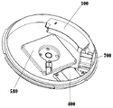
fig. 3 is a schematic structural diagram of another view angle of the ceiling lamp according to the embodiment of the present invention without the inductor and the storage battery;
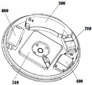
fig. 4 is a schematic structural diagram of an embodiment of the ceiling lamp including the storage battery according to the present invention;
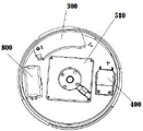
fig. 5 is a schematic structural diagram of an embodiment of the ceiling lamp including a storage battery and an inductor according to the present invention;
fig. 6 is a schematic structural diagram of an embodiment of the ceiling lamp including an inductor according to the present invention.
Detailed Description
In order to facilitate understanding of those skilled in the art, the present invention will be further described with reference to the following examples and drawings, which are not intended to limit the present invention. The present invention will be described in detail with reference to the accompanying drawings.
As shown in fig. 1-3, a portable ceiling lamp includes,
a base 100;
a heat dissipation substrate 200 fixedly disposed at a central position of the base 100;
a wire binding box 300 disposed at an edge of the base 100, having a line inlet 310 at one side and a line outlet 320 at the other side;
the wire connector 400 is arranged at the edge position of the base 100;
a light source assembly, comprising,
a light emitting element 510 attached and fixed to the upper end of the heat dissipating substrate 200,
a driving circuit assembly disposed in the wire harness box 300, wherein one end of a wire of the driving circuit assembly is connected to the light emitting assembly 510, and the other end of the wire of the driving circuit assembly is connected to an external power source through the wire connector 400;
the lamp cover 600 is sleeved on the edge of the base 100 and detachably connected with the base 100. Specifically, in implementation, a circle of the clamping grooves 110 is arranged at the base 100, and then the lower edge of the lamp cover 600 is clamped into the clamping grooves 110, but other modes can be implemented.
In this embodiment, through the design of the base 100, the wiring box 300 and the wire connector 400 are reasonably arranged at the base 100, so that the installation is convenient and simple, the wiring is quick, the whole lamp is simple in design, and the cost performance is high.
In a preferred embodiment of this embodiment, the heat dissipation substrate 200 is an aluminum member. Through adopting aluminium base board heat dissipation, can enough guarantee the radiating efficiency and also can practice thrift the cost, the sexual valence relative altitude.
As a preferred embodiment of this scheme, light emitting component 510 includes LED light source board 511 and light transmissive cover 512, LED light source board 511 laminating and fixed set up in the upper end of radiating substrate 200, light transmissive cover 512 dustcoat in LED light source board 511, the one corner of light transmissive cover 512 is provided with 513, 513 is used for bundling the wire.
In the embodiment, the wires are further bundled, so that the installation is more convenient, and the lamp is effectively safe and electric shock resistant to a certain extent.
As a preferred embodiment of the present disclosure, the lampshade 600 is obtained by polishing through a secondary optical sanding process. The light diffusion can be more reasonable.
As a preferred embodiment of this embodiment, the portable electronic device further includes an inductor 700, the inductor 700 is electrically connected to the driving circuit assembly, and the inductor 700 is fixedly disposed at an edge position of the base 100.
Referring to fig. 6, in the present embodiment, the sensor 700 is added to provide the lamp with the effect of sensing a lamp.
As the preferred embodiment of this scheme, still include battery 800, battery 800 with drive circuit subassembly electricity is connected, battery 800 is used for the ceiling lamp is electric power storage when normally working discharge and supply power when the ceiling lamp cuts off the power supply, battery 800 set up in the marginal position of base 100.
Referring to fig. 4, in the present embodiment, battery 800 is added to provide the effect of an emergency light to the lamp.
As a preferred embodiment of the present invention, the present invention further includes a sensor 700 and a storage battery 800, the sensor 700 is electrically connected to the driving circuit assembly, and the sensor 700 is fixedly disposed at an edge position of the base 100; battery 800 with the drive circuit subassembly electricity is connected, battery 800 is used for the ceiling lamp normal during operation electric power storage discharge when the ceiling lamp outage and supply power, battery 800 set up in the border position of base 100.
Referring to fig. 5, in the present embodiment, the sensor 700 and the battery 800 are added to provide the lamp with the effects of both the induction lamp and the emergency lamp.
The above description is only for the preferred embodiment of the present invention, and the present invention is not limited to the above description, and although the present invention is disclosed in the preferred embodiment, it is not limited to the above description, and any person skilled in the art can make some changes or modifications to equivalent embodiments without departing from the scope of the present invention, but all the technical solutions of the present invention are within the scope of the present invention.
Claims (7)
1. A portable ceiling lamp, which is characterized by comprising,
a base;
the heat dissipation substrate is fixedly arranged at the central position of the base;
the wire bundling box is arranged at the edge position of the base, one side of the wire bundling box is provided with a line inlet, and the other side of the wire bundling box is provided with a line outlet;
the wire connector is arranged at the edge position of the base;
a light source assembly, comprising a light source,
a light emitting component which is jointed and fixedly arranged at the upper end of the heat dissipation substrate,
the driving circuit assembly is arranged in the wire harness box, one end of a lead of the driving circuit assembly is connected with the light-emitting assembly, and the other end of the lead of the driving circuit assembly is connected with an external power supply through the wire connector;
the lamp shade is sleeved on the edge of the base and is detachably connected with the base.
2. The portable ceiling lamp of claim 1, wherein: the heat dissipation substrate is an aluminum component.
3. A portable ceiling lamp as claimed in claim 2, characterized in that: light emitting component includes LED light source board and printing opacity cover, LED light source board laminating and fixed set up in the upper end of heat dissipation base plate, printing opacity cover dustcoat in LED light source board, the one corner of printing opacity cover is provided with bunch structure, bunch structure is used for bundling the wire.
4. A portable ceiling lamp according to claim 3, characterized in that: the lampshade is obtained by polishing through a secondary optical polishing process.
5. A portable ceiling lamp according to claim 4, characterized in that: still include the inductor, the inductor with drive circuit subassembly electricity is connected, the inductor is fixed set up in the border position of base.
6. A portable ceiling lamp according to claim 4, characterized in that: still include the battery, the battery with the drive circuit subassembly electricity is connected, the battery is used for the ceiling lamp normal during operation electric power storage discharge when the ceiling lamp outage and supply power, the battery set up in the border position of base.
7. A portable ceiling lamp according to claim 4, characterized in that: the sensor is electrically connected with the driving circuit component and is fixedly arranged at the edge position of the base; the battery with the drive circuit subassembly electricity is connected, the battery is used for ceiling lamp normal during operation electric power storage discharge when the ceiling lamp cuts off the power supply, the battery set up in the border position of base.
Priority Applications (1)
| Application Number | Priority Date | Filing Date | Title |
|---|---|---|---|
| CN202221701948.6U CN217482638U (en) | 2022-07-04 | 2022-07-04 | Portable ceiling lamp |
Applications Claiming Priority (1)
| Application Number | Priority Date | Filing Date | Title |
|---|---|---|---|
| CN202221701948.6U CN217482638U (en) | 2022-07-04 | 2022-07-04 | Portable ceiling lamp |
Publications (1)
| Publication Number | Publication Date |
|---|---|
| CN217482638U true CN217482638U (en) | 2022-09-23 |
Family
ID=83316719
Family Applications (1)
| Application Number | Title | Priority Date | Filing Date |
|---|---|---|---|
| CN202221701948.6U Active CN217482638U (en) | 2022-07-04 | 2022-07-04 | Portable ceiling lamp |
Country Status (1)
| Country | Link |
|---|---|
| CN (1) | CN217482638U (en) |
-
2022
- 2022-07-04 CN CN202221701948.6U patent/CN217482638U/en active Active
Similar Documents
| Publication | Publication Date | Title |
|---|---|---|
| CN217482638U (en) | Portable ceiling lamp | |
| TWM315936U (en) | High-power LED lamp and LED device thereof | |
| CN216667295U (en) | LED lamp with high heat dissipation efficiency and convenient replacement | |
| CN201885105U (en) | Novel LED (light-emitting diode) ceiling down lamp | |
| CN212390187U (en) | Intelligent lamp | |
| CN210319555U (en) | Novel explosion-proof lamp | |
| CN210107196U (en) | Ceiling lamp convenient to install | |
| CN210179488U (en) | Outdoor emergency induction industrial and mining lamp | |
| CN209916764U (en) | LED lamp pearl sterilamp | |
| CN202501324U (en) | Light-emitting diode (LED) straight type industrial mining lamp | |
| CN201795351U (en) | LED ball lamp | |
| CN203273575U (en) | Led lamp | |
| CN212029218U (en) | Multi-functional court illumination lamps and lanterns | |
| WO2014089930A1 (en) | Led bulb lamp with non-isolated power supply | |
| CN104763895B (en) | AC LED lamp bead and lamp made of the same | |
| CN216169409U (en) | Cold source lamp | |
| CN217559719U (en) | Electric power storage type light sensing LED lamp | |
| CN210771913U (en) | Energy-saving low-power consumption vehicle-used lighting bulb | |
| CN212746035U (en) | LED module with high-efficient luminous efficiency | |
| CN213453240U (en) | Ceiling lamp | |
| CN215570229U (en) | Light source module of solar street lamp | |
| CN216952708U (en) | Light-gathering COB soft lamp strip | |
| CN202733511U (en) | Alternating current type multicore integrated light emitting diode (LED) metal halide lamp | |
| CN209213603U (en) | A kind of energy-saving LED lamp housing | |
| CN210662372U (en) | Prismatic LED point light source |
Legal Events
| Date | Code | Title | Description |
|---|---|---|---|
| GR01 | Patent grant | ||
| GR01 | Patent grant |