CN217453413U - Automatic shaping system for cylindrical materials - Google Patents
Automatic shaping system for cylindrical materials Download PDFInfo
- Publication number
- CN217453413U CN217453413U CN202221243688.2U CN202221243688U CN217453413U CN 217453413 U CN217453413 U CN 217453413U CN 202221243688 U CN202221243688 U CN 202221243688U CN 217453413 U CN217453413 U CN 217453413U
- Authority
- CN
- China
- Prior art keywords
- clamping
- module
- detection
- assembly
- polishing
- Prior art date
- Legal status (The legal status is an assumption and is not a legal conclusion. Google has not performed a legal analysis and makes no representation as to the accuracy of the status listed.)
- Active
Links
Images


Abstract
The utility model relates to an automation equipment field specifically discloses an automatic plastic system for cylindric material. The automatic shaping system comprises a rack, wherein a processing channel and a conveying assembly are arranged on the rack; the machine frame is also provided with an end face shaping module, a detection module and a sorting module, and the end face shaping module, the detection module and the sorting module are sequentially distributed along the conveying direction of the conveying assembly; the end face shaping module comprises two grinding units which are arranged oppositely left and right relative to the processing channel; wherein the detection module comprises a visual detection unit; the material sorting device is characterized by further comprising a control module, wherein the control module controls the sorting module to sort materials according to the detection result of the detection module. The automatic shaping system can finish the automatic shaping work of the cylindrical materials, has a detection function and reliably ensures the stability of the product quality.
Description
Technical Field
The utility model relates to an automation equipment field especially relates to an automatic plastic system for cylindric material.
Background
Common cylindrical materials comprise a metal cylinder, a plastic barrel, a paper cylinder and the like, and are usually processed into a long cylinder in processing, and then are cut into specific lengths according to requirements. However, since the cutting process is prone to form burrs or other defects at the end of the cylindrical material, a shaping process is required before use. The existing shaping processing mode is manual inspection and polishing, the working efficiency is low, and the product quality cannot be guaranteed.
Disclosure of Invention
The to-be-solved technical problem of the utility model is to provide an automatic shaping system for tube-shape material accomplishes the automatic plastic work of tube-shape material to possess the detection function, reliably guarantee product quality's stability.
In order to solve the technical problem, the utility model provides a technical scheme as follows: an automated reshaping system for a cylindrical material, comprising at least:
the device comprises a machine frame, a processing channel and a conveying assembly, wherein the conveying assembly is used for driving a cylindrical material to move along the processing channel in a single direction;
the machine frame is also provided with an end face shaping module, a detection module and a sorting module, and the end face shaping module, the detection module and the sorting module are sequentially distributed along the conveying direction of the conveying assembly;
the end face shaping module comprises two grinding units which are arranged oppositely left and right relative to the processing channel;
wherein, the detection module comprises a visual detection unit.
When processing, the conveying assembly drives the cylindrical material to move in the processing channel, the shaping processing is carried out on the end face shaping module in sequence, the processing quality detection is carried out on the detection module, and finally the product is sorted through the sorting module according to the detection structure. In the processing process, the control module acquires the detection structure in real time and adjusts the working states of the end face shaping module and the sorting module. The shaping system can finish the automatic shaping work of the cylindrical materials, has a detection function and reliably ensures the stability of the product quality.
Preferably, the conveying assembly comprises a first driving device and a plurality of brackets, and the first driving device drives the brackets to move along the processing channel. The bracket is used for placing the cylindrical materials and pushing the cylindrical materials to move synchronously along with the conveying assembly.
Preferably, the sharpening unit comprises a second driving device, a sharpening cutter head and a feeding mechanism, the feeding mechanism comprises a sharpening main shaft, and the second driving device drives the sharpening main shaft to rotate relative to the rack;
the coping spindle comprises a middle shaft and an outer sleeve, and the outer sleeve is rotatably and movably connected with the rack; the outer sleeve is sleeved on the intermediate shaft and limited to axially slide relative to the intermediate shaft and rotate synchronously in the circumferential direction; the feed mechanism also comprises a feed driving piece which drives the intermediate shaft to move axially relative to the outer sleeve;
the coping cutter head is arranged on the middle shaft.
When the end face shaping processing is carried out, the cylindrical material is arranged between the two grinding cutter heads, the second driving device drives the main shaft and the grinding cutter heads to rotate, the feeding driving piece drives the middle shaft and the grinding cutter heads to axially feed and move towards the direction of the cylindrical material, and the two grinding cutter heads simultaneously carry out grinding processing on two end faces of a product. And after the machining is finished, the driving part drives the intermediate shaft and the coping tool bit to reset so as to prepare for the next machining.
Preferably, the detection module comprises an end detection assembly; the end detection assembly comprises two first visual detection units which are arranged oppositely left and right relative to the processing channel. The end detection assembly is used for evaluating the end face grinding quality of the cylindrical product.
Preferably, the detection module further comprises a lateral detection assembly, the lateral detection assembly comprises a rotary clamping mechanism and a second visual detection unit, and the second visual detection unit is positioned above the processing channel;
the rotary clamping mechanism comprises two clamping heads which are arranged oppositely left and right relative to the processing channel;
the detection module further comprises a rotary driving mechanism, and the rotary driving mechanism drives at least one clamping head to rotate.
When detecting, two holding heads are relatively close to each other and carry out the centre gripping to cylindric material, and rotary drive mechanism drive holding head rotates to further drive cylindric material synchronous rotation. And in the rotating process of the cylindrical material, the second visual detection unit scans and detects the circumferential surface of the cylindrical material and evaluates the defects and the processing quality of the circumferential surface of the cylindrical material.
Preferably, the rotary driving mechanism comprises a third driving device and a transmission unit arranged between the clamping head and the third driving device, and the transmission unit adopts the matching transmission of a gear and a rack.
Preferably, the device also comprises an oiling component, wherein the oiling component is positioned in front of the end face shaping module in the conveying direction of the conveying component;
the oiling assembly comprises two oiling units, and the two oiling units are arranged oppositely left and right relative to the processing channel. The oil coating operation is carried out on the end face by the cylindrical material before the end face grinding, so that the end face grinding quality can be effectively improved.
Preferably, the polishing module is positioned between the end face shaping module and the detection module along the conveying direction of the conveying assembly;
the polishing module comprises two polishing units, and the two polishing units are oppositely arranged left and right relative to the processing channel; the polishing unit comprises a fourth driving device and a polishing piece, and the fourth driving device drives the polishing piece to work.
When the end face polishing machining is carried out, the cylindrical material is arranged between the two polishing pieces, the fourth driving device drives the polishing pieces to rotate, and the two polishing pieces polish two end faces of a product simultaneously.
Preferably, the sorting module further comprises a material placing assembly and a material taking assembly, wherein the material placing assembly is provided with a material placing station; the material taking assembly comprises a material clamping mechanism and a transferring mechanism, wherein the material clamping mechanism is used for clamping materials, and the transferring mechanism is used for driving the material clamping mechanism to move between a material taking station and a material placing station.
After the cylindrical materials are detected by the detection module, the cylindrical materials are conveyed to the material taking station by the conveying assembly, and the material taking assembly selectively takes out part of the cylindrical materials and places the part of the cylindrical materials into the material placing station according to detection results, so that the sorting operation of the cylindrical materials is realized.
Preferably, the clamping mechanism comprises a base, a clamping arm and a push rod, and the clamping arm and the push rod are connected with the base in a sliding mode in the same direction; one end of the clamping arm is provided with a material clamping unit,
the push rod is driven to slide relative to the base by the fifth driving device;
at least two position states are arranged between the clamping arm and the push rod:
in the first position state, the push rod and the clamping arm are positioned at a standby station, and the material clamping unit is in a loose state;
and in the process of entering the second position state from the first position state, the push rod pushes the clamping arm to enter the clamping station and drives the material clamping unit to enter the clamping state.
Drawings
FIG. 1 is a front view of an automated tubular material shaping system of the present embodiment;
FIG. 2 is a top view of the automated cylindrical material reshaping system of the present embodiment;
FIG. 3 is a top view of an end face shaping module of the automated shaping system for cylindrical materials according to the present embodiment;
FIG. 4 is a schematic structural diagram of an end surface shaping module in the automatic shaping system for cylindrical materials according to the embodiment;
FIG. 5 is an enlarged view of a portion of FIG. 4 at A;
FIG. 6 is a partial enlarged view of the portion B in FIG. 4;
fig. 7 is a schematic structural view illustrating the cooperation between the material clamping assembly and the sharpening head in the automatic shaping system for cylindrical materials according to the embodiment;
FIG. 8 is a top view of a polishing module in the automatic shaping system for cylindrical materials according to the embodiment;
FIG. 9 is a schematic diagram of a polishing module of the automated reshaping system for cylindrical materials according to the embodiment;
FIG. 10 is an enlarged view of a portion of FIG. 9 at C;
FIG. 11 is an enlarged view of a portion of FIG. 9 at D;
FIG. 12 is a schematic view of the material holding assembly and the polishing member of the present embodiment of the automated reshaping system for cylindrical material;
FIG. 13 is a top view of the end detection assembly of the automated tubular product reshaping system of this embodiment;
FIG. 14 is a front view of a lateral detection assembly of the present embodiment of the automated shaping system for tubular items;
FIG. 15 is a side view of the lateral detection assembly of the present embodiment of the automated tubular material reshaping system;
FIG. 16 is a schematic structural diagram of a rotary clamping mechanism in the automatic shaping system for cylindrical materials according to the embodiment;
FIG. 17 is an enlarged view of a portion of the soil 16 at E;
fig. 18 is a schematic structural diagram of a sorting module in the automatic shaping system for cylindrical materials according to the embodiment;
FIG. 19 is a schematic diagram of another state of the sorting module in the automated tubular material reshaping system according to the embodiment;
FIG. 20 is a schematic structural diagram of a transfer mechanism in the automatic shaping system for cylindrical materials according to the embodiment;
FIG. 21 is a schematic diagram illustrating the operation of the material clamping mechanism in the automatic shaping system for cylindrical materials according to the embodiment;
FIG. 22 is a front view of a material placement module of the present embodiment of the automated tubular material reshaping system;
fig. 23 is a working principle diagram of a secondary sorting mechanism in the automatic shaping system for cylindrical materials according to the embodiment.
Detailed Description
In order to make the objects, technical solutions and advantages of the present invention more clearly understood, the present invention is further described in detail below with reference to the accompanying drawings and embodiments. It should be understood that the specific embodiments described herein are merely illustrative of the invention and are not intended to limit the invention.
Examples
As shown in fig. 1 and 2, an automatic shaping system for cylindrical materials comprises a frame 1, wherein a processing channel 11 and a conveying assembly are arranged on the frame 1, and the conveying assembly is used for driving the cylindrical materials 9 to move along the processing channel 11 in a single direction. Specifically, the conveying assembly comprises a conveying chain and a first driving device, the conveying chain is distributed along the processing channel 11, and the first driving device drives the conveying chain to move along the processing channel 11 in a single direction. A plurality of brackets 13 are distributed on the conveying chain along the length direction, and the brackets 13 are used for placing the cylindrical materials 9 and pushing the cylindrical materials 9 to move synchronously along with the conveying assembly. The bracket 13 comprises two plates arranged in parallel, and V-shaped troughs are respectively arranged on the two plates.
As shown in fig. 1 and 2, the device further comprises an inlet assembly 2 and an outlet assembly 8, wherein the inlet assembly 2 is positioned at the inlet end of the processing channel 11, and the outlet assembly 8 is positioned at the outlet end of the processing channel 11. Specifically, the feeding assembly 2 is provided with a feeding channel, the discharging assembly 8 is provided with a discharging channel, and the feeding channel and the discharging channel are aligned with the processing channel 11. The cylindrical materials 9 to be processed sequentially enter the processing channel 11 from the feeding channel, and the qualified cylindrical materials 9 after processing are discharged from the discharging channel.
As shown in fig. 1 and 2, the processing channel 11 is provided with an oil coating station, a coping station 12, a polishing station 14, a detection station 16 and a material taking station 17 in sequence along a direction from a feeding end to a discharging end. The machine frame 1 is also provided with an oiling component 3, an end face shaping module 4, a polishing module 5, a detection module 6 and a sorting module 7, wherein the oiling component 3, the end face shaping module 4, the polishing module 5, the detection module 6 and the sorting module 7 are sequentially distributed along the conveying direction of the conveying component. The oiling component 3 corresponds to an oiling station, the end face shaping module 4 corresponds to a grinding station 12, the polishing module 5 corresponds to a polishing station 14, the detection module 6 corresponds to a detection station 16, and the sorting module 7 corresponds to a material taking station 17.
During processing, the conveying assembly drives the cylindrical material 9 to move in the processing channel 11, the shaping processing is sequentially carried out on the end face shaping module 4, the processing quality detection is carried out on the detection module 6, and finally the products are sorted through the sorting module 7 according to the detection structure.
As shown in fig. 1 and 2, the oiling assembly 3 includes an oil supply unit and two oiling units, the oiling units include oiling layers, and the oiling layers of the two oiling units are opposite to each other in the left-right direction with respect to the processing channel 11. The oiling layer can be a felt, and the oil supply unit can be an oil pump. The cylindrical material 9 is used for oiling the end face before end face grinding, so that the end face grinding quality can be effectively improved.
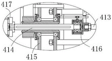
As shown in fig. 2 to 4, the end face shaping module 4 includes two sharpening units 41, each sharpening unit 41 includes a sharpening base 415, a sharpening head 414, a first feeding mechanism 413, and a second driving device 411, and the second driving device 411 is disposed on the sharpening base 415.
As shown in fig. 4-6, the first feeding mechanism 413 includes a sharpening spindle 414, the sharpening spindle 414 includes a middle shaft and an outer sleeve, and the outer sleeve is rotatably and movably connected with the sharpening base 415. The outer sleeve is sleeved on the intermediate shaft and limited to axially slide relative to the intermediate shaft and circumferentially rotate synchronously. Specifically, the intermediate shaft is in key connection with the outer sleeve.
As shown in fig. 4, the second driving device 411 drives the sharpening spindle 414 to rotate relative to the sharpening base 415, specifically, the second driving device 411 is a motor, and the second driving device 411 and the outer sleeve are in belt transmission or gear transmission.
As shown in fig. 3 and 4, the thinning tool 414 is disposed on the intermediate shaft, the thinning tool 414 of the two thinning units 41 are opposed to each other in the left-right direction, a machining section is formed between the two thinning units 41, and the thinning station 12 corresponds to the machining section.
As shown in fig. 4-6, the first feed mechanism 413 further includes a feed drive driving the intermediate shaft to move axially relative to the outer sleeve, the feed drive being defined to be slidably connected to the sharpening base 415 in an axial direction along the sharpening spindle 414.
As shown in fig. 4-6, in particular, the feed drive member comprises an electric, pneumatic or hydraulic cylinder. A first coupling member 416 is provided between the feed drive member and the intermediate shaft, said first coupling member 416 being defined to be rotationally movably linked with the intermediate shaft and being fixedly connected to the output end of the feed drive member in the circumferential direction. Specifically, the intermediate shaft is connected to the first coupling member 416 by a thrust bearing.
As shown in fig. 4-6, a spindle compensation mechanism 412 is further included, and the spindle compensation mechanism 412 includes a compensation driving unit for driving the feed driving member to slide relative to the thinning base 415. The compensation driving unit comprises a driving part and a transmission mechanism, specifically, the driving part of one sharpening unit 41 is a manual rotating wheel, and the driving part of the other sharpening unit 41 is a stepping motor. The transmission mechanism comprises a screw rod and a nut, the screw rod is fixedly connected with the feeding driving piece, the nut is movably arranged on the grinding base 415 in a rotating mode, and the driving piece drives the nut to rotate through the gear transmission mechanism.
During end face shaping, the cylindrical material 9 moves to the grinding station 12 and is located between the two grinding cutter heads 414, the second driving device 411 drives the grinding main shaft 414 and the grinding cutter heads 414 to rotate, the feeding driving piece drives the middle shaft and the grinding cutter heads 414 to axially feed and move towards the cylindrical material 9, and the two grinding cutter heads 414 simultaneously grind two end faces of the cylindrical material 9. And after the machining is finished, the driving part drives the middle shaft and the coping tool bit 414 to reset. The compensation driving unit is used for adjusting the position of the first feeding mechanism 413 relative to the grinding base 415 so as to adapt to the cylindrical materials 9 with different length specifications.
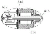
As shown in fig. 1, fig. 2, fig. 8 and fig. 9, the polishing module 5 includes two polishing units 51, the polishing units 51 are disposed on the frame 1, and the polishing units 51 include a polishing base 515, a polishing member 516, a second feeding mechanism 513 and a fourth driving device 511. Specifically, the polishing base 515 of at least one of the polishing units 51 is slidably connected to the frame 1 in the axial direction along the polishing spindle 514.
As shown in fig. 9-11, the second feeding mechanism 513 includes a polishing spindle 514, and the polishing spindle 514 includes a middle shaft and an outer sleeve, and the outer sleeve is rotatably connected to the polishing base 515. The outer sleeve is sleeved on the intermediate shaft and limited to axially slide relative to the intermediate shaft and circumferentially rotate synchronously. Specifically, the intermediate shaft is in key connection with the outer sleeve.
As shown in fig. 9, the fourth driving device 511 is provided on the polishing platen 515, and drives the polishing spindle 514 to rotate relative to the polishing platen 515. Specifically, the fourth driving device 511 is a motor, and the fourth driving device 511 and the outer sleeve are in belt transmission or gear transmission.
As shown in fig. 9 to 11, the polishing members 516 are disposed on the middle shaft, and the polishing members 516 of the two polishing units 51 are opposed to each other left and right. A processing interval is formed between the two polishing units 51, and the polishing station 14 corresponds to the processing interval. Specifically, the polishing member 516 is sandpaper.
As shown in fig. 9-11, the second feed mechanism 513 further includes a feed drive that drives the intermediate shaft to move axially relative to the outer sleeve. Specifically, the feeding driving piece is an electric cylinder, an air cylinder or a hydraulic cylinder. A second coupling member 512 is arranged between the feed driving member and the intermediate shaft, and the second coupling member 512 is defined to be in a rotary movable link with the intermediate shaft and is fixedly connected with the output end of the feed driving member in the circumferential direction. Specifically, the intermediate shaft is connected to the second coupling member 512 by a thrust bearing.
As shown in fig. 9-11, in particular, the frame 1 is further provided with an adjusting assembly 52 for driving the polishing base 515 to slide relative to the frame 1. The adjustment assembly 52 includes an adjustment driver 521 and a lead screw transmission 522. Specifically, a nut is arranged on the polishing base 515, the screw rod is rotatably and movably connected with the frame 1, and the adjusting driving member 521 is a stepping motor and drives the screw rod to rotate.
As a specific embodiment, the polishing bases 515 of the two polishing units 51 are both slidably connected to the frame 1, and the adjusting assemblies 52 of the two polishing units 51 are linked, that is, the two lead screws connected to the polishing bases 515 are the same, or the two lead screws are connected through a coupler, and the rotation directions of the nuts on the two polishing units 51 are opposite.
When the end face polishing processing is carried out, the cylindrical material 9 moves to the polishing station 14 and is positioned between the two polishing pieces 516, the fourth driving device 511 drives the polishing main shaft 514 and the polishing pieces 516 to rotate, the feeding driving piece drives the middle shaft and the polishing pieces 516 to axially feed and move towards the direction of the cylindrical material 9, and the two polishing pieces 516 simultaneously polish two end faces of a product. And after the machining is finished, the driving part driving intermediate shaft and the polishing part 516 are reset. The adjustment drive 521 is used to adjust the position of the polishing unit 51 relative to the frame 1 to accommodate cylindrical materials 9 of different length specifications.
Further, as shown in fig. 4, fig. 7, fig. 9 and fig. 12, the material clamping assembly 42 is further included, the material clamping assembly 42 includes a lifting member 422, a positioning member 421 and a jacking driving member 423, the positioning member 421 is located above the lifting member 422, and a clamping space is formed between the lifting member 422 and the positioning member 421. The lifting driving member 423 drives the lifting member 422 to move up and down relative to the positioning member 421. The jacking driving piece 423 is an air cylinder, an electric cylinder or a hydraulic cylinder.
As shown in fig. 4, 7, 9 and 12, the end face shaping module 4 and the polishing module 5 each include a material holding assembly 42 for lifting the cylindrical material 9 off the bracket 13, and in particular, the lifting member 422 passes between the two plates of the bracket 13.
As shown in fig. 7, the following describes a specific working manner by taking the material holding assembly 42 in the end face shaping module 4 as an example: the cylindrical material 9 moves to the coping station 12 on the bracket 13, the jacking driving piece 423 drives the lifting piece 422 to ascend and pushes the cylindrical material 9 to move to the positioning piece 421, and the lifting piece 422 and the positioning piece 421 pre-clamp the cylindrical material 9. After the machining is finished, the lifting piece 422 resets, and the machined product resets to the bracket 13, so that the single machining is finished.
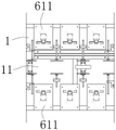
As shown in fig. 1 and 2, the inspection module 6 includes an end inspection assembly 61 and a side inspection assembly 62, and the end inspection assembly 61 and the side inspection assembly 62 are distributed along the processing passage 11.
As shown in fig. 13, in particular, the end detection assembly 61 includes two first visual detection units 611 disposed opposite to each other in the left-right direction with respect to the processing passage 11. The end detection assembly 61 is used for evaluating the end face grinding quality of the cylindrical product.
Specifically, as shown in fig. 14 and 15, the lateral detection assembly 62 includes a rotary clamping mechanism and a second visual detection unit 621, and the second visual detection unit 621 is located above the rotary clamping mechanism. Specifically, the rack 1 is provided with a mounting bracket 15, and the second visual detection unit 621 is disposed on the mounting bracket 15. The second visual inspection unit 621 includes a camera and an illumination device.
As shown in fig. 14 and 15, the second visual detection unit 621 is defined to be adjustable in relative position to the mounting bracket 15 in the horizontal direction and the vertical direction. The horizontal and vertical positions of the second visual inspection unit 621 may be appropriately adjusted according to the specification of the product. Specifically, the mounting bracket 15 includes a guide rod 152, a connecting cross rod 154 and a connecting vertical rod 156, the guide rod 152 is arranged along the vertical direction, the connecting cross rod 154 is connected with the guide rod 152 in a sliding manner, the connecting vertical rod 156 is connected with the connecting cross rod 154 in a sliding manner along the horizontal direction, and locking devices are respectively arranged between the connecting cross rod 154 and the guide rod 152, and between the connecting cross rod 154 and the connecting vertical rod 156, so as to lock the second visual detection unit 621 at a specific position.
As shown in fig. 14 and 15, the second visual detection unit 621 is disposed at a lower end of the connecting vertical rod 156, and an angle adjustment mechanism is disposed between the second visual detection unit 621 and the connecting vertical rod 156.
As shown in fig. 14 and 15, the mounting bracket 15 is further provided with a protective cover 155, and the frame 1 is further provided with a vertical adjustment mechanism 153 for driving the protective cover 155 to move in the vertical direction. The protective cover 155 can protect the second visual detection unit 621, and the vertical adjustment mechanism 153 can adjust the relative position between the second visual detection unit 621 and the protective cover 155, so as to facilitate the operation of the second visual detection unit 621. Specifically, the mounting bracket 15 further includes a top platform 151, the vertical adjusting mechanism 153 is disposed on the top platform 151, and the vertical adjusting mechanism 153 includes an air cylinder, an electric cylinder or a hydraulic cylinder.
As shown in fig. 14, 16 and 17, the rotary clamping mechanism includes two clamping units 622, the clamping units 622 include a clamping base 6222 and clamping heads 6223, the clamping heads 6223 of the two clamping units 622 are arranged opposite to each other, and the rotary clamping mechanism further includes a telescopic driving member 6221 for driving the two clamping heads 6223 to move relatively closer to or away from each other.
As shown in fig. 14, 16 and 17, in particular, one of the clamping units 622 is a fixed unit 6226, and the other clamping unit 622 is a movable unit 6225. The gripping head 6223 of said fixing unit 6226 is defined so as to be arranged rotatably, in a circumferential direction, with the corresponding gripping base 6222, and so as to be arranged fixedly in an axial direction. The gripping head 6223 of said movable unit 6225 is defined to be rotatably movable circumferentially with respect to the gripping base 6222, telescopically arranged axially.
As shown in fig. 14, 16 and 17, the telescopic driving member 6221 is an electric cylinder, an air cylinder or a hydraulic cylinder, the telescopic driving member 6221 is disposed on the clamping base 6222 of the movable unit 6225, and the corresponding clamping head 6223 is connected to the telescopic end of the telescopic driving member 6221.
During detection, the cylindrical material 9 is firstly placed between the two clamping heads 6223, then the clamping heads 6223 of the movable unit 6225 extend out, the cylindrical material 9 is pushed until the two clamping heads 6223 simultaneously push the cylindrical material 9 tightly, and reliable clamping of the cylindrical material 9 is realized.
As shown in fig. 14, 16 and 17, further, the gripping end of the gripping head 6223 is provided with a guide ramp. The guiding bevel can guide the end of the clamping head 6223 to be inserted into the cylindrical material 9 in the process that the clamping head 6223 tightly pushes the cylindrical material 9, and can play a role in forcibly centering the cylindrical material 9, so that the axis of the cylindrical material 9 is ensured to be basically coincident with the rotation center of the clamping head 6223.
As shown in fig. 14, 16 and 17, a demoulding unit 6224 is further provided on the movable unit 6225, and a demoulding stopper is provided on the demoulding unit 6224. In order to realize automatic discharging, the cylindrical product needs to realize automatic demoulding operation after the detection is finished. Thus, in the clamped state, the cartridge material 9 is arranged to have a clamping force with the clamping head 6223 on the movable unit 6225 that is slightly larger than the clamping force of the clamping head 6223 on the stationary unit 6226. After the detection is finished, the cylindrical material 9 retreats along with the clamping head 6223 of the movable unit 6225 and is separated from the clamping head 6223 under the blocking action of the demolding stop block in the retreating process, so that demolding is realized.
Specifically, drawing of patterns dog set up the circularity, the supporting head 6223 that corresponds passes in the drawing of patterns dog, through the cooperation clearance between reasonable setting drawing of patterns dog and the supporting head 6223, can guarantee the drawing of patterns effect to different products.
As shown in fig. 14, 16 and 17, the clamping device further comprises a rotary driving mechanism 623, wherein the rotary driving mechanism 623 drives at least one clamping head 6223 to rotate; the rotary driving mechanism 623 comprises a third driving device (not shown in the figure and provided as a rotary motor) and a transmission assembly, the transmission assembly comprises a driving wheel (not shown in the figure), a driven wheel 6231 and a transmission rack 6232, and the third driving device drives the driving wheel to rotate. The driven wheel 6231 and the corresponding clamping head 6223 are coaxially arranged and limited to synchronously rotate; the transmission rack 6232 is slidably disposed on the frame 1 and engaged with the driving gear and the driven gear respectively. In particular, the driven wheel 6231 is provided on the fixing unit 6226.
When detecting, two clamping head 6223 carry out the centre gripping to cylindric material 9, and rotary drive mechanism 623 drive clamping head 6223 rotates to further drive cylindric material 9 synchronous revolution. During the rotation, the second visual inspection unit 621 performs scanning inspection on the circumferential surface of the cylindrical material 9.
As shown in fig. 16 and 17, the cutting device further comprises a cutter unit 6233, wherein the cutter unit 6233 is arranged on the transmission rack 6232, and the cutting edge is arranged towards the corresponding clamping head 6223. In the process of detecting the rotation of the cylindrical material 9, the cutter unit 6233 synchronously performs groove cutting operation on the circumferential surface of the cylindrical material 9, and is particularly suitable for paper tube products.
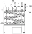
As shown in fig. 1, fig. 2 and fig. 18, the sorting module 7 includes a material taking assembly 71 and a material placing assembly 72, the material placing assembly 72 includes a material placing support 721, the material taking assembly 71 is located on one side of the material placing support 721, and the material placing support 721 is provided with a material placing station 73.
As shown in fig. 18 and 19, the material taking assembly 71 includes a material gripping mechanism 712 and a transfer mechanism 711, the material gripping mechanism 712 is used for gripping the material, and the transfer mechanism 711 is used for driving the material gripping mechanism 712 to move between the material taking station 17 and the material placing station 73.
Specifically, as shown in fig. 20, the transfer mechanism 711 includes a supporting frame 7113, and the supporting frame 7113 is located at one side of the material placing support 721. The supporting frame 7113 is provided with a mounting beam 7112 and a turning power unit 7111 for driving the mounting beam 7112 to rotate around the length direction. The mounting beam 7112 is provided with a rotating arm 7114, and the rotating arm 7114 and the mounting beam 7112 are perpendicular to each other and rotate synchronously along with the mounting beam 7112. The material clamping mechanism 712 is arranged on the rotating arm 7114. The overturning power unit 7111 is a rotating motor. Through the rotation of the mounting beam 7112, the rotating arm 7114, the material clamping mechanism 712 and the cylindrical material 9 are turned over up and down, so that the cylindrical material 9 is transferred between the material taking station 17 and the material placing station 73.
The length of the rotating arm 7114 is adjustable. Specifically, the rotating arm 7114 includes a telescopic adjusting structure, which includes an air cylinder or an electric cylinder. In the process of overturning the material clamping mechanism 712, the movement areas of the rotating arm 7114 and the material clamping mechanism 712 can be adjusted by changing the length of the rotating arm 7114, so that the possibility of interference between the rotating arm 7114 and the material clamping mechanism 712 and supporting equipment is reduced on the premise of ensuring the in-place transfer.
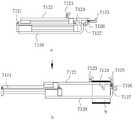
Specifically, as shown in fig. 21, the clamping mechanism 712 includes a base 7121 and clamping arms 7122, wherein the base 7121 is connected to the rotating arm 7114, and the clamping arms 7122 are slidably connected to the base 7121. One end of the clamping arm 7122 is provided with a clamping unit, and the clamping arm 7122 has at least two position states relative to the base 7121: in the first position, the clamping arm 7122 is located at a standby station, and the clamping unit is in a released state; when the clamping arms 7122 are in the process of entering the second position state from the first position state, the clamping arms 7121 slide and extend relative to the base portion 7121 to enter a clamping station; after the clamping arm 7122 enters the clamping station, the clamping unit enters a clamping state.
As shown in fig. 21, the clamping unit 622 includes a fixed clamping block 7123 and a movable clamping block 7125, wherein the fixed clamping block 7123 is fixedly disposed at an upper side of the clamping arm 7122, the movable clamping block 7125 is rotatably and movably connected to an end of the clamping arm 7122, and an elastic member is disposed between the movable clamping block 7125 and the clamping arm 7122.
As shown in fig. 21, a fifth driving device is further included, which includes a push rod 7128 and a power unit (not shown), wherein the push rod 7128 is slidably connected to the base 7121, and the sliding direction of the push rod 7128 relative to the base 7121 is the same as the sliding direction of the clamping arms 7122. The push rod 7128 is positioned below the clamping arms 7122, and the power unit drives the push rod 7128 to slide relative to the base 7121. And a fixed stop block 7124 is arranged on the lower side of the clamping arm 7122. The clamp also comprises a movable stop 7126, wherein the movable stop 7126 and the movable clamping block 7125 are integrally arranged and synchronously rotate relative to the clamping arm 7122. An operation space is formed between the movable clamping block and the fixed clamping block. The push rod 7128 is provided with a shifting block 7127, and the shifting block 7127 extends into the operation space. The power unit is a cylinder.
In the material taking operation, the material clamping mechanism is first in a state shown in a part a in fig. 21. The fifth driving device drives the push rod 7128 to slide and extend, the shifting block 7127 on the push rod 7128 contacts with the movable stop 7126, and the clamping arm 7122 moves along with the push rod 7128 due to the fact that the elastic piece is arranged between the movable clamping block 7125 and the clamping arm 7122. Since the moving stroke of the push rod 7128 relative to the base 7121 is greater than that of the clamping arm 7122 relative to the base 7121, after the clamping unit 622 enters the material taking station 17, the clamping arm 7122 extends into the through hole of the cylindrical material 9, the clamping arm 7122 stops sliding at first, the push rod 7128 continues to move and drives the movable clamping block 7125 to rotate against the elastic force of the elastic member, that is, the state shown in part b in fig. 21 is achieved. The movable clamping block 7125 rotates to a clamping state and is matched with the fixed clamping block 7123 to limit the cylindrical material 9, so that the cylindrical material 9 is clamped.
After the clamping mechanism 712 clamps the cylindrical material 9, the turning power unit 7111 operates, the rotating arm 7114 and the clamping mechanism 712 turn over, and the cylindrical material 9 is transferred to the material placing station 73, i.e., the state shown in fig. 19. During the turning process, the clamping arms 7122 are always in the second position state relative to the base 7121. After the material placing station 73 is reached, the fifth driving device works to drive the push rod 7128 to reset, and in the process of resetting the push rod 7128, the shifting block 7127 is in contact with the fixed stop block 7124 to push the clamping arm 7122 to reset.
The tubular goods 9 are fed into the material-taking station 17 with the conveyor assembly after being detected by the detection module 6. Wherein the material taking assembly 71 is positioned between the material placing support 721 and the feeding station. The material taking assembly 71 selectively takes out part of the cylindrical materials 9 into the material placing station 73 according to the detection result, so as to realize the sorting operation of the cylindrical materials 9. The take-off assembly 71 may be arranged to take off only defective products, which are delivered out of the take-off station 17 with the movement of the conveyor assembly.
Further, as shown in fig. 22 and 23, the material placing support 721 is further provided with a secondary sorting mechanism, and correspondingly, the secondary sorting mechanism further includes at least two receiving units 74, and the secondary sorting mechanism selectively feeds the cylindrical materials 9 on the material placing station 73 into each receiving unit 74. Note that, since the two storage units are different in structure and installation position, reference numerals 74 are used in both fig. 18 and fig. 19, and it should be noted that the same reference numerals do not correspond to different features.
The transfer mechanism 711 performs primary sorting on the cylindrical materials 9, and the secondary sorting mechanism performs secondary sorting on the cylindrical materials 9 entering the material placing station 73. And in a secondary sorting mode, the classification quantity of the sorted products is increased, so that the product processing is more refined.
Specifically, as shown in fig. 22 and 23, one of the receiving units 74 is a waste unit, the other receiving unit 74 is a unit to be processed, and a feeding port of the receiving unit 74 is disposed at a side of the material placing station 73. The secondary sorting mechanism comprises a pushing unit 751, and the pushing unit 751 is used for pushing the cylindrical materials 9 from the material placing station 73 to the feeding hole of the containing unit 74. The pushing unit 751 includes a cylinder.
As shown in fig. 22, the unit to be processed is a storage channel extending in an "S" shape on the material placing support 721, and a feeding port of the storage channel is located at the upper end of a discharging port. The storage channel extending in the shape of an S can make full use of the remaining space of the material placing supports 721 to increase the storage quantity. The feed inlet is positioned above the discharge outlet, and the cylindrical material 9 moves towards the discharge outlet under the action of gravity after entering the feed inlet.
As shown in fig. 22 and 23, the secondary sorting mechanism further includes a rotating rod 7522 and a rotating driving member 7521, one end of the rotating rod 7522 is rotatably and movably connected to the material placing support 721, and the rotating driving member 7521 drives the rotating rod 7522 to rotate relative to the material placing support 721. The feed opening of one of the receiving units 74 corresponds to the connecting end of the rotary rod member 7522. The material placing station 73 is provided with a material placing support 731, and the material placing support 731 is provided with a containing groove corresponding to the rotary rod member 7522. The rotary drive 7521 includes a cylinder.
After the cylindrical material 9 is placed in the material placing station 73, that is, in a state shown in a part c in fig. 23, the cylindrical material 9 can be selectively pushed to the corresponding containing unit 74 according to the detection result, and also by rotating the rotating rod 7522, the cylindrical material 9 can be rolled down into the corresponding containing unit 74 under the action of gravity, that is, in a state shown in a part d in fig. 23. The pushing unit 751 and the rotating bar 7522 can be arranged for the discharge of two different categories of products.
Specifically, as shown in fig. 23, the material placing support 731 includes at least two sets of material placing members arranged in parallel, and a containing groove is formed between the two material placing members. Each group of the material placing pieces comprises two upright posts which are vertically arranged.
The material sorting device further comprises a control module, and the control module controls the sorting module 7 to sort materials according to the detection result of the detection module 6. In the machining process, the control module acquires the detection structure in real time, adjusts the working states of the end face shaping module 4, the polishing module 5 and the sorting module 7, and can adjust the distance between the two grinding tool bits 414 in real time by controlling the working state of the spindle compensation mechanism 412 so as to achieve the optimal shaping effect. The shaping system can finish the automatic shaping work of the cylindrical materials, has a detection function and reliably ensures the stability of the product quality.
In summary, the above description is only a preferred embodiment of the present invention and should not be taken as limiting the invention, and any modifications, equivalents and improvements made within the spirit and principles of the present invention should be included within the scope of the present invention.
Claims (10)
1. Automated reshaping system for cylindrical objects, characterized in that it comprises at least:
the device comprises a machine frame, a processing channel and a conveying assembly, wherein the conveying assembly is used for driving a cylindrical material to move along the processing channel in a single direction;
the machine frame is also provided with an end face shaping module, a detection module and a sorting module, and the end face shaping module, the detection module and the sorting module are sequentially distributed along the conveying direction of the conveying assembly;
the end face shaping module comprises two grinding units which are arranged oppositely left and right relative to the processing channel;
wherein, the detection module comprises a visual detection unit.
2. The automated reshaping system of claim 1, wherein: the conveying assembly comprises a first driving device and a plurality of brackets, and the first driving device drives the brackets to move along the processing channel.
3. The automated shaping system of claim 1, wherein: the grinding unit comprises a second driving device, a grinding tool bit and a feeding mechanism, the feeding mechanism comprises a grinding main shaft, and the second driving device drives the grinding main shaft to rotate relative to the rack;
the coping spindle comprises a middle shaft and an outer sleeve, and the outer sleeve is rotatably and movably connected with the rack; the outer sleeve is sleeved on the intermediate shaft and limited to axially slide relative to the intermediate shaft and rotate synchronously in the circumferential direction; the feed mechanism also comprises a feed driving piece which drives the intermediate shaft to move axially relative to the outer sleeve;
the coping cutter head is arranged on the middle shaft.
4. The automated reshaping system of claim 1, wherein: the detection module comprises an end detection assembly; the end detection assembly comprises two first visual detection units which are opposite to each other at the left and the right relative to the processing channel.
5. The automated reshaping system of claim 4, wherein: the detection module further comprises a lateral detection assembly, the lateral detection assembly comprises a rotary clamping mechanism and a second visual detection unit, and the second visual detection unit is positioned above the processing channel;
the rotary clamping mechanism comprises two clamping heads which are oppositely arranged left and right relative to the processing channel;
the detection module further comprises a rotary driving mechanism, and the rotary driving mechanism drives at least one clamping head to rotate.
6. The automated reshaping system of claim 5, wherein: the rotary driving mechanism comprises a third driving device and a transmission unit arranged between the clamping head and the third driving device, and the transmission unit adopts the matching transmission of a gear and a rack.
7. The automated reshaping system of claim 1, wherein: the oil coating assembly is positioned in front of the end face shaping module in the conveying direction of the conveying assembly;
the oiling assembly comprises two oiling units, and the two oiling units are arranged oppositely left and right relative to the processing channel.
8. The automated reshaping system of claim 1, wherein: the polishing module is positioned between the end face shaping module and the detection module in the conveying direction of the conveying assembly;
the polishing module comprises two polishing units, and the two polishing units are oppositely arranged left and right relative to the processing channel; the polishing unit comprises a fourth driving device and a polishing piece, and the fourth driving device drives the polishing piece to work.
9. The automated shaping system according to any one of claims 1-8, wherein: the sorting module also comprises a material placing component and a material taking component, and the material placing component is provided with a material placing station; the material taking assembly comprises a material clamping mechanism and a transferring mechanism, wherein the material clamping mechanism is used for clamping materials, and the transferring mechanism is used for driving the material clamping mechanism to move between a material taking station and a material placing station.
10. The automated reshaping system of claim 9, wherein: the clamping mechanism comprises a base, a clamping arm and a push rod, and the clamping arm and the push rod are in sliding connection with the base in the same direction; one end of the clamping arm is provided with a material clamping unit,
the device also comprises a fifth driving device, wherein the fifth driving device drives the push rod to slide relative to the base;
at least two position states are arranged between the clamping arm and the push rod:
in the first position state, the push rod and the clamping arm are positioned at a standby station, and the material clamping unit is in a loose state;
and in the process of entering the second position state from the first position state, the push rod pushes the clamping arm to enter the clamping station and drives the material clamping unit to enter the clamping state.
Priority Applications (1)
| Application Number | Priority Date | Filing Date | Title |
|---|---|---|---|
| CN202221243688.2U CN217453413U (en) | 2022-05-23 | 2022-05-23 | Automatic shaping system for cylindrical materials |
Applications Claiming Priority (1)
| Application Number | Priority Date | Filing Date | Title |
|---|---|---|---|
| CN202221243688.2U CN217453413U (en) | 2022-05-23 | 2022-05-23 | Automatic shaping system for cylindrical materials |
Publications (1)
| Publication Number | Publication Date |
|---|---|
| CN217453413U true CN217453413U (en) | 2022-09-20 |
Family
ID=83277478
Family Applications (1)
| Application Number | Title | Priority Date | Filing Date |
|---|---|---|---|
| CN202221243688.2U Active CN217453413U (en) | 2022-05-23 | 2022-05-23 | Automatic shaping system for cylindrical materials |
Country Status (1)
| Country | Link |
|---|---|
| CN (1) | CN217453413U (en) |
Cited By (1)
| Publication number | Priority date | Publication date | Assignee | Title |
|---|---|---|---|---|
| CN115805486A (en) * | 2022-12-23 | 2023-03-17 | 太仓市天丝利塑化有限公司 | Highlight traceless trimming device of automobile active air inlet grille |
-
2022
- 2022-05-23 CN CN202221243688.2U patent/CN217453413U/en active Active
Cited By (2)
| Publication number | Priority date | Publication date | Assignee | Title |
|---|---|---|---|---|
| CN115805486A (en) * | 2022-12-23 | 2023-03-17 | 太仓市天丝利塑化有限公司 | Highlight traceless trimming device of automobile active air inlet grille |
| CN115805486B (en) * | 2022-12-23 | 2024-01-23 | 太仓市天丝利塑化有限公司 | Highlight traceless trimming device for automobile active air inlet grille |
Similar Documents
| Publication | Publication Date | Title |
|---|---|---|
| CN111496585A (en) | Automatic bar grinding machine | |
| CN110480033B (en) | Neodymium iron boron cutting machine tool | |
| CN217453413U (en) | Automatic shaping system for cylindrical materials | |
| CN113352128A (en) | Arc triangle workpiece machining device capable of detecting inner diameter of workpiece central column | |
| CN111152024A (en) | Shaft part drilling and tapping integrated processing equipment | |
| CN110773768A (en) | Radial drilling machine | |
| US5465471A (en) | Apparatus for machining bars | |
| CN111546147A (en) | Crystal glass rod grinding machine and limiting device thereof | |
| CN111347063B (en) | Automatic double-spindle lathe with feeding and turning functions | |
| CN219726824U (en) | Integrated grinding machine | |
| CN210335112U (en) | Equipment for machining spring chuck | |
| CN114986296A (en) | Automatic shaping system for cylindrical materials | |
| CN214419217U (en) | Automatic chamfering machine for ceramic ferrule | |
| CN210413950U (en) | Special numerical control automatic grinding machine for spherical surface of spherical roller | |
| CN111975478A (en) | Be used for automatic unloading and automatic grinding equipment of interior external surface of going up of bearing inner race | |
| CN112276589A (en) | Intelligent processing assembly line for large-diameter bearing bush | |
| CN112276588A (en) | Intelligent machining process for large-diameter bearing bush | |
| CN111014766A (en) | Motor shaft hole processing equipment | |
| KR20050015773A (en) | Transfer machine for Piston of Vehicle brake | |
| CN220372811U (en) | Peripheral chamfer grinder for milling cutter blade | |
| CN114669783B (en) | Inclined plane machining equipment and method for lipstick middle bundle tube | |
| CN220295855U (en) | Material moving device for numerical control lathe with feeding tailstock | |
| CN217858865U (en) | Bolt drilling equipment | |
| CN216359319U (en) | Numerical control drilling machine convenient to continuous processing | |
| CN219444725U (en) | Electrode cap quick feeding device and electrode cap processing machine tool |
Legal Events
| Date | Code | Title | Description |
|---|---|---|---|
| GR01 | Patent grant | ||
| GR01 | Patent grant |