CN217432896U - Cutting equipment is used in power cord processing production - Google Patents
Cutting equipment is used in power cord processing production Download PDFInfo
- Publication number
- CN217432896U CN217432896U CN202221025540.1U CN202221025540U CN217432896U CN 217432896 U CN217432896 U CN 217432896U CN 202221025540 U CN202221025540 U CN 202221025540U CN 217432896 U CN217432896 U CN 217432896U
- Authority
- CN
- China
- Prior art keywords
- power cord
- rod
- cutting
- threaded rod
- cutting equipment
- Prior art date
- Legal status (The legal status is an assumption and is not a legal conclusion. Google has not performed a legal analysis and makes no representation as to the accuracy of the status listed.)
- Active
Links
Images


Landscapes
- Details Of Cutting Devices (AREA)
Abstract
The utility model discloses a cutting equipment is used in power cord processing production, including the equipment body, the equipment body includes: the clamping device is arranged above the left side of the base, a fixed shaft is arranged in front of the side face of the clamping device, a rotating rod is arranged above the fixed shaft, and the rotating rod penetrates through the fixed shaft and is movably connected with the fixed shaft; the utility model discloses a set up stop device, can prevent that the power cord from squinting, through setting up the rotary rod, can outwards rotate the rotary rod and conveniently put the power cord on, through setting up the conveyer belt, can make the power cord that is cut away removed, prevent that the power cord from piling up, improved the work efficiency of device.
Description
Technical Field
The utility model relates to a power cord processing technology field specifically is a cutting equipment is used in power cord processing production.
Background
The power line is a wire that transmits current. The common way of current transfer is point-to-point transfer. The power cord can be divided into an AC power cord and a DC power cord according to the purpose, generally, the AC power cord is a wire passing through AC with higher voltage, and the DC cord basically passes through DC with lower voltage, and in the process of processing the power cord, the power cord is often required to be cut to a fixed length, so a power cord processing, producing and cutting device is required.
Present power cord processing production cutting equipment has some problems still, and the material loading is convenient inadequately in traditional course of working, can reduce work efficiency, and the electric wire after the cutting can't in time be cleared up and can pile up on table surface, influences subsequent cutting, and the practicality of device is relatively poor.
SUMMERY OF THE UTILITY MODEL
An object of the utility model is to provide a cutting equipment is used in power cord processing production to solve the problem that proposes among the above-mentioned background art.
In order to achieve the above purpose, the utility model provides the following technical scheme: the utility model provides a power cord processing production is with cutting equipment, includes the equipment body, the equipment body includes:
the device comprises a base, four supporting legs and rollers, wherein the four supporting legs are arranged below the base;
the clamping device is arranged above the left side of the base, a fixed shaft is arranged in front of the side face of the clamping device, a rotating rod is arranged above the fixed shaft, and the rotating rod penetrates through the fixed shaft and is movably connected with the fixed shaft;
the cutting device is arranged above the middle of the base and provided with a cutting table.
Further, a first fixing block is arranged above the rotating rod and fixedly connected with the rotating rod, a gear is arranged on the rotating rod and movably connected with the rotating rod.
Further, the rotary rod outer end is provided with the threaded rod, the threaded rod diameter is less than the rotary rod, the rotary rod is inside to be hollow, the threaded rod can get into the rotary rod, rotary rod and threaded rod swing joint.
Furthermore, a second fixed block is arranged on the inner side of the threaded rod and movably connected with the threaded rod, and a reset spring is arranged on the outer fixed surface of the second fixed block and fixedly connected with the second fixed block.
Further, the reset spring other end is provided with the backup pad, the threaded rod run through the backup pad and with backup pad threaded connection, the threaded rod outer end is provided with the handle.
Further, the cutting device is provided with a support, an electric telescopic rod is arranged below the support, and a blade is arranged below the electric telescopic rod.
Furthermore, a guide groove is formed in the left side of the cutting table, a conveyor belt is arranged on the left side of the guide groove, and baffles are arranged on two sides of the conveyor belt.
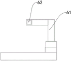
Furthermore, a limiting device is arranged between the clamping device and the cutting device and comprises a limiting hole, and the limiting hole is fixedly connected with the L-shaped supporting rod.
Compared with the prior art, this practical beneficial effect is:
through setting up stop device, can prevent that the power cord from squinting, through setting up the rotary rod, can outwards rotate the rotary rod and conveniently put the power cord on, through setting up the conveyer belt, can make the power cord that is cut away and remove, prevent that the power cord from piling up, improved the work efficiency of device.
Drawings
In order to more clearly illustrate the embodiments of the present application or the technical solutions in the prior art, the drawings needed to be used in the description of the embodiments or the prior art will be briefly introduced below, and it is obvious that the drawings in the following description are some embodiments of the present application, and it is obvious for those skilled in the art to obtain other drawings based on these drawings without creative efforts. Throughout the drawings, like elements or portions are generally identified by like reference numerals. In the drawings, elements or portions are not necessarily drawn to scale.
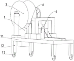
FIG. 1 is a schematic view of the overall appearance structure of the present invention;
FIG. 2 is a schematic view of the structure of the clamping device of the present invention;
FIG. 3 is a schematic structural view of the cutting device of the present invention;
fig. 4 is a schematic structural view of the mounting assembly of the present invention.
In the figure: 1. an apparatus body; 11. a base; 12. supporting legs; 13. a roller; 3. a clamping device; 31. A first fixed block; 32. a fixed shaft; 33. rotating the rod; 34. a gear; 35. a return spring; 36. a handle; 37. a threaded rod; 38. a support plate; 39. a second fixed block; 4. a cutting device; 41. a support; 42. An electric telescopic rod; 43. a blade; 44. cutting the table; 46. a guide groove; 47. a conveyor belt; 48. a baffle plate; 6. a limiting device; 61. a limiting hole; 62. l supporting rod.
Detailed Description
In the description of the present invention, it should be noted that the terms "upper", "lower", "inner", "outer", "front end", "rear end", "both ends", "one end", "the other end" and the like indicate orientations or positional relationships based on the orientations or positional relationships shown in the drawings, and are only for convenience of description and simplification of description, but do not indicate or imply that the device or element to which the reference is made must have a specific orientation, be constructed in a specific orientation, and be operated, and thus, should not be construed as limiting the present invention. Furthermore, the terms "first" and "second" are used for descriptive purposes only and are not to be construed as indicating or implying relative importance.
In the description of the present invention, it is to be noted that, unless otherwise explicitly specified or limited, the terms "mounted," "disposed," "connected," and the like are to be construed broadly, and for example, "connected" may be either fixedly connected or detachably connected, or integrally connected; can be mechanically or electrically connected; they may be connected directly or indirectly through intervening media, or they may be interconnected between two elements. The specific meaning of the above terms in the present invention can be understood as a specific case by those skilled in the art.
The technical solutions in the embodiments of the present invention will be described clearly and completely with reference to the accompanying drawings in the embodiments of the present invention, and it is obvious that the described embodiments are only some embodiments of the present invention, not all embodiments. All other embodiments obtained by persons skilled in the art based on the embodiments in the present application without any creative work belong to the protection scope of the present application.
Referring to fig. 1-4, the present invention provides a technical solution of a cutting device for processing and producing power lines: a cutting equipment for power line processing production comprises an equipment body 1, wherein the equipment body 1 comprises:
the base 11, four supporting legs 12 are arranged below the base 11, rollers 13 are arranged below the supporting legs 12, a clamping device 3 is arranged above the left side of the base 11, a fixing shaft 32 is arranged in front of the side surface of the clamping device 3, a rotating rod 33 is arranged above the fixing shaft 32, the rotating rod 33 penetrates through the fixing shaft 32 and is movably connected with the fixing shaft 32, a cutting device 4 is arranged above the middle of the base 11, the cutting device 4 is provided with a cutting table 44, a first fixing block 31 is arranged above the rotating rod 33, the first fixing block 31 is fixedly connected with the rotating rod 33, by arranging the rotating rod 33, the rotating rod 33 can be rotated outwards to conveniently put on a power line, the rotating rod 33 is provided with a gear 34, the gear 34 is movably connected with the rotating rod 33, the outer end of the rotating rod 33 is provided with a threaded rod 37, by arranging the threaded rod 37, power coils with different widths can be obtained according to the power coils, the threaded rod 37 is rotated, so that the distance between the two fixed blocks is changed, the working efficiency of the device is improved, the diameter of the threaded rod 37 is smaller than that of the rotating rod 33, the inside of the rotating rod 33 is hollow, the threaded rod 37 can enter the rotating rod 33, and the rotating rod 33 is movably connected with the threaded rod 37;
the inboard second fixed block 39 that is provided with of threaded rod 37, second fixed block 39 and threaded rod 37 swing joint, be provided with reset spring 35 and second fixed block 39 fixed connection on the outer stationary plane of second fixed block 39, the reset spring 35 other end is provided with backup pad 38, threaded rod 37 runs through backup pad 38 and with backup pad 38 threaded connection, threaded rod 37 outer end is provided with handle 36, cutting device 4 is provided with support 41, support 41 below is provided with electric telescopic handle 42, electric telescopic handle 42 below is provided with blade 43, cutting bed 44 left side is provided with guide way 46, guide way 46 left side is provided with conveyer belt 47, conveyer belt 47 both sides are provided with baffle 48, be provided with stop device 6 between clamping device 3 and the cutting device 4, stop device 6 includes spacing hole 62, spacing hole 62 and L bracing piece 61 fixed connection.
The utility model discloses a set up equipment body 1, before the use, the usable rotary rod 33 of user of service rotates outwards, put the power cord on, can be connected threaded rod 37 with rotary rod 33 through rotatory threaded rod 37, threaded rod 33 can play limiting displacement to rotary rod 37 in inserting rotary rod 37, elasticity that can utilize the spring through setting up reset spring 35 presss from both sides the power cord tightly, after fixing the power cord, through the manual pulling power cord of user of service, draw the assigned position, cut, the power cord after the cutting falls into on conveyer belt 47, prevent that table surface from piling up, the work efficiency of cutting has been improved, further strengthen the practicality of device.
Although embodiments of the present invention have been shown and described, it will be appreciated by those skilled in the art that changes, modifications, substitutions and alterations can be made in these embodiments without departing from the principles and spirit of the invention, the scope of which is defined in the appended claims and their equivalents.
Claims (8)
1. The utility model provides a cutting equipment is used in power cord processing production, includes equipment body (1), its characterized in that: the apparatus body (1) comprises:
the device comprises a base (11), wherein four supporting legs (12) are arranged below the base (11), and rollers (13) are arranged below the supporting legs (12);
the clamping device (3) is arranged above the left side of the base (11), a fixed shaft (32) is arranged in front of the side face of the clamping device (3), a rotating rod (33) is arranged above the fixed shaft (32), and the rotating rod (33) penetrates through the fixed shaft (32) and is movably connected with the fixed shaft (32);
cutting device (4), cutting device (4) set up in the centre top of base (11), cutting device (4) are provided with cutting bed (44).
2. The cutting equipment for processing and producing the power cord as claimed in claim 1, wherein: be provided with first fixed block (31) above rotary rod (33), first fixed block (31) and rotary rod (33) fixed connection, rotary rod (33) are provided with gear (34), gear (34) and rotary rod (33) swing joint.
3. The cutting equipment for processing and producing the power cord as claimed in claim 1, wherein: rotary rod (33) outer end is provided with threaded rod (37), threaded rod (37) diameter is less than rotary rod (33), rotary rod (33) is inside to be hollow, rotary rod (33) can be got into in threaded rod (37), rotary rod (33) and threaded rod (37) swing joint.
4. The cutting equipment for processing and producing the power cord as claimed in claim 3, wherein: the threaded rod (37) inboard is provided with second fixed block (39), second fixed block (39) and threaded rod (37) swing joint, be provided with reset spring (35) on the outer stationary plane of second fixed block (39).
5. The cutting equipment for processing and producing the power cord as claimed in claim 4, wherein: reset spring (35) and second fixed block (39) fixed connection, reset spring (35) other end is provided with backup pad (38), threaded rod (37) run through backup pad (38) and with backup pad (38) threaded connection, threaded rod (37) outer end is provided with handle (36).
6. The cutting equipment for processing and producing the power cord as claimed in claim 1, wherein: the cutting device (4) is provided with a support (41), an electric telescopic rod (42) is arranged below the support (41), and a blade (43) is arranged below the electric telescopic rod (42).
7. The cutting equipment for processing and producing the power cord as claimed in claim 1, wherein: cutting table (44) left side is provided with guide way (46), guide way (46) left side is provided with conveyer belt (47), conveyer belt (47) both sides are provided with baffle (48).
8. The cutting equipment for processing and producing the power cord as claimed in claim 1, wherein: be provided with stop device (6) between clamping device (3) and cutting device (4), stop device (6) are including spacing hole (62), spacing hole (62) and L bracing piece (61) fixed connection.
Priority Applications (1)
| Application Number | Priority Date | Filing Date | Title |
|---|---|---|---|
| CN202221025540.1U CN217432896U (en) | 2022-04-30 | 2022-04-30 | Cutting equipment is used in power cord processing production |
Applications Claiming Priority (1)
| Application Number | Priority Date | Filing Date | Title |
|---|---|---|---|
| CN202221025540.1U CN217432896U (en) | 2022-04-30 | 2022-04-30 | Cutting equipment is used in power cord processing production |
Publications (1)
| Publication Number | Publication Date |
|---|---|
| CN217432896U true CN217432896U (en) | 2022-09-16 |
Family
ID=83220166
Family Applications (1)
| Application Number | Title | Priority Date | Filing Date |
|---|---|---|---|
| CN202221025540.1U Active CN217432896U (en) | 2022-04-30 | 2022-04-30 | Cutting equipment is used in power cord processing production |
Country Status (1)
| Country | Link |
|---|---|
| CN (1) | CN217432896U (en) |
Cited By (1)
| Publication number | Priority date | Publication date | Assignee | Title |
|---|---|---|---|---|
| CN115570084A (en) * | 2022-11-24 | 2023-01-06 | 江苏创德电器线缆有限公司 | Fixed-length cutting device for power cables |
-
2022
- 2022-04-30 CN CN202221025540.1U patent/CN217432896U/en active Active
Cited By (2)
| Publication number | Priority date | Publication date | Assignee | Title |
|---|---|---|---|---|
| CN115570084A (en) * | 2022-11-24 | 2023-01-06 | 江苏创德电器线缆有限公司 | Fixed-length cutting device for power cables |
| CN115570084B (en) * | 2022-11-24 | 2023-03-14 | 江苏创德电器线缆有限公司 | Fixed-length cutting device for power cables |
Similar Documents
| Publication | Publication Date | Title |
|---|---|---|
| CN217432896U (en) | Cutting equipment is used in power cord processing production | |
| CN209986149U (en) | Automatic straightening device for metal wires | |
| CN111496312A (en) | Aluminum plate rapid cutting machine and using method thereof | |
| CN218414252U (en) | Magnetic core gum device | |
| CN211685999U (en) | Adhesive label attaching machine | |
| CN212470045U (en) | Cutting system is used in production of electric power iron tower | |
| CN209988840U (en) | Cutting device for packaging film production | |
| CN216543514U (en) | Stock form paper cutting equipment convenient to adjust size | |
| CN218365068U (en) | Virtual cutting machine of honeycomb paper | |
| CN218779214U (en) | Cutting device for processing polyester silk fabric | |
| CN216189619U (en) | Printing machine capable of automatically winding paper conveniently | |
| CN212884277U (en) | Tube coiling machine for processing pen container | |
| CN214686693U (en) | High-temperature environment adhesive tape sucking and cutting mechanism | |
| CN211761748U (en) | High-precision cutting machine for producing composite yoga mat | |
| CN221675340U (en) | Metal material drawing forming equipment | |
| CN218841229U (en) | Limiting mechanism of engraving machine | |
| CN218428649U (en) | Cutting device for producing heating film of automobile battery pack | |
| CN217545834U (en) | Motor stator slot with insulating paper is carried | |
| CN221658888U (en) | Polishing device for table tennis bat production | |
| CN221773633U (en) | Cutting equipment for milling cutter production | |
| CN216462559U (en) | Metal mesh welding equipment capable of improving feeding safety | |
| CN221289117U (en) | Plate rolling equipment applied to wind power tower barrel | |
| CN213795527U (en) | Multi-workpiece clamping multi-station rotatable pneumatic clamp device | |
| CN216266433U (en) | Cutting device convenient for fixing tool for rubber processing | |
| CN211218196U (en) | Transmission machine accessory processing folding device |
Legal Events
| Date | Code | Title | Description |
|---|---|---|---|
| GR01 | Patent grant | ||
| GR01 | Patent grant |