CN217402365U - One-way high-power LED center line lamp - Google Patents
One-way high-power LED center line lamp Download PDFInfo
- Publication number
- CN217402365U CN217402365U CN202220930518.5U CN202220930518U CN217402365U CN 217402365 U CN217402365 U CN 217402365U CN 202220930518 U CN202220930518 U CN 202220930518U CN 217402365 U CN217402365 U CN 217402365U
- Authority
- CN
- China
- Prior art keywords
- lens
- led lamp
- support piece
- top cap
- lamp
- Prior art date
- Legal status (The legal status is an assumption and is not a legal conclusion. Google has not performed a legal analysis and makes no representation as to the accuracy of the status listed.)
- Active
Links
Images


Landscapes
- Non-Portable Lighting Devices Or Systems Thereof (AREA)
Abstract
The utility model relates to a help navigation lamps and lanterns field, concretely relates to one-way high-power LED center line lamp. Including lower casing and top cap through bolted connection, the interior top surface of top cap is provided with two sets of lens support piece, lens are installed to lens support piece's rear side portion, set up the lens groove that link up with the top cap on the top cap, and cooperate with lens, the interior top surface of top cap still is provided with two sets of LED lamp support piece, be provided with the light source fixed plate on the LED lamp support piece, be provided with the heating panel on the light source fixed plate, be provided with the LED lamp on the heating panel, the LED lamp is located between lens and the heating panel. The LED lamp with high power is provided with an adjusting groove and a corresponding threaded hole, and the LED lamp with high power aims to solve the problems that an existing one-way LED lamp with high power on the market is low in power and cannot be used for correspondingly adjusting the irradiation range and the focusing brightness according to actual needs.
Description
Technical Field
The utility model relates to a help navigation lamps and lanterns field, concretely relates to high-power LED centerline lamp.
Background
The light source of the navigation light equipment mainly adopts traditional light sources such as incandescent lamps, halogen tungsten lamps, gas discharge lamps and the like, and novel light sources such as LED lamps and the like. The traditional light source has light color similar to white light, and light with different colors is obtained by adding a colored glass filter cover, so that the traditional light source is gradually replaced by novel light sources such as an LED lamp and the like due to the defects of short service life, large energy loss and the like. The LED has the advantages of small volume, light weight, less energy consumption, long service life, short response time, good shock resistance and the like. Meanwhile, the LED chips with different colors meet the requirements of navigational lights on light sources with different colors, and more importantly, the luminous efficiency of the LED is greatly improved in recent years so that the luminous efficiency of the LED is far higher than that of the traditional light source.
However, the power of the mainstream LED neutral line lamp in the market is basically about 10W, and the irradiation distance is short, which cannot meet the requirement. In addition, the irradiation range and focus of the existing LED neutral line lamp are certain, and the corresponding adjustment cannot be carried out according to the actual requirement.
SUMMERY OF THE UTILITY MODEL
The utility model provides an one-way high-power LED center line lamp is provided with powerful LED lamp to and be provided with adjustment tank and the screw hole that corresponds, it is low to aim at solving one-way high-power LED lamp power on the existing market, and can not realize the regulation of irradiation range and focus, can realize the function of high-power and wide angle, hi-lite.
In order to realize the technical effect, the utility model discloses the technical scheme who adopts as follows:
the utility model provides an one-way high-power LED center wire lamp, includes lower casing and top cap through bolted connection, the interior top surface of top cap is provided with two sets of lens support piece, lens are installed to lens support piece's back lateral part, set up the lens groove that link up with the top cap on the top cap, and cooperate with lens, the interior top surface of top cap still is provided with two sets of LED lamp support piece, be provided with the light source fixed plate on the LED lamp support piece, be provided with the heating panel on the light source fixed plate, be provided with the LED lamp on the heating panel, the LED lamp is located between lens and the heating panel.
Preferably, a first adjusting groove is formed in the bottom of the lens supporting piece, two first threaded holes corresponding to the first adjusting groove are formed in the inner top surface of the top cover, a second adjusting groove is formed in the bottom of the LED lamp supporting piece, two second threaded holes corresponding to the second adjusting groove are formed in the inner top surface of the top cover, and bolts are arranged in the first threaded holes and the second threaded holes.
Preferably, the length of the first adjusting groove is greater than the distance between the two first threaded holes, and the length of the second adjusting groove is greater than the distance between the two second threaded holes.
Preferably, three lamp fixing plates are formed on the lower end surface of the lower shell at equal intervals.
Preferably, a sealing ring is arranged between the lower shell and the top cover.
Compared with the prior art, the beneficial effects of the utility model are that:
1. the novel LED lamp with the maximum power of 90W is arranged, the problem that the LED lamp in the existing market is low in power is solved, meanwhile, the LED lamp has higher brightness, and the navigation requirement can be met;
2. this novel lens support piece and LED lamp support piece of being provided with can the back-and-forth movement with lens support piece and LED lamp support piece, and then can realize the calibration regulation of illumination angle to and the setting of required illumination angle, then be fixed in the screw hole with it through the bolt.
Drawings
The accompanying drawings are included to provide a further understanding of the invention, and are incorporated in and constitute a part of this specification, illustrate embodiments of the invention, and together with the description serve to explain the invention and not to limit the invention.
In the drawings:
fig. 1 is a schematic structural view of the present invention;
fig. 2 is a schematic structural view of the lower housing of the present invention;
FIG. 3 is a schematic view of the top cover of the present invention;
fig. 4 is a schematic structural view of the inverted top cover of the present invention;
fig. 5 is a top view of the top cover of the present invention;
FIG. 6 is an enlarged view of portion A of FIG. 5;
FIG. 7 is a schematic structural view of a lens according to the present invention;
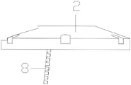
fig. 8 is a schematic structural view of the heat dissipating plate of the present invention;
fig. 9 is a front view of the top cover of the present invention;
fig. 10 is a schematic structural view of the LED lamp arrangement of the present invention;
wherein: 1. the LED lamp comprises a lower shell, 2 parts of a top cover, 3 parts of an LED lamp, 4 parts of a lens, 5 parts of a cooling fin, 6 parts of a lens supporting piece, 7 parts of an LED lamp supporting piece, 8 parts of a cooling plate, 9 parts of a light source fixing plate, 10 parts of top cover threaded holes, 11 parts of a lamp fixing plate, 12 parts of cable holes, 13 parts of lower shell threaded holes, 14 parts of a first adjusting groove, 15 parts of a first threaded hole, 16 parts of a second threaded hole and 17 parts of a second adjusting groove.
Detailed Description
The preferred embodiments of the present invention will be described in conjunction with the accompanying drawings, and it will be understood that they are presented herein only to illustrate and explain the present invention, and not to limit the present invention.
Example (b):
referring to the attached drawings 1-10, the unidirectional high-power LED centerline lamp comprises a lower shell 1 and a top cover 2 which are connected through bolts, wherein a sealing ring is arranged between the lower shell 1 and the top cover 2, a plurality of top cover threaded holes 10 are formed in the top cover 2, lower shell threaded holes 13 matched with the top cover threaded holes 10 are correspondingly formed in the edge of the lower shell 1, bolts are arranged in the top cover threaded holes 10 and the lower shell threaded holes 13, and the lower shell 1 and the top cover 2 are fixedly connected.
The inner top surface of the top cover 2 is provided with two groups of lens supporting pieces 6, the bottom of each lens supporting piece 6 is provided with a first adjusting groove 14, the rear side part of each lens supporting piece 6 is provided with a threaded hole, and then the lens 4 is installed on the lens supporting pieces 6 through bolts.
The top cover 2 is provided with a lens groove communicated with the top cover 2 and matched with the lens 4, so that the LED light focused by the lens 4 can be irradiated without shielding, and meanwhile, the lens 4 can be protected.
The interior top surface of top cap 2 is provided with two sets of LED lamp support piece 7, second adjustment tank 17 has been seted up to LED lamp support piece 7's bottom, threaded hole has been seted up to LED lamp support piece 7's back lateral part, installs light source fixing plate 9 on LED lamp support piece 7 through the bolt, set up a plurality of screw on the light source fixing plate 9, be fixed in light source fixing plate 9 with heating panel 8 through the bolt on, be provided with a plurality of fin 5 on the heating panel 8, can increase radiating effect. The heat dissipation plate 8 can dissipate heat of the LED lamp, and lamp damage caused by heat accumulation is avoided.
Two first screw holes 15 corresponding to the first adjusting grooves 14 are formed in the inner top surface of the top cover 2, two second screw holes 16 corresponding to the second adjusting grooves 17 are formed in the inner top surface of the top cover 2, bolts are arranged in the first screw holes 15 and the second screw holes 16, and therefore the lens support piece 6 and the LED lamp support piece 7 are fixed on the inner top surface of the top cover 2.
The length of the first adjusting groove 14 is greater than the distance between the two first threaded holes 15, and the length of the second adjusting groove 17 is greater than the distance between the two second threaded holes 16, so that the lens support member 6 and the LED lamp support member 7 can move forwards and backwards.
During the use, through with lens support piece 6 and LED lamp support piece 7 back-and-forth movement to suitable position, then fasten the bolt in first screw hole 15 and second screw hole 16, and then realize the fixed to lens support piece 6 and LED lamp support piece 7 to and realize the regulation to lens 4 apart from LED lamp distance, and then realize the calibration regulation of illumination angle, and the setting of required illumination angle, then be fixed in the screw hole with it through the bolt.
The lower end face of the lower shell 1 is provided with three lamp fixing plates 11 at equal intervals, and the lamp fixing plates can be externally connected to the body equipment through bolts.
The side wall of the lower shell 1 is provided with a cable hole 12, and a cable connected with the LED lamp 3 penetrates through the cable hole 12 to be connected with an external power supply.
The utility model discloses in, the relative distance of light-emitting window light beam can be through adjusting lens support piece 6 and LED lamp support piece 7, realizes the focus of more wide range shining or luminance, and then is adapted to more scene demands. The maximum power of the lamp is 90W, the maximum light intensity in an irradiation range is 12000cd under the power, and the visible distance is better than 5 km.
The utility model discloses principle and use flow:
during the use, assemble each subassembly in proper order and accomplish, when the scope that needs luminance and shine, loosen the bolt in first screw hole 15 and the second screw hole 16, lens support piece 6 and LED lamp support piece 7 are close to each other, reach the best focus distance after, will realize the regulation of strongest luminance. By moving the lens support 6 and the LED lamp support 7 away from each other, a greater range of divergent illumination is achieved, with a greater range of illumination.
The foregoing shows and describes the general principles, essential features, and advantages of the invention. It will be understood by those skilled in the art that the present invention is not limited to the above embodiments, and that the foregoing embodiments and descriptions are provided only to illustrate the principles of the present invention without departing from the spirit and scope of the present invention. The scope of the invention is defined by the appended claims and equivalents thereof.
Claims (5)
1. The utility model provides a one-way high-power LED center line lamp, includes lower casing (1) and top cap (2) through bolted connection, its characterized in that: the utility model discloses a LED lamp, including top cap (2), lens support piece (6), lens (4) are installed to the back lateral part of lens support piece (6), set up the lens groove that link up with top cap (2) on top cap (2), and cooperate with lens (4), the interior top surface of top cap (2) still is provided with two sets of LED lamp support piece (7), be provided with light source fixed plate (9) on LED lamp support piece (7), be provided with heating panel (8) on light source fixed plate (9), be provided with LED lamp (3) on heating panel (8), LED lamp (3) are located between lens (4) and heating panel (8).
2. The unidirectional high power LED centerline lamp of claim 1, wherein: first adjustment tank (14) have been seted up to the bottom of lens support piece (6), two first screw hole (15) that correspond with first adjustment tank (14) have been seted up to the interior top surface of top cap (2), second adjustment tank (17) have been seted up to the bottom of LED lamp support piece (7), two second screw hole (16) that correspond with second adjustment tank (17) have been seted up to the interior top surface of top cap (2), all be provided with the bolt in first screw hole (15) and the second screw hole (16).
3. The unidirectional high power LED centerline light of claim 2, wherein: the length of the first adjusting groove (14) is larger than the distance between the two first threaded holes (15), and the length of the second adjusting groove (17) is larger than the distance between the two second threaded holes (16).
4. The unidirectional high power LED centerline lamp of claim 1, wherein: the lower end face of the lower shell (1) is provided with three lamp fixing plates (11) at equal intervals.
5. The unidirectional high power LED centerline light of claim 1, wherein: and a sealing ring is arranged between the lower shell (1) and the top cover (2).
Priority Applications (1)
| Application Number | Priority Date | Filing Date | Title |
|---|---|---|---|
| CN202220930518.5U CN217402365U (en) | 2022-04-21 | 2022-04-21 | One-way high-power LED center line lamp |
Applications Claiming Priority (1)
| Application Number | Priority Date | Filing Date | Title |
|---|---|---|---|
| CN202220930518.5U CN217402365U (en) | 2022-04-21 | 2022-04-21 | One-way high-power LED center line lamp |
Publications (1)
| Publication Number | Publication Date |
|---|---|
| CN217402365U true CN217402365U (en) | 2022-09-09 |
Family
ID=83142416
Family Applications (1)
| Application Number | Title | Priority Date | Filing Date |
|---|---|---|---|
| CN202220930518.5U Active CN217402365U (en) | 2022-04-21 | 2022-04-21 | One-way high-power LED center line lamp |
Country Status (1)
| Country | Link |
|---|---|
| CN (1) | CN217402365U (en) |
-
2022
- 2022-04-21 CN CN202220930518.5U patent/CN217402365U/en active Active
Similar Documents
| Publication | Publication Date | Title |
|---|---|---|
| CN101893180B (en) | LED lamp bulb | |
| CN101373055A (en) | High-power LED road lamp | |
| US20120051055A1 (en) | Retrofit system for converting an existing luminaire into a solid state lighting luminaire | |
| CN217402365U (en) | One-way high-power LED center line lamp | |
| RU166928U1 (en) | LED LAMP | |
| CN105351856A (en) | LED (light-emitting diode) locomotive headlamp | |
| CN205579513U (en) | Can wholly radiating high -power LED lamps and lanterns structure | |
| CN201391777Y (en) | Big power LED lamp | |
| CN107883262A (en) | A kind of LED bay light | |
| CN209944228U (en) | Integral heat dissipation positioner of LED car headlight | |
| CN207729318U (en) | A kind of LED bay light | |
| CN208295573U (en) | A kind of LED light device | |
| CN202674981U (en) | Double-light-source multipurpose LED (Light Emitting Diode) lamp | |
| RU160784U1 (en) | LED PROJECT LAMP | |
| CN212005249U (en) | Novel LED lamp structure | |
| CN101813276A (en) | Environment friendly high-power LED street lamp | |
| CN206786468U (en) | A kind of anti-dazzle LED spotlight | |
| CN105003868A (en) | LED streetlamp module | |
| CN213930763U (en) | Lighting structure for car lamp | |
| CN109854968A (en) | A kind of LED light source of alternative high-pressure sodium lamp | |
| CN208041777U (en) | A kind of tunable radiation emitting angle track shot-light | |
| CN220728015U (en) | Square double-direct-irradiation double-light lens | |
| CN210373105U (en) | LED lamp with high-efficient heat dissipation | |
| CN220169402U (en) | High heat dissipation cup lamps and lanterns that adjust luminance | |
| CN108679467A (en) | A kind of LED light device |
Legal Events
| Date | Code | Title | Description |
|---|---|---|---|
| GR01 | Patent grant | ||
| GR01 | Patent grant |