CN217382629U - Anti-dazzling lamp convenient to mount and used in classroom - Google Patents
Anti-dazzling lamp convenient to mount and used in classroom Download PDFInfo
- Publication number
- CN217382629U CN217382629U CN202122663887.0U CN202122663887U CN217382629U CN 217382629 U CN217382629 U CN 217382629U CN 202122663887 U CN202122663887 U CN 202122663887U CN 217382629 U CN217382629 U CN 217382629U
- Authority
- CN
- China
- Prior art keywords
- limiting plate
- spliced pole
- installing support
- cap
- classroom
- Prior art date
- Legal status (The legal status is an assumption and is not a legal conclusion. Google has not performed a legal analysis and makes no representation as to the accuracy of the status listed.)
- Active
Links
Images



Landscapes
- Non-Portable Lighting Devices Or Systems Thereof (AREA)
Abstract
The utility model discloses a be convenient for installation of classroom usefulness prevent dazzling lamps and lanterns, below including the installing support is provided with the lamps and lanterns body, be provided with installation mechanism on the installing support, installation mechanism includes the spliced pole, limiting plate and rotation cap, the limiting plate is located the spliced pole, the limiting plate is located the below of installing support, it is located the bottom of spliced pole to rotate the cap, the mounting groove has been seted up at the middle part of installing support, the spliced pole is located the inner chamber of mounting groove, the equal fixedly connected with extrusion post of both sides side sides of rotation cap top, the top fixedly connected with extrusion pad of extrusion post, the extrusion pad is laminated mutually with the limiting plate, the bottom of spliced pole is equipped with and rotates cap matched with external screw thread. The utility model discloses an utilize mutually supporting of installing support, spliced pole, limiting plate, rotation cap, spliced pole and extrusion pad, the top and the wall body of spliced pole are connected, and the limiting plate is injectd the position of installing support, and then is favorable to installing and dismantling installing support and lamps and lanterns body.
Description
Technical Field
The utility model relates to a lamps and lanterns field, in particular to be convenient for installation of anti-dazzle lamps and lanterns that classroom was used.
Background
The lamp is an appliance capable of transmitting light, distributing and changing light distribution of a light source, and comprises all parts required for fixing and protecting the light source except the light source and circuit accessories required for connecting with a power supply, modern lamps comprise household lighting, commercial lighting, industrial lighting, road lighting, landscape lighting, special lighting and the like, the household lighting is developed from the earliest incandescent bulbs of electricity, fluorescent tubes, energy-saving lamps, halogen tungsten lamps, gas discharge lamps, LED special material lighting and the like, and most of all lighting lamps are developed under the development of the light sources, such as lamp holders, fluorescent lamp supports, various technical decorative lighting and the like.
The variety of lamps and lanterns is various, and the lamps and lanterns of using in classroom need have the characteristics of preventing dazzling, and classroom lamps and lanterns are when installing, utilize installing support and classroom lamps and lanterns to install usually, then reuse the bolt to be connected installing support and wall body, but the possibility of rust can appear in the bolt, and the maintenance is dismantled to classroom lamps and lanterns to this kind of mode not convenient for, has certain limitation.
SUMMERY OF THE UTILITY MODEL
An object of the utility model is to provide a be convenient for installation of classroom usefulness prevents dazzling lamps and lanterns to solve the problem that provides among the above-mentioned background art.
In order to achieve the above object, the utility model provides a following technical scheme: an anti-dazzling lamp convenient to mount for a classroom comprises a mounting bracket, wherein a lamp body is arranged below the mounting bracket, and a mounting mechanism is arranged on the mounting bracket;
the mounting mechanism comprises a connecting column, a limiting plate and a rotating cap, the limiting plate is located on the connecting column, the limiting plate is located below the mounting bracket, the rotating cap is located at the bottom end of the connecting column, a mounting groove is formed in the middle of the mounting bracket, and the connecting column is located in the inner cavity of the mounting groove.
Preferably, the both sides on rotation cap top all fixedly connected with extrusion post, the top fixedly connected with extrusion pad of extrusion post, the top and the spacing board laminating of extrusion pad.
Preferably, the bottom of the connecting column is provided with an external thread matched with the rotating cap, and the bottom of the connecting column is in threaded insertion connection with the inner cavity of the rotating cap.
Preferably, the middle part of the limiting plate is provided with a rotating groove, and the connecting column is rotatably inserted and connected with the inner cavity of the rotating groove.
Preferably, the outer wall fixed interlude of spliced pole is connected with two solid fixed rings, two gu fixed ring is located the top and the below of limiting plate respectively, the equal fixedly connected with dead lever in both sides of rotating the cap.
Preferably, the top of the mounting bracket is symmetrically provided with positioning grooves, and limiting columns are arranged inside the positioning grooves.
The utility model discloses a technological effect and advantage:
(1) the utility model discloses an utilize mutually supporting of installing support, spliced pole, limiting plate, rotation cap, spliced pole and extrusion pad, the top and the wall body of spliced pole are connected, and the limiting plate is injectd the position of installing support, and then is favorable to installing and dismantling installing support and lamps and lanterns body;
(2) the utility model discloses an utilize mutually supporting of spacing post, constant head tank and solid fixed ring, spacing post and constant head tank are favorable to prescribing a limit to the position of installing support, avoid the installing support installation after slide at will, gu fixed ring is favorable to prescribing a limit to the position of limiting plate, is convenient for make the limiting plate rotate steadily.
Drawings
Fig. 1 is a schematic view of the explosion structure at the mounting bracket of the present invention.
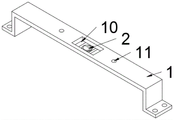
Fig. 2 is the structure diagram of the mounting bracket of the present invention.
Fig. 3 is the front sectional structural schematic diagram of the mounting bracket of the present invention.
Fig. 4 is the side sectional structure schematic diagram of the mounting bracket of the present invention.
In the figure: 1. mounting a bracket; 2. connecting columns; 3. a limiting plate; 4. rotating the cap; 5. extruding the column; 6. a pressing pad; 7. a fixing ring; 8. a fixing rod; 9. a limiting post; 10. mounting grooves; 11. positioning a groove; 12. the lamp body.
Detailed Description
The technical solutions in the embodiments of the present invention will be described clearly and completely with reference to the drawings in the embodiments of the present invention, and it is obvious that the described embodiments are only some embodiments of the present invention, not all embodiments. Based on the embodiments in the present invention, all other embodiments obtained by a person skilled in the art without creative work belong to the protection scope of the present invention.
The utility model provides a be convenient for anti-dazzle lamps and lanterns of installation that classroom was used as shown in fig. 1-4, including installing support 1, installing support 1's below is provided with lamps and lanterns body 12, and lamps and lanterns body 12 includes the lamp body, drive power supply, aluminium base board light source, the diffuser plate, grid plate and filter frame, drive power supply is located the below of lamp body, contains the lamp pearl in the aluminium base board light source, and aluminium base board light source is located drive power supply's below, and aluminium base board light source is located the top of diffuser plate, and grid plate is located the below of diffuser plate, and filter frame is located grid plate's below, is provided with installation mechanism on installing support 1.
The mounting mechanism comprises a connecting column 2, a limiting plate 3 and a rotating cap 4, wherein the connecting column 2 is favorable for being connected with a wall body, the mounting bracket 1 is convenient to mount, and further the lamp body 12 is favorable for being mounted, the limiting plate 3 is favorable for limiting the position of the mounting bracket 1, and the lamp body 12 is convenient to mount and dismount, the limiting plate 3 rotates circularly by taking the connecting column 2 as the center of circle, so that the limiting plate 3 is conveniently and slidably inserted into the inner cavity of the mounting groove 10, the mounting bracket 1 is favorable for being dismounted, the rotating cap 4 is favorable for limiting the position of the limiting plate 3, the stability of the limiting plate 3 is convenient to be increased, the limiting plate 3 is prevented from rotating randomly, the limiting plate 3 is positioned on the connecting column 2, the limiting plate 3 is positioned below the mounting bracket 1, the rotating cap 4 is positioned at the bottom end of the connecting column 2, the mounting groove 10 is formed in the middle part of the mounting bracket 1, and the length of the inner wall of the mounting groove 10 is greater than that of the limiting plate 3, the width of the inner wall of the mounting groove 10 is larger than that of the limiting plate 3, and the connecting column 2 is located in the inner cavity of the mounting groove 10.
The equal fixedly connected with of both sides side of rotating 4 tops of cap is equipped with the dummy club 5, is favorable to driving the dummy club 6 and moves, and the top fixedly connected with dummy club 6 of dummy club 5, dummy club 6 are favorable to extrudeing limiting plate 3, are convenient for prescribe a limit to the position of limiting plate 3, and the top and the limiting plate 3 of dummy club 6 are laminated mutually.
The bottom of spliced pole 2 is equipped with and rotates cap 4 matched with external screw thread, and the bottom of spliced pole 2 and the inner chamber screw thread alternate connection of rotating cap 4.
The middle part of the limiting plate 3 is provided with a rotating groove, and the connecting column 2 is rotatably and alternately connected with the inner cavity of the rotating groove.
The outer wall fixed interlude of spliced pole 2 is connected with two solid fixed rings 7, is favorable to prescribing a limit to the position of limiting plate 3, is convenient for make the steady rotation of limiting plate 3, and two solid fixed rings 7 are located the top and the below of limiting plate 3 respectively, rotate the equal fixedly connected with dead lever 8 in both sides of cap 4, are favorable to driving and rotate cap 4 and rotate, are convenient for operate rotating cap 4.
The constant head tank 11 has been seted up to the symmetry at the top of installing support 1, is favorable to fixing a position installing support 1, and the inside of constant head tank 11 is provided with spacing post 9, is favorable to prescribing a limit to the position of installing support 1, avoids installing support 1 to slide at will.
The utility model discloses theory of operation:
when the lamp body 12 needs to be installed, the top ends of the connecting column 2 and the limiting column 9 are installed with a wall body, then the installing support 1 and the lamp body 12 are installed by using external installing screws, then the installing support 1 and the connecting column 2 are connected, the limiting plate 3, the connecting column 2 and the inner cavity of the installing groove 10 are inserted in a sliding mode, then the limiting plate 3 is rotated, the limiting plate 3 rotates on the connecting column 2, the connecting column 2 rotates in the inner cavity of the rotating groove, then the limiting plate 3 rotates to ninety degrees, the limiting plate 3 rotates between the two fixing rings 7, the length of the rotating limiting plate 3 is larger than the width of the inner wall of the installing groove 10, the position of the installing support 1 is limited, the limiting column 9 is inserted in the inner cavity of the positioning groove 11 in a sliding mode, then the rotating cap 4 is connected with the connecting column 2, the connecting column 2 is connected with the inner cavity of the rotating cap 4 in a threaded mode, then the extrusion post 5 drives the extrusion pad 6 to move, so that the extrusion pad 6 is tightly attached to the bottom end of the limiting plate 3, the position of the limiting plate 3 is limited, and the installation of the lamp body 12 can be completed.
Finally, it should be noted that: although the present invention has been described in detail with reference to the foregoing embodiments, those skilled in the art can still modify the technical solutions described in the foregoing embodiments or make equivalent substitutions on some technical features, and any modifications, equivalent substitutions, improvements, etc. made within the spirit and principles of the present invention should be included in the scope of the present invention.
Claims (6)
1. An anti-glare lamp convenient to mount in a classroom comprises two mounting brackets (1), and is characterized in that a lamp body (12) is arranged below the mounting brackets (1), and a mounting mechanism is arranged on each mounting bracket (1);
installation mechanism includes spliced pole (2), limiting plate (3) and rotates cap (4), limiting plate (3) are located spliced pole (2), limiting plate (3) are located the below of installing support (1), it is located the bottom of spliced pole (2) to rotate cap (4), mounting groove (10) have been seted up at the middle part of installing support (1), spliced pole (2) are located the inner chamber of mounting groove (10).
2. The anti-glare lamp convenient to mount for the classroom as claimed in claim 1, wherein the two sides of the top end of the rotating cap (4) are fixedly connected with extrusion columns (5), the top ends of the extrusion columns (5) are fixedly connected with extrusion pads (6), and the top ends of the extrusion pads (6) are attached to the limiting plate (3).
3. An anti-glare lamp convenient to mount for classrooms, as claimed in claim 1, wherein the bottom of the connecting column (2) is provided with external threads matched with the rotating cap (4), and the bottom of the connecting column (2) is in threaded insertion connection with the inner cavity of the rotating cap (4).
4. The anti-glare lamp convenient to mount for the classroom as claimed in claim 1, wherein the middle of the limiting plate (3) is provided with a rotating groove, and the connecting column (2) is rotatably inserted into the inner cavity of the rotating groove.
5. The anti-glare lamp convenient to install for the classroom according to claim 1, wherein two fixing rings (7) are fixedly inserted and connected to the outer wall of the connecting column (2), the two fixing rings (7) are respectively located above and below the limiting plate (3), and fixing rods (8) are fixedly connected to both sides of the rotating cap (4).
6. The anti-glare lamp convenient to mount for the classroom as claimed in claim 1, wherein the top of the mounting bracket (1) is symmetrically provided with positioning grooves (11), and the positioning grooves (11) are internally provided with limiting columns (9).
Priority Applications (1)
| Application Number | Priority Date | Filing Date | Title |
|---|---|---|---|
| CN202122663887.0U CN217382629U (en) | 2021-11-02 | 2021-11-02 | Anti-dazzling lamp convenient to mount and used in classroom |
Applications Claiming Priority (1)
| Application Number | Priority Date | Filing Date | Title |
|---|---|---|---|
| CN202122663887.0U CN217382629U (en) | 2021-11-02 | 2021-11-02 | Anti-dazzling lamp convenient to mount and used in classroom |
Publications (1)
| Publication Number | Publication Date |
|---|---|
| CN217382629U true CN217382629U (en) | 2022-09-06 |
Family
ID=83084710
Family Applications (1)
| Application Number | Title | Priority Date | Filing Date |
|---|---|---|---|
| CN202122663887.0U Active CN217382629U (en) | 2021-11-02 | 2021-11-02 | Anti-dazzling lamp convenient to mount and used in classroom |
Country Status (1)
| Country | Link |
|---|---|
| CN (1) | CN217382629U (en) |
-
2021
- 2021-11-02 CN CN202122663887.0U patent/CN217382629U/en active Active
Similar Documents
| Publication | Publication Date | Title |
|---|---|---|
| CN211399530U (en) | Easy dismouting is convenient for change down lamp of light source | |
| US20110031870A1 (en) | Convenient-used Energy-saving ceiling lamp | |
| CN217382629U (en) | Anti-dazzling lamp convenient to mount and used in classroom | |
| CN213840671U (en) | Efficient multichannel dimmable LED lamp | |
| CN213453513U (en) | Energy-saving lamp convenient to replace | |
| CN212132188U (en) | LED lamp convenient to dismouting | |
| CN207796671U (en) | A kind of eye-protecting type environmental protection energy-saving lamp | |
| CN213272511U (en) | Adjustable lamp | |
| CN216844188U (en) | Novel ball bubble lamp heat radiation structure | |
| CN213453161U (en) | Novel small-size LED lamps and lanterns | |
| CN111963953A (en) | LED decorative ceiling lamp | |
| CN215722844U (en) | Indoor LED ceiling lamp device | |
| CN212746108U (en) | Anti-dazzle lampshade | |
| CN215808171U (en) | Lamp shade capable of adjusting irradiation angle and convenient to move | |
| CN209084576U (en) | A kind of new pattern laser lamp for stage | |
| CN203477944U (en) | Led illuminating lamp | |
| CN216952799U (en) | Ceiling lamp convenient to installation | |
| CN214501022U (en) | Ceiling lamp convenient to change lamps and lanterns | |
| CN220892064U (en) | LED factory lamp with multiple installation modes | |
| CN214669972U (en) | Quantum dot backlight unit convenient to installation | |
| CN214405662U (en) | High and good heat dissipation's of security LED lamp | |
| CN217356556U (en) | Lamp with high lighting effect and capable of being spliced | |
| CN217875414U (en) | Assembled LED illumination lamps and lanterns | |
| CN218209404U (en) | Quick-release lamp structure | |
| CN211780533U (en) | Double-tube reflection type fluorescent lamp capable of mixing color and adjusting light |
Legal Events
| Date | Code | Title | Description |
|---|---|---|---|
| GR01 | Patent grant | ||
| GR01 | Patent grant |