CN203477944U - Led illuminating lamp - Google Patents
Led illuminating lamp Download PDFInfo
- Publication number
- CN203477944U CN203477944U CN201320496748.6U CN201320496748U CN203477944U CN 203477944 U CN203477944 U CN 203477944U CN 201320496748 U CN201320496748 U CN 201320496748U CN 203477944 U CN203477944 U CN 203477944U
- Authority
- CN
- China
- Prior art keywords
- radiator
- lamp
- led illuminating
- illuminating lamp
- fixed head
- Prior art date
- Legal status (The legal status is an assumption and is not a legal conclusion. Google has not performed a legal analysis and makes no representation as to the accuracy of the status listed.)
- Expired - Fee Related
Links
Images


Landscapes
- Non-Portable Lighting Devices Or Systems Thereof (AREA)
- Arrangement Of Elements, Cooling, Sealing, Or The Like Of Lighting Devices (AREA)
Abstract
The utility model relates to the technical field of LED illumination, in particular to an LED illumination lamp which is low in energy consumption, adjustable in angle and efficient in heat dissipation. The LED illumination lamp comprises a lamp holder and a radiator. The radiator is provided with a light-emitting light source. A through hole is formed in the middle of the radiator. A fan is arranged on the lamp holder. An exhaust port of the fan corresponds to the through hole. The LED illuminating lamp is good in heat dissipating effect and simple in heat dissipating structure, the angle can be freely adjusted, and the interchangeability can be met.
Description
[technical field]
The utility model relates to LED lighting technical field, particularly a kind of low energy consumption, and angle is adjustable, and efficient LED illuminating lamp dispels the heat.
[background technology]
Nowadays along with the development process of modernization China, the also modernization gradually of the emerging product of all trades and professions.With regard to by illuminating industry, bulb before, incandescent lamp, fluorescent lamp updates gradually as modern electricity-saving lamp, the lighting of the more energy-conservation environmental protection more such as LED lamp.Follow further going deep into of scientific and technical development and application practice, LED lighting engineering has become the lighting engineering most popular, the most promising, acceptance level is the highest.
But, due to the technical field of LED illumination in recent years just rising gradually, the technical barrier that its application under various environment also has many needs to assault fortified position.Such as, how low-power LED lamp is replaced to the high-pressure mercury lamp of high-power, the super high power of present outdoor application, Projecting Lamp, the products such as Landscape Lamp.The environment using due to high-pressure mercury lamp is all to need high brightness, high-power, lighting demand on a large scale, so if directly adopt the LED outdoor illuminating lamp under technical conditions now will cause caloric value too large, the service life of reducing whole light fixture.Add, the light fixtures such as Landscape Lamp, Projecting Lamp are all in outdoor application, and for rain-proof dust-proof, its outside is all provided with seal closure, if it is bad to dispel the heat, also can reduce greatly the service life of whole light fixture.In summary, when LED light fixture and outdoor illuminating lamp Alternate, heat dissipation problem is crucial, must overcome.
In addition, a lot of outdoor illuminating lamps are not the environment setting of 360 ° of all-directional illuminations in use, but are placed on bottom surface or certain corner be take low-angle centralized lighting as main, adopt a plurality of these type of light fixtures to carry out all-directional illumination appointed area.Outdoor illuminating lamp like that, its irradiating angle only has when mounted and could determine, so if the direction of illumination that the light fixture of producing is fixed angle can not meet this environment for use.Therefore,, when LED light fixture and outdoor illuminating lamp Alternate, angle is adjustable is also a technical problem that must overcome.
In sum, for the LED light fixture of low energy consumption can being applied under the outdoor environment of high-power demand, the technical barrier that don't fail to overcome heat radiation and angle adjustment, just can be generalized to life-span length, low energy consumption, pollution-free LED lighting in the applied environment of outdoor lighting gradually.
[utility model content]
Bad for overcoming the heat radiation that existing LED lighting Alternate runs into when the outdoor lighting, light angle is non-adjustable, the technical barrier that service life is short, the utility model provides a kind of good heat dissipation effect, radiator structure is simple, angle can freely be adjusted, and meets the LED illuminating lamp of interchangeability.
The scheme of the utility model technical solution problem is to provide a kind of LED illuminating lamp, it comprises a lamp holder and a radiator, and illuminating source is installed on radiator, and there is a through hole at the middle part of this radiator, on this lamp holder, have a fan, the exhaust outlet of this fan is to should through hole.
Preferably, this radiator is a tubulose, and this illuminating source is fixed in the tubular surface of radiator.
Preferably, at least one radiating fin is set in the tubular surface of this radiator, this radiating fin is arranged along radiator axially parallel.
Preferably, on this lamp holder, be provided with angle-adjusting mechanism, this angle-adjusting mechanism is fixedly connected with this radiator.
Preferably, this angle-adjusting mechanism comprises the first interlock body and the second interlock body, the relatively independent rotation of these two interlock bodies, and the first interlock body is positioned on lamp holder, and the second interlock body is fixed on radiator.
Preferably, the rotational angle of relative the second interlock body of the first interlock body is 0-350 °.
Preferably, on the first interlock body, be provided with a spacing preiection, on the second interlock body, be provided with a limiting stand, spacing preiection is synchronizeed and is rotated with the first interlock body, and limiting stand is synchronizeed and rotated with the second interlock body.
Preferably, this lamp holder comprises a joint, a lampshade, and a plate, this joint screw thread connects this lampshade, and this connecting plate is fixed on this lampshade.
Preferably, a fixed head is set on connecting plate, this fan is fixed on this fixed head, and this fixed head is fixedly connected with this radiator, and this fixed head can independence and freedom rotate on this connecting plate.
Preferably, this fixed head is placed in the circular trough of this connecting plate, has a limiting stand in circular trough, has a spacing preiection on fixed head, after this limiting stand contacts with this spacing preiection, and fixed head one-way stop.
Compared with prior art, LED illuminating lamp of the present utility model adopts heat-pipe radiator as its heat abstractor, and simultaneously by fan, accelerate flowing of heat in whole light fixture, so its radiating rate and radiating effect are all better than present high-power LED outdoor lighting lamp.In addition, the the first interlock body forming by joint, lampshade, connecting plate, and the independent rotation angle adjustment mechanism between the second interlock body that fan, fixed head and radiator form, freely adjust the lighting angle of lamp body, can realize the angle adjustment scope of 0-350 °, and only need hold lamp body while adjusting and rotate to suitable position, operate very simple and convenient.Finally, the screwed union that the joint of the utility model LED illuminating lamp is standard universal, when LED illuminating lamp is replaced to the outdoor large-power lamp of present use, only need disassemble the light fixture that needs replacing, this LED illuminating lamp is screwed in the jack of standard, change very simple and conveniently, expanded greatly the application of this LED illuminating lamp.
[accompanying drawing explanation]
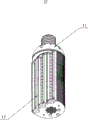
Fig. 1 is the perspective view of the utility model LED illuminating lamp.
Fig. 2 is the solid blast structural representation of the utility model LED illuminating lamp, and it comprises lamp holder and lamp body.
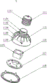
Fig. 3 is the solid blast structural representation of Fig. 2 lamp holder, and it comprises fixed head and connecting plate.
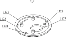
Fig. 4 is the first visual angle perspective view of fixed head shown in Fig. 3.
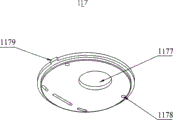
Fig. 5 is the second visual angle perspective view of fixed head shown in Fig. 3.
Fig. 6 is the first visual angle perspective view of connecting plate shown in Fig. 3.
Fig. 7 is the second visual angle perspective view of connecting plate shown in Fig. 3.
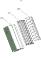
Fig. 8 is the solid blast structural representation of lamp body shown in Fig. 2.
Fig. 9 is the first visual angle perspective view of lamp body shown in Fig. 8.
Figure 10 is the second visual angle perspective view of lamp body shown in Fig. 8.
Figure 11 is the assembled relation perspective view of the utility model LED illuminating lamp.
[specific embodiment]
In order to make the purpose of this utility model, technical scheme and advantage are clearer, below in conjunction with accompanying drawing and embodiment, the utility model are further elaborated.Should be appreciated that specific embodiment described herein is only in order to explain the utility model, and be not used in restriction the utility model.
Refer to Fig. 1 and Fig. 2, the utility model LED illuminating lamp 10 comprises lamp holder 11 and lamp body 13, and lamp holder 11 is as attaching parts one end and power supply conducting, and the other end is electrically connected this lamp body 13, is fixedly connected with again with these lamp body 13 mechanical types simultaneously.Lamp body 13 throws light on as luminous component.After lamp holder 11 fits together with lamp body 13, conventionally use under outdoor environment, therefore the protective cover of a sealing is set in its periphery.
Refer to Fig. 3, lamp holder 11 comprises joint 111, lampshade 113, fan 115, fixed head 117 and connecting plate 119.On position relationship, joint 111 is positioned at one end, then sets gradually lampshade 113, fan 115, and fixed head 117 and connecting plate 119, connecting plate 119 is positioned at the other end.While fitting together, joint 111 is connected to the top of lampshade 113, and fan 115, fixed head 117 are contained in lampshade 113 inside with connecting plate 119.
Lampshade 113 comprises that one is positioned at cover body 1133 and the lampshade joint 1131 at top, the one-body molded top at cover body 1133 of lampshade joint 1131.On lampshade joint 1131, be provided with the joint screw thread matching with joint 111 internal whorls.Cover body 1133 is the bowl structure of a circle, its inner hollow.On the shell of cover body 1133, be provided with the air-vent 1134 of a plurality of bar shapeds, for the heat in cover body 1133 is shed from this.On the shell of cover body 1133, be also provided with the screw hole 1135 of five perforations, for lampshade 113 being fixed on to connecting plate 119 through screw.
Refer to Fig. 4 and Fig. 5, fixed head 117 is a circular sheet, the intermediate recess of this fixed head 117, and circular edge 1171 projections, will form a step 1173 between inside and edge 1171.In inside, be provided with four fixed legs 1175, the size of these four fixed legs 1175 and position are corresponding with the fixing hole 1151 of fan 115, for fan 115 is fixed on herein.In the centre of fixed head 117, be also provided with a fixed head passage 1177, the position of this fixed head passage 1177 and size are corresponding with the air outlet place of fan 115, so that the wind that fan 115 produces can unresistedly enter in lamp body 13 through fixed head 117.At annular step 1173 places, being symmetrically arranged with two interlock holes 1178 of running through, synchronizes and rotates for fixed head 117 and lamp body 13 being fixedly connected with to rear maintenance in this interlock hole 1178.In the somewhere of circular edge 1171, be provided with a spacing preiection 1179, the cross section of spacing preiection 1179 is square, can realize bidirectionally limited stop.
Refer to Fig. 6 and Fig. 7, connecting plate 119 is the annular sheet of a middle part hollow out, middle part engraved structure has formed connecting plate passage 1191, install and use under state, this connecting plate passage 1191, fixed head passage 1177 is corresponding with the air outlet of fan 115, to guarantee that the wind that fan 115 produces can unresistedly enter in lamp body 13 through fixed head 117, connecting plate 119.Between middle part engraved structure and connecting plate 119 edges, be provided with a circular trough 1193, the size of this circular trough 1193 and position are corresponding with fixed head 117, in order to fixed head 117 is arranged in this circular trough 1193, limit its axial movement.On circular trough 1193, be also provided with a limiting stand 1195, this limiting stand 1195 matches with spacing preiection 1179, after spacing preiection 1179 contacts with limiting stand 1195, and the circular-rotation of restriction fixed head 117 in circular trough 1193.At the edge of connecting plate 119, be provided with five double-screw bolts 1197, the size of this double-screw bolt 1197, position are corresponding with the screw hole 1135 of lampshade 113, when screw through screw hole 1135, be screwed into double-screw bolt 1197 interior after, lampshade 113 is fixedly connected with connecting plate 119.
Refer to Fig. 8, lamp body 13 comprises 131, three fixed mounts 133 of a radiator and three lamp bars 135, and fixed mount 133 is corresponding with the number of lamp bar 135 herein, and its quantity is not limited to three, can do and increase and decrease according to actual needs.In annexation, fixed mount 133 is fixed on radiator 131, and each lamp bar 135 is fixed on corresponding fixed mount 133 one by one.Fixed mount 133 has good heat conduction, heat dispersion, with conducting on radiator 131 of guaranteeing that the heat of lamp bar 135 luminous generations can be very fast, more.On size dimension, the length of the length of lamp bar 135, fixed mount 133 is suitable with the length of radiator 131, designs like this overall appearance that can guarantee product, and two can reduce the installation difficulty of product, and three can guarantee the uniformity of heat radiation.
Refer to Fig. 9 and Figure 10, radiator 131 is a heat-pipe radiator, has a pod apertures 1311 in the centre of radiator 131, and the size positions of this pod apertures 1311 is corresponding with the air outlet of fan 115, in order to accelerate the circulation of pod apertures 1311 interior hot-airs.Approximate " D " shape of tubular structure of this radiator 131, fixed light bar 135 on the straight flange of tubular surface, as exiting surface.A plurality of radiating fins 1313 are set on the arc limit of tubular surface, and the plurality of radiating fin 1313 shapes are identical, all become " D " OK, are arranged in parallel within on the arc-shaped side of radiator 131.One end at radiator 131, the one end being connected with lamp holder 11 is provided with two linkage post 1315, this two linkage post 1315 and two on fixed head 117 interlock hole 1178 is corresponding, in order to maintain fan 115 on fixed head 117 and fixed head 117, synchronizes rotation with radiator 131 and whole lamp body 13.
Refer to Figure 11, in the assembling process of this LED illuminating lamp 10, joint screw thread 1111 is screwed in joint 111 on lampshade 113 after coordinating with lampshade screw thread 1132 spirals.Then fan 115 is fixed on fixed head 117, in the time of fixedly, by screw or bolt, through fixing hole 1151 and fixed leg 1175, realizes.Afterwards, then the fan being fixed together 115 and fixed head 117 are put into the circular trough 1193 of connecting plate 119.After putting into, need to guarantee to make spacing preiection 1179 after limiting stand 1195 contacts when rotation fixed head 117, fixed head 117 is one-directional rotation again.Then radiator 131, fixed mount 133 are assembled into one and form lamp body 13 with lamp bar 135.And in the interlock hole 1178 that the linkage post on radiator 131 1315 is inserted on fixed head 117.So far, fan 115, fixed head 117, lamp body 13 have been realized interlock, and rotating lamp body 13 can drive fixed head 117 in the interior rotation of circular trough 1193 of connecting plate 119, its circular-rotation can be subject to the constraint of the interior limiting stand 1195 of circular trough 1193 simultaneously, and its rotational angle can be realized 0-350 ° and freely adjust.Finally, lampshade 113 is fastened on connecting plate 119, fan 115, fixed head 117 are housed in lampshade 113, and through screw hole 1135 and double-screw bolt 1197, lampshade 113 is fixing with connecting plate 119 with screw, and so far whole LED illuminating lamp 10 has been assembled.LED illuminating lamp 10 after having assembled is divided into two interlock bodies, and the one, joint 111, lampshade 113 and connecting plate 119 interlocks; The 2nd, fan 115, fixed head 117 and lamp body 13 interlocks, the restriction that is only subject to limiting stand 1195 and spacing preiection 1179 when circular-rotation relatively of bigeminy kinetoplast.
In use, because the joint of lamp holder 11 is the general modular connection of country, therefore only need the LED illuminating lamp assembling 10 screw in installation and the electric connection that in the threaded hole of installation sites, just can complete light fixture.After installing this LED illuminating lamp 10, user can hold lamp body 13 and rotate the lighting angle of adjusting lamp bar 135, and its lighting angle can be realized 0-350 ° and freely adjust.If this LED illuminating lamp 10 of outdoor application is adjusted after lighting angle, seal closure can be covered to this LED illuminating lamp 10, guarantee dustproof, waterproof under environment for use, extend its service life.
Compared with prior art, LED illuminating lamp 10 of the present utility model adopts heat-pipe radiator 131 as its heat abstractor, and simultaneously by fan 115, accelerate flowing of heat in whole light fixture, so its radiating rate and radiating effect are all better than present high-power LED outdoor lighting lamp.In addition, the the first interlock body forming by joint 111, lampshade 113, connecting plate 119, and the independent rotation angle adjustment mechanism between the second interlock body that fan 115, fixed head 117 and radiator 131 form, freely adjust the lighting angle of lamp body 13, can realize the angle adjustment scope of 0-350 °, and only need hold lamp body 13 while adjusting and rotate to suitable position, operate very simple and convenient.Finally, the screwed union that the joint 111 of the utility model LED illuminating lamp 100 is standard universal, when LED illuminating lamp 10 is replaced to the outdoor large-power lamp of present use, only need disassemble the light fixture that needs replacing, this LED illuminating lamp 10 is screwed in the jack of standard, change very simple and conveniently, expanded greatly the application of this LED illuminating lamp 10.
The foregoing is only preferred embodiment of the present utility model, not in order to limit the utility model, all any modifications of doing within principle of the present utility model, are equal to and replace and within improvement etc. all should comprise protection domain of the present utility model.
Claims (10)
1. a LED illuminating lamp, it comprises a lamp holder and a radiator, and illuminating source is installed on radiator, it is characterized in that: there is a through hole at the middle part of this radiator, has a fan on this lamp holder, the exhaust outlet of this fan is to should through hole.
2. LED illuminating lamp as claimed in claim 1, is characterized in that: this radiator is a tubulose, and this illuminating source is fixed in the tubular surface of radiator.
3. LED illuminating lamp as claimed in claim 2, is characterized in that: at least one radiating fin is set in the tubular surface of this radiator, and this radiating fin is arranged along radiator axially parallel.
4. LED illuminating lamp as claimed in claim 1, is characterized in that: on this lamp holder, be provided with angle-adjusting mechanism, this angle-adjusting mechanism is fixedly connected with this radiator.
5. LED illuminating lamp as claimed in claim 4, is characterized in that: this angle-adjusting mechanism comprises the first interlock body and the second interlock body, the relatively independent rotation of these two interlock bodies, and the first interlock body is positioned on lamp holder, and the second interlock body is fixed on radiator.
6. LED illuminating lamp as claimed in claim 5, is characterized in that: the rotational angle of relative the second interlock body of the first interlock body is 0-350 °.
7. LED illuminating lamp as claimed in claim 5, is characterized in that: on the first interlock body, be provided with a spacing preiection, on the second interlock body, be provided with a limiting stand, spacing preiection is synchronizeed and rotated with the first interlock body, and limiting stand is synchronizeed and rotated with the second interlock body.
8. LED illuminating lamp as claimed in claim 1, is characterized in that: this lamp holder comprises a joint, a lampshade, and a plate, this joint screw thread connects this lampshade, and this connecting plate is fixed on this lampshade.
9. LED illuminating lamp as claimed in claim 8, is characterized in that: a fixed head is set on connecting plate, and this fan is fixed on this fixed head, and this fixed head is fixedly connected with this radiator, and this fixed head can independence and freedom rotate on this connecting plate.
10. LED illuminating lamp as claimed in claim 9, is characterized in that: this fixed head is placed in the circular trough of this connecting plate, has a limiting stand in circular trough, has a spacing preiection on fixed head, after this limiting stand contacts with this spacing preiection, and fixed head one-way stop.
Priority Applications (1)
| Application Number | Priority Date | Filing Date | Title |
|---|---|---|---|
| CN201320496748.6U CN203477944U (en) | 2013-08-03 | 2013-08-03 | Led illuminating lamp |
Applications Claiming Priority (1)
| Application Number | Priority Date | Filing Date | Title |
|---|---|---|---|
| CN201320496748.6U CN203477944U (en) | 2013-08-03 | 2013-08-03 | Led illuminating lamp |
Publications (1)
| Publication Number | Publication Date |
|---|---|
| CN203477944U true CN203477944U (en) | 2014-03-12 |
Family
ID=50226271
Family Applications (1)
| Application Number | Title | Priority Date | Filing Date |
|---|---|---|---|
| CN201320496748.6U Expired - Fee Related CN203477944U (en) | 2013-08-03 | 2013-08-03 | Led illuminating lamp |
Country Status (1)
| Country | Link |
|---|---|
| CN (1) | CN203477944U (en) |
Cited By (1)
| Publication number | Priority date | Publication date | Assignee | Title |
|---|---|---|---|---|
| CN106555953A (en) * | 2016-11-25 | 2017-04-05 | 苏州汉瑞森光电科技股份有限公司 | A kind of multipurpose lighting light fixture |
-
2013
- 2013-08-03 CN CN201320496748.6U patent/CN203477944U/en not_active Expired - Fee Related
Cited By (1)
| Publication number | Priority date | Publication date | Assignee | Title |
|---|---|---|---|---|
| CN106555953A (en) * | 2016-11-25 | 2017-04-05 | 苏州汉瑞森光电科技股份有限公司 | A kind of multipurpose lighting light fixture |
Similar Documents
| Publication | Publication Date | Title |
|---|---|---|
| CN202012774U (en) | Integrated heat-dissipation LED (light-emitting diode) down lamp | |
| CN201066101Y (en) | Ceiling lamp base and large power LED ceiling lamp | |
| CN203797575U (en) | Combined heat-dissipating type LED corn lamp | |
| CN211952329U (en) | LED (light-emitting diode) mining lamp | |
| CN202546432U (en) | Rotatable LED (light emitting diode) fluorescent lamp tube | |
| CN203477944U (en) | Led illuminating lamp | |
| CN202209602U (en) | LED (Light Emitting Diode) spotlight capable of zooming | |
| CN201284982Y (en) | Lampshade | |
| CN202501319U (en) | LED street lamp | |
| CN205261252U (en) | Integral type light source | |
| CN205859675U (en) | A kind of structure of LED down | |
| CN204372606U (en) | Energy-saving ball lamp | |
| CN101413633A (en) | Wall type LED lamp | |
| CN201407534Y (en) | Grille lamp with low-power surface mount chip LEDs | |
| CN203927661U (en) | Marine LED bulkhead lamp capable | |
| WO2013013389A1 (en) | Polyhedral lighting bulb | |
| CN102734675B (en) | Novel module lamp with integrated combination of wiring channel and mounting member | |
| CN202674972U (en) | Flood lamp with peanut-shaped bulbs | |
| CN205065468U (en) | To radiating LED street lamp of STREAMING | |
| CN201964260U (en) | Super large power LED shot-light | |
| CN201628100U (en) | High-power LED bulb | |
| CN201652082U (en) | LED ceiling lamp | |
| CN101440950A (en) | High power LED illumination road lamp | |
| CN205678448U (en) | Angle adjustable LED corn lamp and LED wall lamp | |
| CN203298035U (en) | Light emitting diode (LED) lamp |
Legal Events
| Date | Code | Title | Description |
|---|---|---|---|
| GR01 | Patent grant | ||
| GR01 | Patent grant | ||
| CF01 | Termination of patent right due to non-payment of annual fee |
Granted publication date: 20140312 Termination date: 20170803 |
|
| CF01 | Termination of patent right due to non-payment of annual fee |