CN217331199U - Remote measuring terminal - Google Patents
Remote measuring terminal Download PDFInfo
- Publication number
- CN217331199U CN217331199U CN202220701161.3U CN202220701161U CN217331199U CN 217331199 U CN217331199 U CN 217331199U CN 202220701161 U CN202220701161 U CN 202220701161U CN 217331199 U CN217331199 U CN 217331199U
- Authority
- CN
- China
- Prior art keywords
- shell
- mounting
- interface
- upper shell
- circuit board
- Prior art date
- Legal status (The legal status is an assumption and is not a legal conclusion. Google has not performed a legal analysis and makes no representation as to the accuracy of the status listed.)
- Active
Links
Images


Abstract
The utility model relates to the technical field of information acquisition equipment, in particular to a telemetering terminal, which comprises a shell, wherein the shell comprises a detachable upper shell and a lower shell, and the upper shell is provided with a first mounting port; one side of the lower shell close to the upper shell is provided with a plurality of mounting columns positioned in the mounting cavity; the upper shell, the lower shell and the mounting columns are all made of aluminum materials; the circuit board is fixedly arranged on the mounting column, and intervals are respectively arranged between the upper surface and the lower surface of the circuit board and between the upper shell and the lower shell; and the RS485 interface is arranged at the first mounting port, one end of the RS485 interface is electrically connected with the circuit board, and the RS485 interface is positioned at the outer side of the first mounting port. The utility model provides a circuit board upper and lower two sides forms the interval with epitheca and inferior valve respectively, forms heat dissipation channel, makes things convenient for inside air current to circulate, and epitheca, inferior valve, erection column all adopt the aluminium material to make, possess good heat dispersion, can take away the heat on the heat dissipation channel fast to reach the radiating purpose to the telemetering measurement terminating machine.
Description
Technical Field
The utility model belongs to the technical field of information acquisition equipment technique and specifically relates to indicate a telemetering measurement terminating machine.
Background
At present, the existing telemetry terminal comprises a shell and an electric element, wherein the electric element is packaged in the shell, and the shell generally has good sealing performance for ensuring the waterproof and dustproof effects inside the shell, so that when the telemetry terminal works, a large amount of heat generated by the electric element cannot be released easily, the electric element is always in a high-temperature working state, and the service life of the telemetry terminal is seriously influenced.
Disclosure of Invention
The to-be-solved technical problem of the utility model is to provide a remote measurement terminating machine that heat dispersion is strong.
In order to solve the technical problem, the utility model adopts the following technical scheme: a telemetry terminal, comprising:
the shell comprises a detachable upper shell and a detachable lower shell, and the upper shell is provided with a first mounting port; one surface of the lower shell, which is close to the upper shell, is provided with a plurality of mounting columns positioned in the mounting cavity; the upper shell, the lower shell and the mounting column are all made of aluminum materials;
the circuit board is fixedly arranged on the mounting column, and intervals are respectively arranged between the upper surface and the lower surface of the circuit board and between the upper shell and the lower shell; and
the RS485 interface, the RS485 interface is located first installing port, just the one end of RS485 interface with the circuit board electricity is connected, the RS485 interface is located the outside of first installing port.
Preferably, the upper case has fixing parts each extending in a direction of the upper case toward the lower case; the lower shell is detachably connected with the fixing part.
Preferably, the lower shell is U-shaped; the quantity of fixed part is two, these two the fixed part respectively with the both sides of inferior valve can be dismantled and be connected.
Preferably, the fixing part is provided with a limiting notch for limiting the installation position of the lower shell.
Preferably, the outer side of the upper shell is provided with a mounting table, and the mounting table is provided with a mounting hole.
Preferably, the mounting hole is an oblong hole.
Preferably, the system also comprises an input interface and an output interface; the upper shell is provided with a second mounting port; one end of the input interface and one end of the output interface are electrically connected with the circuit board, and the other end of the input interface and the other end of the output interface are arranged on the outer side of the second mounting port.
The beneficial effects of the utility model reside in that: the utility model provides a telemetering measurement terminating machine, in the practical application of this application, because the circuit board is installed on the erection column, make the upper and lower two sides of circuit board form the interval with epitheca and inferior valve respectively, thereby form the heat dissipation passageway, make things convenient for inside air current to circulate, the epitheca simultaneously, the inferior valve, the erection column all adopts the aluminium material to make, possess good heat dispersion, in order to take away the heat on the heat dissipation passageway fast, thereby reach the radiating purpose to telemetering measurement terminating machine, heat dispersion is strong, the sealing performance of casing has also been guaranteed simultaneously, thereby guarantee the waterproof dustproof effect of circuit board.
Drawings
Fig. 1 is a schematic view of the three-dimensional structure of the telemetry terminal of the present invention.
Fig. 2 is a schematic exploded view of the three-dimensional structure of the telemetry terminal of the present invention.
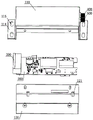
Fig. 3 is a schematic cross-sectional structure diagram of the telemetry terminal of the present invention.
Fig. 4 is a schematic view of the three-dimensional structure of the upper shell of the telemetry terminal of the present invention.
Description of reference numerals:
100. a housing; 110. an upper shell; 111. a first mounting port; 112. a fixed part; 113. a limiting notch; 114. an installation table; 115. mounting holes; 116. a second mounting opening; 120. a lower case; 121. mounting a column; 200. a circuit board; 300. an RS485 interface; 400. an input interface; 500. and (6) an output interface.
Detailed Description
In order to facilitate the understanding of those skilled in the art, the present invention will be further described with reference to the following examples, which are not intended to limit the scope of the present invention.
As shown in fig. 1 to 4, a telemetry terminal includes:
the shell 100 comprises an upper shell 110 and a lower shell 120 which are detachably connected, wherein the upper shell 110 is provided with a first mounting opening 111; one side of the lower shell 120 close to the upper shell 110 is provided with a plurality of mounting columns 121 positioned in the mounting cavities; the upper case 110, the lower case 120, and the mounting posts 121 are made of aluminum material;
the circuit board 200 is fixedly mounted on the mounting column 121, and gaps are respectively arranged between the upper surface and the lower surface of the circuit board 200 and between the upper shell 110 and the lower shell 120; and
RS485 interface 300, RS485 interface 300 locates first installing port 111, just the one end of RS485 interface 300 with circuit board 200 electricity is connected, RS485 interface 300 is located the outside of first installing port 111.
Specifically, a plurality of electrical components are welded on the circuit board 200, the RS485 interface 300 is a high-speed communication interface for receiving image data shot by the camera device, and meanwhile, the RS485 interface 300 is a high-speed communication interface, so that the practical use efficiency is high and the generated heat is large; therefore, in the practical application of this application, because circuit board 200 is installed on erection column 121, make the upper and lower two sides of circuit board 200 form the interval with epitheca 110 and inferior valve 120 respectively, thereby form the heat dissipation passageway, make things convenient for the inside air current to circulate, epitheca 110, inferior valve 120, erection column 121 all adopt aluminium material to make simultaneously, possess good heat dispersion, so as to take away the heat on the heat dissipation passageway fast, thereby reach the radiating purpose to the telemetering measurement terminating machine, heat dispersion is strong, the sealing performance of casing 100 has also been guaranteed simultaneously, thereby guarantee the waterproof dustproof effect of circuit board 200.
In this embodiment, the upper case 110 has fixing portions 112, and the fixing portions 112 extend along the direction of the upper case 110 toward the lower case 120; the lower case 120 is detachably coupled to the fixing portion 112.
Specifically, the fixing portion 112 is configured to be detachably connected to the lower shell 120, wherein the detachable connection between the lower shell 120 and the fixing portion 112 may be a screw connection, a snap connection, a plug connection, and the like, and is not limited herein.
Preferably, the detachable connection between the lower case 120 and the fixing portion 112 is a screw connection, wherein the fixing portion 112 is provided with a threaded hole or a through hole, the lower case 120 is provided with a threaded hole or a through hole corresponding to the hole of the fixing portion 112, the detachable connection between the fixing portion 112 and the lower case 120 can be realized by screws, the operation is simple and reliable, and the fixing stability is strong.
In this embodiment, the lower shell 120 is U-shaped; the number of the fixing portions 112 is two, and the two fixing portions 112 are detachably connected to both sides of the lower case 120, respectively. Therefore, after the lower shell 120 is detachably connected with the fixing part 112, the connection stability of the lower shell 120 and the upper shell 110 can be effectively ensured, and the sealing effect inside the casing 100 can be ensured.
In this embodiment, the fixing portion 112 is provided with a limiting notch 113 for limiting the installation position of the lower shell 120.
When the lower case 120 is connected to the fixing portion 112, the side of the lower case 120 contacts the side of the limiting notch 113 first, and after moving a certain distance along the side of the limiting notch 113, the upper end of the side of the lower case 120 abuts against the side of the limiting notch 113 far away from the lower case 120, so that the mounting position of the lower case 120 is limited, and the accuracy of the mounting position of the lower case 120 is ensured.
In this embodiment, the outer side of the upper casing 110 has a mounting table 114, and the mounting table 114 has a mounting hole 115.
Specifically, the mounting table 114 is integrally formed with the upper shell 110, and the mounting table 114 and the side surface of the upper shell 110 are integrally formed in an "L" shape, so that the mounting table 114 is horizontally arranged, the telemetry terminal is conveniently mounted on a surface to be mounted, and the mounting convenience is improved; in addition, at least one mounting hole 115 is formed on the mounting table 114 for fixing the mounting table 114 to the surface to be mounted, such as by screws passing through the mounting hole 115.
In this embodiment, the mounting hole 115 is an oblong hole.
Specifically, the slotted hole can be adapted to various installation scenes, namely, a certain amount of deviation can be made on the actual installation position of the remote measuring terminal according to the actual installation position, so that the installation convenience is improved, and the practicability is high.
In this embodiment, the present invention further includes an input interface 400 and an output interface 500; the upper case 110 has a second mounting port 116; one end of the input interface 400 and one end of the output interface 500 are electrically connected to the circuit board 200, and the other end of the input interface 400 and the other end of the output interface 500 are disposed outside the second mounting hole 116. The input interface 400 and the output interface 500 are disposed outside the second mounting port 116, which facilitates connection of external devices to the telemetry terminal to modify data of the control unit (e.g., chip, single chip, PLC, etc.) on the circuit board 200.
In the description of the present invention, it should be noted that, for the terms of orientation, such as "central", "transverse (X)", "longitudinal (Y)", "vertical (Z)", "length", "width", "thickness", "upper", "lower", "front", "rear", "left", "right", "vertical", "horizontal", "top", "bottom", "inner", "outer", "clockwise", "counterclockwise" and the like, the directions and positional relationships are indicated based on the directions or positional relationships shown in the drawings, and the description is merely for convenience of describing the present invention and simplifying the description, but not for indicating or implying that the device or element referred to must have a specific direction, be constructed and operated in a specific direction, and should not be construed as limiting the scope of the present invention in particular.
Furthermore, if the terms "first" and "second" are used for descriptive purposes only, they are not to be construed as indicating or implying relative importance or implicitly indicating the number of technical features. Thus, the definition of "a first" or "a second" feature may explicitly or implicitly include one or more of the features, and in the description of the invention, "a plurality" means two or more unless specifically defined otherwise.
In the present invention, unless otherwise expressly specified or limited, the terms "assembled", "connected", and "connected", if any, are to be construed broadly, e.g., as meaning fixedly connected, detachably connected, or integrally connected; or may be a mechanical connection; the two elements can be directly connected with each other or connected with each other through an intermediate medium, and the two elements can be communicated with each other. The specific meaning of the above terms in the present invention can be understood by those of ordinary skill in the art according to specific situations.
The above-mentioned embodiments only express a plurality of embodiments of the present invention, and the description thereof is specific and detailed, but not construed as limiting the scope of the present invention. It should be noted that, for those skilled in the art, without departing from the spirit of the present invention, several variations and modifications can be made, which are within the scope of the present invention. Therefore, the protection scope of the present invention should be subject to the appended claims.
Claims (7)
1. A telemetry terminal, comprising: the method comprises the following steps:
the shell comprises a detachable upper shell and a detachable lower shell, and the upper shell is provided with a first mounting port; one surface of the lower shell, which is close to the upper shell, is provided with a plurality of mounting columns positioned in the mounting cavity; the upper shell, the lower shell and the mounting column are all made of aluminum materials;
the circuit board is fixedly arranged on the mounting column, and intervals are respectively arranged between the upper surface and the lower surface of the circuit board and between the upper shell and the lower shell; and
the RS485 interface, the RS485 interface is located first installing port, just the one end of RS485 interface with the circuit board electricity is connected, the RS485 interface is located the outside of first installing port.
2. The telemetry terminal of claim 1, wherein: the upper shell is provided with fixing parts which extend along the direction of the upper shell towards the lower shell; the lower shell is detachably connected with the fixing part.
3. The telemetry terminal of claim 2, wherein: the lower shell is U-shaped; the quantity of fixed part is two, these two the fixed part respectively with the both sides of inferior valve can be dismantled and be connected.
4. The telemetry terminal of claim 2, wherein: the fixing part is provided with a limiting notch for limiting the installation position of the lower shell.
5. The telemetry terminal of claim 1, wherein: the outer side of the upper shell is provided with a mounting table, and the mounting table is provided with a mounting hole.
6. The telemetry terminal of claim 5, wherein: the mounting hole is a long round hole.
7. The telemetry terminal of claim 1, wherein: the device also comprises an input interface and an output interface; the upper shell is provided with a second mounting port; one end of the input interface and one end of the output interface are electrically connected with the circuit board, and the other end of the input interface and the other end of the output interface are arranged on the outer side of the second mounting port.
Priority Applications (1)
| Application Number | Priority Date | Filing Date | Title |
|---|---|---|---|
| CN202220701161.3U CN217331199U (en) | 2022-03-29 | 2022-03-29 | Remote measuring terminal |
Applications Claiming Priority (1)
| Application Number | Priority Date | Filing Date | Title |
|---|---|---|---|
| CN202220701161.3U CN217331199U (en) | 2022-03-29 | 2022-03-29 | Remote measuring terminal |
Publications (1)
| Publication Number | Publication Date |
|---|---|
| CN217331199U true CN217331199U (en) | 2022-08-30 |
Family
ID=83002480
Family Applications (1)
| Application Number | Title | Priority Date | Filing Date |
|---|---|---|---|
| CN202220701161.3U Active CN217331199U (en) | 2022-03-29 | 2022-03-29 | Remote measuring terminal |
Country Status (1)
| Country | Link |
|---|---|
| CN (1) | CN217331199U (en) |
-
2022
- 2022-03-29 CN CN202220701161.3U patent/CN217331199U/en active Active
Similar Documents
| Publication | Publication Date | Title |
|---|---|---|
| CN204929513U (en) | Hand -held device and use handheld cloud platform of this hand -held device | |
| CN217331199U (en) | Remote measuring terminal | |
| CN204885539U (en) | Connector socket, connector component , battery busbar subassembly and battery device | |
| CN214756935U (en) | Intelligent control power-saving terminal of 5G base station based on Internet of things technology and embedded application technology | |
| CN212851558U (en) | Radio frequency sensor chip mounting, fixing and protecting device | |
| CN110635262A (en) | Overtemperature feedback type transformer wire clamp and transformer wire clamp assembling method | |
| CN215982924U (en) | Automatically controlled box, outer machine of air conditioner and air conditioner | |
| CN212876035U (en) | Nuclear instrument control state management data transmission system | |
| CN115077734A (en) | Thermocouple mounting structure | |
| CN210571056U (en) | Watchband type wireless temperature measurement sensor based on CT power taking | |
| CN112816750A (en) | Electric energy meter with improve electric energy meter self-heating and to mutual-inductor performance influence | |
| CN214100156U (en) | Electric power terminal | |
| CN212963484U (en) | Nuclear instrument control internal environment monitoring module | |
| CN212183959U (en) | High-voltage measurement and control device for distribution and transformation line | |
| CN215268175U (en) | Junction box and photovoltaic module | |
| CN110491304A (en) | Socket and display screen | |
| CN220510217U (en) | Battery cell bracket assembly and energy storage equipment | |
| CN211352943U (en) | Heat dissipation structure of electric energy meter | |
| CN210293263U (en) | AGV sensor | |
| CN215641843U (en) | Novel GPS locator for communication engineering | |
| CN220324730U (en) | Power plug frame | |
| CN217468294U (en) | Light guide structure of low-voltage switch | |
| CN219247880U (en) | Access switch for wind power control system | |
| CN219779226U (en) | Outlet structure of controller | |
| CN216313632U (en) | Control box that protectiveness is good |
Legal Events
| Date | Code | Title | Description |
|---|---|---|---|
| GR01 | Patent grant | ||
| GR01 | Patent grant |