CN217325537U - Building foundation static load test detection device - Google Patents
Building foundation static load test detection device Download PDFInfo
- Publication number
- CN217325537U CN217325537U CN202221186640.2U CN202221186640U CN217325537U CN 217325537 U CN217325537 U CN 217325537U CN 202221186640 U CN202221186640 U CN 202221186640U CN 217325537 U CN217325537 U CN 217325537U
- Authority
- CN
- China
- Prior art keywords
- static load
- detection device
- load test
- support
- building foundation
- Prior art date
- Legal status (The legal status is an assumption and is not a legal conclusion. Google has not performed a legal analysis and makes no representation as to the accuracy of the status listed.)
- Expired - Fee Related
Links
Images


Landscapes
- Force Measurement Appropriate To Specific Purposes (AREA)
- Investigating Strength Of Materials By Application Of Mechanical Stress (AREA)
Abstract
本实用新型公开了一种建筑地基静载荷试验检测装置,包括支架,所述支架上设置支腿,所述支腿上设置有滚轮,所述滚轮下侧设置有导轨,所述支架的内侧设置有液压缸,所述液压缸竖直向下设置,所述液压缸的输出轴上设置有顶板,所述顶板下侧设置有支撑柱,所述支撑柱上插接有横板,所述横板的两端设置有固定架,所述固定架上设置有百分表,所述百分表的探头与横板相接触。通过设置导轨和滚轮,使本装置便于移动,能够快速地对地基不同位置进行静载荷的检测实验,检测效率较高,降低了作业人员的工作量。

The utility model discloses a static load test and detection device for building foundations, which comprises a bracket, a support leg is arranged on the bracket, a roller is arranged on the support leg, a guide rail is arranged on the lower side of the roller, and an inner side of the bracket is arranged There is a hydraulic cylinder, the hydraulic cylinder is arranged vertically downward, a top plate is arranged on the output shaft of the hydraulic cylinder, a support column is arranged on the lower side of the top plate, and a horizontal plate is inserted on the support column, and the horizontal plate is inserted into the support column. The two ends of the plate are provided with fixing frames, the fixing frames are provided with dial indicators, and the probes of the dial indicators are in contact with the horizontal plate. By arranging guide rails and rollers, the device is easy to move, and can quickly perform static load detection experiments on different positions of the foundation, with high detection efficiency and reduced workload of operators.
Description
技术领域technical field
本实用新型属于建筑检测设备技术领域,尤其涉及一种建筑地基静载荷试验检测装置。The utility model belongs to the technical field of building detection equipment, in particular to a static load test detection device for building foundations.
背景技术Background technique
建筑地基静载荷检测试验是运用在工程上对地基承载力检测的一项技术。在确定地基极限承载力方面,是较为准确、可靠的检验方法,作为判定某种动载检验方法是否成熟,均以静载试验成果的对比误差大小为依据。The static load detection test of building foundation is a technique used in engineering to detect the bearing capacity of foundation. In determining the ultimate bearing capacity of the foundation, it is a relatively accurate and reliable inspection method. As a judgment of whether a certain dynamic load inspection method is mature, it is based on the comparison error of the static load test results.
目前,地基静载荷检测试验通过在地基上施加一定的应力,然后通过百分表测量检测地基在受力时发生的沉降量,通过沉降量和施加的应力之间的关系进一步判断地基的静载荷。现有的建筑地基静载荷检测过程中,其检测设备占地面积较大,不便于移动,而在建筑地基静载荷检测中需要对多个点位进行检测,因此,增加了作业人员的检测负担。At present, the foundation static load detection test is to apply a certain stress on the foundation, and then measure and detect the settlement of the foundation when the foundation is under stress by means of a dial indicator, and further judge the static load of the foundation through the relationship between the settlement and the applied stress. . In the existing static load detection process of building foundations, the detection equipment covers a large area and is inconvenient to move. In the static load detection of building foundations, multiple points need to be detected, thus increasing the detection burden of operators. .
实用新型内容Utility model content
针对现有技术不足,本实用新型的目的在于提供一种建筑地基静载荷试验检测装置,解决现有技术中存在的问题。Aiming at the deficiencies of the prior art, the purpose of the utility model is to provide a static load test and detection device for building foundations, which solves the problems existing in the prior art.
本实用新型提供如下技术方案:The utility model provides the following technical solutions:
一种建筑地基静载荷试验检测装置,包括支架,所述支架上设置支腿,所述支腿上设置有滚轮,所述滚轮下侧设置有导轨,所述支架的内侧设置有液压缸,所述液压缸竖直向下设置,所述液压缸的输出轴上设置有顶板,所述顶板下侧设置有支撑柱,所述支撑柱上插接有横板,所述横板的两端设置有固定架,所述固定架上设置有百分表,所述百分表的探头与横板相接触。A static load test and detection device for building foundations, comprising a bracket, a support leg is arranged on the bracket, a roller is arranged on the support leg, a guide rail is arranged on the lower side of the roller, and a hydraulic cylinder is arranged on the inner side of the bracket, so The hydraulic cylinder is arranged vertically downward, the output shaft of the hydraulic cylinder is provided with a top plate, the lower side of the top plate is provided with a support column, the support column is inserted with a transverse plate, and both ends of the transverse plate are provided with There is a fixing frame, a dial indicator is arranged on the fixing frame, and the probe of the dial indicator is in contact with the horizontal plate.
优选的,所述支架包括支撑座,所述支撑座内设置有液压泵和液压油箱,所述液压泵、液压油箱通过相应的液压管道与液压缸连接。Preferably, the bracket includes a support seat, and a hydraulic pump and a hydraulic oil tank are arranged in the support seat, and the hydraulic pump and the hydraulic oil tank are connected with the hydraulic cylinder through corresponding hydraulic pipes.
优选的,所述顶板的内侧设置有压力传感器,所述压力传感器连接有处理器,所述压力传感器用于测量顶板对支撑柱的压应力。Preferably, a pressure sensor is provided on the inner side of the top plate, the pressure sensor is connected with a processor, and the pressure sensor is used for measuring the compressive stress of the top plate on the support column.
优选的,所述支撑座的中心位置设置有固定槽,所述固定槽内设置有配重块,所述配重块插接在固定槽内。Preferably, a fixing groove is provided at the center of the support base, a counterweight block is arranged in the fixing groove, and the counterweight block is inserted into the fixing groove.
优选的,所述配重块的表面设置有把手,所述配重块的一端设置有固定柱,另一端设置有固定槽,所述固定槽与固定柱相适配,多个所述配重块之间能够插接连接。Preferably, the surface of the counterweight block is provided with a handle, one end of the counterweight block is provided with a fixing column, and the other end is provided with a fixing groove, the fixing groove is adapted to the fixing column, and a plurality of the counterweights are provided with a handle. The blocks can be plugged in connection.
优选的,所述支撑柱上设置有通孔,所述横板插接在通孔内,所述横板呈长方体结构状。Preferably, the support column is provided with a through hole, the horizontal plate is inserted into the through hole, and the horizontal plate is in the shape of a rectangular parallelepiped.
优选的,所述固定架包括底座,所述底座上设置有立柱,所述立柱上设置有滑块,所述滑块上设置有锁紧螺栓,所述锁紧螺栓用于固定滑块。Preferably, the fixing frame includes a base, a column is provided on the base, a sliding block is provided on the column, and a locking bolt is provided on the sliding block, and the locking bolt is used for fixing the sliding block.
优选的,所述支撑柱的表面设置有第二锁紧螺栓,所述第二锁紧螺栓能够与横板接触。Preferably, the surface of the support column is provided with a second locking bolt, and the second locking bolt can be in contact with the transverse plate.
与现有技术相比,本实用新型具有以下有益效果:Compared with the prior art, the utility model has the following beneficial effects:
(1)本实用新型一种建筑地基静载荷试验检测装置,通过设置液压缸,液压缸对支撑柱施加一个作用力,支撑柱对地面就有一个作用力,地面在支撑柱的作用下产生形变,向下沉降,同时,支撑柱带动横板向下移动,横板作用于百分表,通过百分表的度数进一步计算地基的静载荷。(1) The utility model is a static load test device for building foundations. By setting a hydraulic cylinder, the hydraulic cylinder exerts a force on the support column, and the support column has a force on the ground, and the ground is deformed under the action of the support column. , settle down, at the same time, the support column drives the horizontal plate to move down, the horizontal plate acts on the dial indicator, and the static load of the foundation is further calculated by the degree of the dial indicator.
(2)本实用新型一种建筑地基静载荷试验检测装置,通过设置导轨和滚轮,支架能够在导轨上移动,能够快速地对地基不同位置进行静载荷的检测实验,检测效率较高,降低了作业人员的工作量。(2) The utility model is a static load test and detection device for building foundations. By setting guide rails and rollers, the bracket can move on the guide rails, and can quickly perform static load detection experiments on different positions of the foundation. Workload of workers.
(3)本实用新型一种建筑地基静载荷试验检测装置,通过设置配重块,能够调支架的重量,进一步调节液压缸对支撑柱的作用力,适用于不同建筑地基检测的需要,调节过程比较便捷。(3) The utility model is a construction foundation static load test detection device. By setting the counterweight block, the weight of the bracket can be adjusted, and the force of the hydraulic cylinder on the support column can be further adjusted, which is suitable for the needs of different construction foundation detection. The adjustment process more convenient.
(4)本实用新型一种建筑地基静载荷试验检测装置,通过设置两个百分表采集数据,能够有效地降低数据的误差,增加了检测精度。(4) The utility model is a static load test detection device for building foundations. By setting two dial indicators to collect data, the error of the data can be effectively reduced, and the detection accuracy can be increased.
附图说明Description of drawings
为了更清楚地说明本实用新型实施方式的技术方案,下面将对实施方式中所需要使用的附图作简单地介绍,应当理解,以下附图仅示出了本实用新型的某些实施例,因此不应被看作是对范围的限定,对于本领域普通技术人员来讲,在不付出创造性劳动的前提下,还可以根据这些附图获得其他相关的附图。In order to illustrate the technical solutions of the embodiments of the present invention more clearly, the accompanying drawings required in the embodiments will be briefly introduced below. It should be understood that the following drawings only show some embodiments of the present invention. Therefore, it should not be regarded as a limitation of the scope. For those of ordinary skill in the art, other related drawings can also be obtained from these drawings without any creative effort.
图1是本实用新型的整体结构示意图。Figure 1 is a schematic diagram of the overall structure of the present invention.
图2是本实用新型的图1左视图。Fig. 2 is the left side view of Fig. 1 of the present invention.
图3是本实用新型配重块示意图。FIG. 3 is a schematic diagram of a counterweight block of the present invention.
图4是本实用新型支撑座俯视图。FIG. 4 is a top view of the support seat of the present invention.
图5是本实用新型固定架结构示意图。FIG. 5 is a schematic diagram of the structure of the fixing frame of the present invention.
图中:1、导轨;2、固定架;3、百分表;4、支腿;5、液压泵;6、配重块;7、液压油箱;8、支架;9、液压缸;10、压力传感器;11、支撑柱;12、滚轮;13、横板;14、把手;15、固定柱;16、固定槽;17、顶板;18、支撑座;19、底座;20、立柱;21、滑块;22、锁紧螺栓。In the picture: 1. Guide rail; 2. Fixed frame; 3. Dial indicator; 4. Outrigger; 5. Hydraulic pump; 6. Counterweight; 7. Hydraulic oil tank; 8. Bracket; 9. Hydraulic cylinder; 10. Pressure sensor; 11, support column; 12, roller; 13, horizontal plate; 14, handle; 15, fixed column; 16, fixed groove; 17, top plate; 18, support seat; 19, base; 20, column; 21, Slider; 22. Locking bolts.
具体实施方式Detailed ways
为使本实用新型实施方式的目的、技术方案和优点更加清楚,下面将结合本实用新型实施方式中的附图,对本实用新型实施方式中的技术方案进行清楚、完整地描述。显然,所描述的实施方式是本实用新型一部分实施方式,而不是全部的实施方式。基于本实用新型中的实施方式,本领域普通技术人员在没有作出创造性劳动前提下所获得的所有其他实施方式,都属于本实用新型保护的范围。In order to make the purposes, technical solutions and advantages of the embodiments of the present invention more clear, the technical solutions in the embodiments of the present invention will be clearly and completely described below with reference to the accompanying drawings in the embodiments of the present invention. Obviously, the described embodiments are some, but not all, embodiments of the present invention. Based on the embodiments of the present invention, all other embodiments obtained by those of ordinary skill in the art without creative work fall within the protection scope of the present invention.
因此,以下对在附图中提供的本实用新型的实施方式的详细描述并非旨在限制要求保护的本实用新型的范围,而是仅仅表示本实用新型的选定实施方式。基于本实用新型中的实施方式,本领域普通技术人员在没有作出创造性劳动前提下所获得的所有其他实施方式,都属于本实用新型保护的范围。Accordingly, the following detailed description of the embodiments of the invention provided in the accompanying drawings is not intended to limit the scope of the invention as claimed, but is merely representative of selected embodiments of the invention. Based on the embodiments of the present invention, all other embodiments obtained by those of ordinary skill in the art without creative work fall within the protection scope of the present invention.
实施例一Example 1
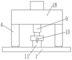
如图1-5所示,一种建筑地基静载荷试验检测装置,包括支架8,所述支架8上设置支腿4,所述支腿4上设置有滚轮12,所述滚轮12下侧设置有导轨1,所述导轨1对支架8起到了支撑的作用,所述支架8的内侧设置有液压缸9,所述液压缸9竖直向下设置,所述液压缸9的输出轴上设置有顶板17,所述顶板17下侧设置有支撑柱11,所述支撑柱11上插接有横板13,所述横板13的两端设置有固定架2,所述固定架2上设置有百分表3,所述百分表3的探头与横板13相接触,所述百分表用于测量地基的形变量。As shown in Figures 1-5, a static load test and detection device for building foundations includes a bracket 8, on which a support leg 4 is arranged, and a
所述支架8包括支撑座18,所述支撑座18内设置有液压泵5和液压油箱7,所述液压泵5、液压油箱7通过相应的液压管道、阀门与液压缸9连接,其具体连接方式为现有技术,此处对于管路的连接方式不再赘述,所述液压泵5向液压缸提供液压油。所述顶板17的内侧设置有压力传感器10,所述压力传感器连接有处理器,所述处理器用于处理压力传感器测量的数据,所述压力传感器10用于测量顶板17对支撑柱11的压应力。通过压力传感器10测量的压应力和百分表测量的形变量计算建筑地基的静载荷。The bracket 8 includes a
实施例二
如图1-5所示,一种建筑地基静载荷试验检测装置,包括支架8,所述支架8上设置支腿4,所述支腿4上设置有滚轮12,所述滚轮12下侧设置有导轨1,所述导轨1对支架8起到了支撑的作用,所述支架8的内侧设置有液压缸9,所述液压缸9竖直向下设置,所述液压缸9的输出轴上设置有顶板17,所述顶板17下侧设置有支撑柱11,所述支撑柱11上插接有横板13,所述横板13的两端设置有固定架2,所述固定架2上设置有百分表3,所述百分表3的探头与横板13相接触,所述百分表用于测量地基的形变量。As shown in Figures 1-5, a static load test and detection device for building foundations includes a bracket 8, on which a support leg 4 is arranged, and a
所述支架8包括支撑座18,所述支撑座18内设置有液压泵5和液压油箱7,所述液压泵5、液压油箱7通过相应的液压管道、阀门与液压缸9连接,其具体连接方式为现有技术,此处对于管路的连接方式不再赘述,所述液压泵5向液压缸提供液压油。所述顶板17的内侧设置有压力传感器10,所述压力传感器连接有处理器,所述处理器用于处理压力传感器测量的数据,所述压力传感器10用于测量顶板17对支撑柱11的压应力。通过压力传感器10测量的压应力和百分表测量的形变量计算建筑地基的静载荷。The bracket 8 includes a
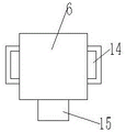
所述支撑座18的中心位置设置有固定槽16,所述固定槽16内设置有配重块6,所述配重块6插接在固定槽16内,根据实际需要调节配重块的数量,进一步调节支架8的整体质量,能够改变液压缸对支撑柱的最大作用力,适用于检测不同硬度的地基。The center position of the
所述配重块6的表面设置有把手14,所述配重块6的一端设置有固定柱15,另一端设置有固定槽16,所述固定槽16与固定柱15相适配。 所述支撑柱11上设置有通孔,所述横板13插接在通孔内,所述横板13呈长方体结构状。所述固定架2包括底座19,所述底座19上设置有立柱20,所述立柱20上设置有滑块21,所述滑块21上设置有锁紧螺栓22,所述锁紧螺栓22用于固定滑块21。所述支撑柱11的表面设置有第二锁紧螺栓,所述第二锁紧螺栓能够与横板13接触。所述第二锁紧螺栓用于固定横板13。The surface of the
通过上述技术方案得到的装置是一种建筑地基静载荷试验检测装置,在使用过程中,启动液压泵5,液压缸的轴伸出,对支撑柱11具有一个压力,根据力的传递,支撑柱11对地基具有一个向下的作用力,地基发生沉降,支撑柱11向下移动,同时,横板13向下移动并压缩百分表,此时,根据压力传感器与百分表的读数计算建筑地基的静载荷,根据力的相互作用,在液压缸顶起支架8时,支架8对轨道的作用力减小,轨道及附近区域的地基形变量较小,可以忽略不计,因此,通过本装置测量的数据误差较小,当需要更换测量地点时,移动本装置至相应的测量点即可,由于本装置设置有滚轮和轨道,便于对装置进行移动,移动过程比较便捷。The device obtained by the above technical solution is a static load test detection device for building foundations. During use, the
以上所述仅为本实用新型的优选实施方式而已,并不用于限制本实用新型,对于本领域的技术人员来说,本实用新型可以有各种更改和变化;凡在本实用新型的精神和原则之内,所作的任何修改、等同替换、改进等,均应包含在本实用新型的保护范围之内。The above are only the preferred embodiments of the present invention, and are not intended to limit the present invention. For those skilled in the art, the present invention may have various modifications and changes; Within the principle, any modification, equivalent replacement, improvement, etc. made shall be included within the protection scope of the present invention.
Claims (7)
Priority Applications (1)
| Application Number | Priority Date | Filing Date | Title |
|---|---|---|---|
| CN202221186640.2U CN217325537U (en) | 2022-05-18 | 2022-05-18 | Building foundation static load test detection device |
Applications Claiming Priority (1)
| Application Number | Priority Date | Filing Date | Title |
|---|---|---|---|
| CN202221186640.2U CN217325537U (en) | 2022-05-18 | 2022-05-18 | Building foundation static load test detection device |
Publications (1)
| Publication Number | Publication Date |
|---|---|
| CN217325537U true CN217325537U (en) | 2022-08-30 |
Family
ID=82953076
Family Applications (1)
| Application Number | Title | Priority Date | Filing Date |
|---|---|---|---|
| CN202221186640.2U Expired - Fee Related CN217325537U (en) | 2022-05-18 | 2022-05-18 | Building foundation static load test detection device |
Country Status (1)
| Country | Link |
|---|---|
| CN (1) | CN217325537U (en) |
-
2022
- 2022-05-18 CN CN202221186640.2U patent/CN217325537U/en not_active Expired - Fee Related
Similar Documents
| Publication | Publication Date | Title |
|---|---|---|
| CN102645380B (en) | Structural timber bend strength tester and structural timber bend strength test method | |
| CN104567641B (en) | A kind of Short/Medium Span Bridge deflection measuring apparatus | |
| CN106836315A (en) | A kind of vertical displacement detection means | |
| CN217210824U (en) | An elevator guide rail installation accuracy detection device | |
| CN106959216B (en) | Tramcar bogie static load test device | |
| CN202649055U (en) | Wood bending strength detecting equipment for structure | |
| CN217325537U (en) | Building foundation static load test detection device | |
| CN103322877B (en) | For checking the device of galvanizing unit zinc pot roll body state | |
| CN102788548A (en) | Steel band planeness test device | |
| CN213422016U (en) | Width detection device for bridge cracks | |
| CN111257147B (en) | Subgrade Pavement Resilience Modulus Test Device and Test Method | |
| CN109443988B (en) | Testing instrument and testing method for rheological property of coarse-grained soil | |
| CN209181981U (en) | Bellows transverse stiffness test device | |
| CN218496080U (en) | Flatness detection equipment for water supply and drainage pipeline | |
| CN109916582B (en) | A kind of deflection automatic measuring device and measuring method | |
| CN205301106U (en) | Test instrument is compared to indoor bearing weight of | |
| CN201155962Y (en) | Off-grade metal pipes detection device | |
| CN206496710U (en) | An anchor bolt anti-pullout force displacement test device | |
| CN106643634A (en) | Device for measuring water area-crossing bridge deflection and measurement method thereof | |
| CN207066853U (en) | A kind of precast concrete test device for multifunctional | |
| CN208012953U (en) | A kind of gate-type scaffold element mechanics detection device | |
| CN202099819U (en) | Treatment device of vertical static load test pile head | |
| CN217325536U (en) | Building foundation static load test device | |
| CN107132125B (en) | Slope road surface load tester | |
| CN214668179U (en) | An intelligent measurement and fast clamping test bench |
Legal Events
| Date | Code | Title | Description |
|---|---|---|---|
| GR01 | Patent grant | ||
| GR01 | Patent grant | ||
| CF01 | Termination of patent right due to non-payment of annual fee | ||
| CF01 | Termination of patent right due to non-payment of annual fee |
Granted publication date: 20220830 |