CN217316192U - Sawing machine for cutting metal raw materials - Google Patents
Sawing machine for cutting metal raw materials Download PDFInfo
- Publication number
- CN217316192U CN217316192U CN202220160966.1U CN202220160966U CN217316192U CN 217316192 U CN217316192 U CN 217316192U CN 202220160966 U CN202220160966 U CN 202220160966U CN 217316192 U CN217316192 U CN 217316192U
- Authority
- CN
- China
- Prior art keywords
- metal raw
- moving
- cutting
- sawing machine
- workbench
- Prior art date
- Legal status (The legal status is an assumption and is not a legal conclusion. Google has not performed a legal analysis and makes no representation as to the accuracy of the status listed.)
- Active
Links
Images


Abstract
The utility model belongs to the technical field of the saw cutting machine, especially, a saw cutting machine is used in cutting of metal raw and other materials, including workstation and the saw blade of installing in its top middle part, workstation top front and back end all is equipped with places the platform, place the bench and be connected with the mounting bracket, the mounting bracket is installed from outside to interior in proper order and is held component one and holding component two, holding component one is used for centre gripping plane type metal raw and other materials, holding component two is used for centre gripping arc type metal raw and other materials, be equipped with the moving member between two places the platform and the workstation, the moving member is used for adjusting the distance between two places the platform, holding component one includes electric putter one, top board, electric putter two and side guide, electric putter one is installed in mounting bracket top middle part, the top board is located the inside upper end of mounting bracket; the utility model discloses it is better to carry out spacing effect to the metal raw and other materials, can carry on spacingly to the metal raw and other materials of different shapes, and the practicality is higher.
Description
Technical Field
The utility model belongs to the technical field of the saw cuts the machine of cutting technique and specifically relates to a cutting machine is used in cutting of metal raw and other materials is related to.
Background
The sawing machine is a machine for cutting, different sawing machines can saw different materials, metal raw materials also need to be used in the process of processing production, the existing sawing machine for cutting metal raw materials is generally used for limiting the metal raw materials in a single direction, the limiting effect is weaker, the metal raw materials have different shapes, and the existing sawing machine for cutting metal raw materials is difficult to clamp the metal raw materials in different shapes, so that the existing sawing machine for cutting metal raw materials is inconvenient and affects the practicability of the existing sawing machine.
SUMMERY OF THE UTILITY MODEL
The utility model aims at the problem that above-mentioned exists with not enough, provide a sawing machine is used in cutting of metal raw and other materials, it is better to carry out spacing effect to metal raw and other materials, can carry on spacingly to the metal raw and other materials of different shapes, and the practicality is higher.
A sawing machine for cutting metal raw materials comprises a workbench and a saw blade arranged in the middle of the upper part of the workbench;
the front end and the rear end above the workbench are respectively provided with a placing table, an installing frame is connected onto the placing tables, a first clamping member and a second clamping member are sequentially installed on the installing frame from outside to inside, the first clamping member is used for clamping plane metal raw materials, and the second clamping member is used for clamping arc metal raw materials;
and a moving component is arranged between the two placing tables and the workbench and used for adjusting the distance between the two placing tables.
Preferably, the clamping component comprises a first electric push rod, an upper pressure plate, a second electric push rod and a side pressure plate, the first electric push rod is installed in the middle of the upper portion of the installation frame, the upper pressure plate is located at the upper end inside the installation frame, and an output end of the first electric push rod penetrates through the upper end of the installation frame and is connected with the upper pressure plate.
Preferably, the lower ends of the left side and the right side of the inner wall of the mounting frame are provided with the first side grooves, the second electric push rods are provided with two side grooves which are respectively arranged at the bottoms of the first side grooves, and the two pressing plates are respectively arranged in the first side grooves and connected with the power output ends of the second electric push rods which are close to the first side grooves.
Preferably, the left side and the right side above the upper pressure plate are both connected with a first moving rod, and the upper end of the first moving rod penetrates out of the mounting frame.
Preferably, the clamping member II comprises an arc-shaped plate and an electric push rod III, side grooves II are formed in the left side and the right side of the inner wall of the mounting frame, the arc-shaped plate is provided with two side grooves, the two side grooves are embedded into the two side grooves respectively, and the electric push rod III is provided with two side grooves and is installed on the bottoms of the two side grooves respectively.
Preferably, three power take off ends of electric putter are connected with close the arc, the arc leans on the outer one side upper and lower extreme all to be connected with the carriage release lever two, the carriage release lever two leans on outer one end to run through out the mounting bracket.
Preferably, the moving component comprises a moving block, a bidirectional screw rod and a motor, the motor is mounted at the front end of the workbench, a moving groove is formed in the middle of the upper surface of the workbench, the bidirectional screw rod is rotatably connected inside the moving groove, and the front end of the bidirectional screw rod penetrates out of the workbench and is connected with a power output end of the motor.
Preferably, the two moving blocks are arranged and are respectively in threaded connection with the front end and the rear end of the outer portion of the bidirectional screw rod, and the upper ends of the moving blocks are connected with the lower portion of the placing table on the same side.
Preferably, the left end and the right end of the upper surface of the workbench are both provided with sliding grooves, and the left end and the right end of the lower surface of the placing table are both connected with sliding blocks which are adjacent to the sliding grooves in sliding connection.
The beneficial effects of the utility model are that: carry out spacing at first according to metal raw and other materials length when placing the position of platform and adjusting two, when carrying out the centre gripping to plane class metal raw and other materials, carry out the centre gripping to plane class metal raw and other materials simultaneously from the upper end with controlling the end through centre gripping framework one, carry out the centre gripping through clamping member two when carrying out the centre gripping to arc class metal raw and other materials, centre gripping is assisted through clamping member one again, it is comparatively stable when carrying out the centre gripping to metal raw and other materials, it is all comparatively convenient to carry out the centre gripping to plane class metal raw and other materials and arc class metal raw and other materials, the practicality of saw cutting machine has effectively been promoted.
Drawings
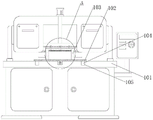
Fig. 1 is a schematic view of the overall main-view section structure of the present invention;
fig. 2 is a schematic view of a partial enlarged structure of fig. 1 according to the present invention;
FIG. 3 is a schematic front sectional view of a clamping member according to the present invention;
FIG. 4 is a schematic view of a cross-sectional structure of a second main view of the holding member of the present invention;
fig. 5 is a schematic view of the right-side sectional structure of the worktable and the mounting rack of the present invention.
The mark in the figure is: the device comprises a workbench 101, a placing table 102, a mounting frame 103, a sliding block 104, a sliding groove 105, a saw blade 106, an upper pressure plate 107, a first electric push rod 108, a first moving rod 109, a first side groove 110, a second electric push rod 111, a second side plate 112, a second side groove 113, an arc-shaped plate 114, a second moving rod 115, a third electric push rod 116, a moving groove 117, a moving block 118, a bidirectional screw rod 119 and a motor 120.
Detailed Description
As shown in fig. 1 to 5, the present application is a sawing machine for cutting metal raw materials, comprising a worktable 101 and a saw blade 106 mounted at the upper middle part of the worktable, wherein a placing table 102 is provided at each of the front and rear ends above the worktable 101, a mounting frame 103 is connected to the placing table 102, a first clamping member and a second clamping member are sequentially mounted on the mounting frame 103 from outside to inside, the first clamping member is used for clamping a plane type metal raw material, and the second clamping member is used for clamping an arc type metal raw material;
a moving component is arranged between the two placing tables 102 and the workbench 101 and used for adjusting the distance between the two placing tables 102, the moving component comprises a moving block 118, a bidirectional screw rod 119 and a motor 120, the motor 120 is installed at the front end of the workbench 101, a moving groove 117 is formed in the middle of the upper surface of the workbench 101, the bidirectional screw rod 119 is rotatably connected inside the moving groove 117, and the front end of the bidirectional screw rod 119 penetrates through the workbench 101 and is connected with the power output end of the motor 120;
the two moving blocks 118 are respectively in threaded connection with the front end and the rear end of the outer part of the bidirectional screw rod 119, the upper ends of the moving blocks 118 are connected with the lower part of the placing table 102 on the same side, the left end and the right end of the upper surface of the workbench 101 are both provided with sliding grooves 105, and the left end and the right end of the lower surface of the placing table 102 are both connected with sliding blocks 104 which are in sliding connection with the adjacent sliding grooves 105;
the motor 120 is electrified, the motor 120 drives the bidirectional screw rod 119 to rotate, the bidirectional screw rod 119 rotates to drive the moving blocks 118 on the front side and the rear side to be close to or far away from each other, the moving blocks 118 move to drive the placing tables 102 to move, the two placing tables 102 can be close to or far away from each other, the sliding blocks 104 slide along the sliding grooves 105 while the placing tables 102 move, the stability of the placing tables 102 in moving can be improved better due to the arrangement of the sliding blocks 104, a user can adjust the positions of the two placing tables 102 according to the length of metal raw materials to be cut, the front end and the rear end of the metal raw materials are located in the mounting frame 103, subsequent limiting is facilitated, the metal raw materials with different lengths can be clamped better due to the arrangement of the moving components, and convenience is achieved;
the first clamping component comprises a first electric push rod 108, an upper pressure plate 107, a second electric push rod 111 and side pressure plates 112, the first electric push rod 108 is installed in the middle of the upper portion of the installation frame 103, the upper pressure plate 107 is located at the upper end of the inside of the installation frame 103, the output end of the first electric push rod 108 penetrates out of the upper end of the installation frame 103 and is connected with the upper surface of the upper pressure plate 107, the first side grooves 110 are formed in the lower ends of the left side and the right side of the inner wall of the installation frame 103, the second electric push rod 111 is provided with two side grooves and is respectively installed at the bottoms of the two first side grooves 110, the two pressure plates 112 are respectively located inside the two first side grooves 110 and are connected with the power output ends of the second electric push rods 111, the left side and the right side above the upper pressure plate 107 are respectively connected with a first moving rod 109, and the upper end of the first moving rod 109 penetrates out of the installation frame 103;
when the metal raw material to be clamped is a plane metal raw material, the electric push rod I108 is electrified, the electric push rod I108 can drive the upper pressure plate 107 to move up and down, the electric push rod I108 drives the upper pressure plate 107 to move down to be attached to the upper surface of the metal raw material, so that the upper end of the metal raw material is limited, the moving rod I109 can move up and down along with the upper pressure plate 107 when the upper pressure plate 107 moves up and down, the moving rod I109 can prevent the left end and the right end of the upper pressure plate 107 from shifting when moving up and down to a certain extent, and the moving rod I109 can better improve the stability of the up and down movement of the upper pressure plate 107;
after the upper pressing plate 107 limits the upper end of the planar metal raw material, the electric push rod II 111 is electrified, and the electric push rod II 111 can drive the side pressing plate 112 to move inwards to clamp the left end and the right end of the planar metal raw material, so that the clamping stability of the planar metal raw material is further improved;
the second clamping component comprises arc-shaped plates 114 and electric push rods three 116, the left and right surfaces of the inner wall of the mounting frame 103 are respectively provided with two side grooves two 113, the arc-shaped plates 114 are provided with two blocks which are respectively embedded into the two side grooves two 113, the electric push rods three 116 are provided with two blocks which are respectively installed at the bottoms of the two side grooves two 113, the power output ends of the electric push rods three 116 are connected with the adjacent arc-shaped plates 114, the upper ends and the lower ends of the outer surfaces of the arc-shaped plates 114 are respectively connected with moving rods two 115, and the outer ends of the moving rods two 115 penetrate through the mounting frame 103;
when a user needs to clamp the arc-shaped metal raw material, the electric push rod III 116 is electrified, the electric push rod III 116 can drive the arc-shaped plate 114 to move inwards to clamp the arc-shaped metal raw material, the movable rod II 115 at the upper end and the lower end of the arc-shaped plate 114 can move inwards while the arc-shaped plate 114 moves inwards, and the movable rod II 115 can prevent the upper end and the lower end of the arc-shaped plate 114 from shifting when the arc-shaped plate 114 moves inwards, so that the stability of the arc-shaped plate 114 during moving is better improved;
the user can carry out further centre gripping through a pair of arc type metal raw and other materials of clamping component according to above-mentioned step to further promote the stability of arc type metal raw and other materials centre gripping, it is all comparatively convenient to carry out the centre gripping to plane type metal raw and other materials and arc type metal raw and other materials, has effectively promoted the practicality of saw cutting machine.
Claims (9)
1. A sawing machine for cutting metal raw materials comprises a workbench (101) and a saw blade (106) arranged in the middle above the workbench, and is characterized in that:
the front end and the rear end above the workbench (101) are respectively provided with a placing table (102), an installing frame (103) is connected to the placing table (102), a first clamping member and a second clamping member are sequentially installed on the installing frame (103) from outside to inside, the first clamping member is used for clamping a plane metal raw material, and the second clamping member is used for clamping an arc metal raw material;
a moving component is arranged between the two placing tables (102) and the workbench (101), and is used for adjusting the distance between the two placing tables (102).
2. The sawing machine for cutting a metallic starting material as set forth in claim 1, wherein: the first clamping component comprises a first electric push rod (108), an upper pressure plate (107), a second electric push rod (111) and a side pressure plate (112), the first electric push rod (108) is installed in the middle of the upper portion of the installation frame (103), the upper pressure plate (107) is located at the upper end of the inner portion of the installation frame (103), and the output end of the first electric push rod (108) penetrates through the upper end of the installation frame (103) and is connected with the upper pressure plate (107).
3. The sawing machine for cutting a metal raw material as defined in claim 2, wherein: side groove one (110) have all been opened to mounting bracket (103) inner wall left and right sides lower extreme, electric putter two (111) are equipped with two and install respectively in two side groove one (110) tank bottom, clamp plate (112) are equipped with two and are located two respectively inside and with close of side groove one (110) electric putter two (111) power take off end connects.
4. The sawing machine for cutting a metal raw material as defined in claim 2, wherein: the left side and the right side above the upper pressure plate (107) are both connected with a first moving rod (109), and the upper end of the first moving rod (109) penetrates through the mounting frame (103).
5. The sawing machine for cutting a metal raw material as defined in claim 1, wherein: the clamping component II comprises an arc-shaped plate (114) and an electric push rod III (116), side grooves II (113) are formed in the left side and the right side of the inner wall of the mounting frame (103), the arc-shaped plate (114) is provided with two parts and is embedded into the side grooves II (113) respectively, and the electric push rod III (116) is provided with two parts and is installed on the bottoms of the side grooves II (113) respectively.
6. The sawing machine for cutting a metal raw material as defined in claim 5, wherein: the power output end of the electric push rod III (116) is connected with the arc-shaped plate (114) in a similar mode, the upper end and the lower end of the outer side of the arc-shaped plate (114) are connected with a moving rod II (115), and the outer end of the moving rod II (115) penetrates through the mounting frame (103).
7. The sawing machine for cutting a metal raw material as defined in claim 1, wherein: the moving component comprises a moving block (118), a bidirectional screw rod (119) and a motor (120), the motor (120) is installed at the front end of the workbench (101), a moving groove (117) is formed in the middle of the upper surface of the workbench (101), the bidirectional screw rod (119) is rotatably connected to the inside of the moving groove (117), and the front end of the bidirectional screw rod (119) penetrates through the workbench (101) and is connected with the power output end of the motor (120).
8. The sawing machine for cutting a metal raw material as claimed in claim 7, wherein: the two moving blocks (118) are respectively in threaded connection with the front end and the rear end of the outer portion of the bidirectional screw rod (119), and the upper ends of the moving blocks (118) are connected with the lower portion of the placing table (102) on the same side.
9. The sawing machine for cutting a metal raw material as defined in claim 1, wherein: the left end and the right end of the upper surface of the workbench (101) are both provided with sliding grooves (105), and the left end and the right end of the lower surface of the placing platform (102) are both connected with sliding blocks (104) which are adjacent to the sliding grooves (105) in a sliding connection mode.
Priority Applications (1)
| Application Number | Priority Date | Filing Date | Title |
|---|---|---|---|
| CN202220160966.1U CN217316192U (en) | 2022-01-20 | 2022-01-20 | Sawing machine for cutting metal raw materials |
Applications Claiming Priority (1)
| Application Number | Priority Date | Filing Date | Title |
|---|---|---|---|
| CN202220160966.1U CN217316192U (en) | 2022-01-20 | 2022-01-20 | Sawing machine for cutting metal raw materials |
Publications (1)
| Publication Number | Publication Date |
|---|---|
| CN217316192U true CN217316192U (en) | 2022-08-30 |
Family
ID=82993246
Family Applications (1)
| Application Number | Title | Priority Date | Filing Date |
|---|---|---|---|
| CN202220160966.1U Active CN217316192U (en) | 2022-01-20 | 2022-01-20 | Sawing machine for cutting metal raw materials |
Country Status (1)
| Country | Link |
|---|---|
| CN (1) | CN217316192U (en) |
-
2022
- 2022-01-20 CN CN202220160966.1U patent/CN217316192U/en active Active
Similar Documents
| Publication | Publication Date | Title |
|---|---|---|
| CN218192816U (en) | Double-cutter cutting machine | |
| CN217256865U (en) | Sliding table saw with quantitative cutting function | |
| CN113084884B (en) | Cutting device is used in intention product packaging design | |
| CN217316192U (en) | Sawing machine for cutting metal raw materials | |
| CN219275985U (en) | Cutting device | |
| CN209550764U (en) | A kind of section steel cutting equipment | |
| CN212858029U (en) | Limiting and positioning fixture for gantry sawing machine for magnetic pole profiles | |
| CN212042441U (en) | Automatic cutting equipment suitable for processing industry | |
| CN210589739U (en) | Wood floor cutting machine | |
| CN217096805U (en) | Cutting device with quick clamping structure for bicycle accessory production | |
| CN210967314U (en) | Automatic cutting machine | |
| CN214108760U (en) | Automatic cutting equipment for casting pouring gate | |
| CN216031137U (en) | Cutting machine with limiting function for building material appliance | |
| CN217434550U (en) | Wood cutting device is used in cupboard production | |
| CN214819277U (en) | Cutting machine convenient for processing fixed furniture board | |
| CN212823096U (en) | Clamping piece for sawing machine | |
| CN218555714U (en) | Plate shearing machine is used in processing of aluminium veneer | |
| CN218340721U (en) | Plate slotting bending machine | |
| CN219359859U (en) | Gypsum board cutting equipment | |
| CN220162607U (en) | Copper-clad plate cutting device | |
| CN214236531U (en) | Plate cutting machine | |
| CN220533104U (en) | Metal cutting machine | |
| CN213795482U (en) | Planer material feeding unit that pay-off is steady | |
| CN218227282U (en) | Adjustable precise sliding table saw for jade bed production | |
| CN216680534U (en) | Profile sawing machine |
Legal Events
| Date | Code | Title | Description |
|---|---|---|---|
| GR01 | Patent grant | ||
| GR01 | Patent grant |