CN217237095U - Hydraulic valve detection device - Google Patents
Hydraulic valve detection device Download PDFInfo
- Publication number
- CN217237095U CN217237095U CN202221135159.0U CN202221135159U CN217237095U CN 217237095 U CN217237095 U CN 217237095U CN 202221135159 U CN202221135159 U CN 202221135159U CN 217237095 U CN217237095 U CN 217237095U
- Authority
- CN
- China
- Prior art keywords
- seat
- hydraulic valve
- sealing
- connecting rods
- workbench
- Prior art date
- Legal status (The legal status is an assumption and is not a legal conclusion. Google has not performed a legal analysis and makes no representation as to the accuracy of the status listed.)
- Active
Links
Images


Classifications
-
- Y—GENERAL TAGGING OF NEW TECHNOLOGICAL DEVELOPMENTS; GENERAL TAGGING OF CROSS-SECTIONAL TECHNOLOGIES SPANNING OVER SEVERAL SECTIONS OF THE IPC; TECHNICAL SUBJECTS COVERED BY FORMER USPC CROSS-REFERENCE ART COLLECTIONS [XRACs] AND DIGESTS
- Y02—TECHNOLOGIES OR APPLICATIONS FOR MITIGATION OR ADAPTATION AGAINST CLIMATE CHANGE
- Y02E—REDUCTION OF GREENHOUSE GAS [GHG] EMISSIONS, RELATED TO ENERGY GENERATION, TRANSMISSION OR DISTRIBUTION
- Y02E10/00—Energy generation through renewable energy sources
- Y02E10/20—Hydro energy
Abstract
The utility model discloses a hydrovalve detection device, including workstation and test integrated device, the upper end of workstation is provided with fixed adjusting device, fixed adjusting device's both sides are provided with the head rod, be provided with the second connecting rod between the head rod, be provided with test integrated device between the second connecting rod, test integrated device includes first connecting seat, high compression pump, fixed slot, sealed connector, air inlet and second connecting seat, be provided with the air inlet on the first connecting seat, first connecting seat lower extreme is provided with the fixed slot, be provided with high compression pump in the fixed slot, high compression pump's below is provided with the second connecting seat, high compression pump's lower extreme is provided with sealed connector, and such structure setting can be effectual in the original device of solution detection project single and check out test set and hydrovalve junction take place to reveal and lead to the gas tightness detection of hydrovalve to cause the problem of interference .
Description
Technical Field
The utility model belongs to the technical field of the check out test set is relevant, concretely relates to hydraulic valve detection device.
Background
The hydraulic valve is a pressure oil operated automatic element, is controlled by pressure oil of a distribution valve, is usually used in combination with an electromagnetic distribution valve, can be used for remotely controlling the on-off of oil, gas and water pipeline systems of a hydropower station, and needs to perform a series of quality detection, such as strength detection and air tightness detection, on the hydraulic valve before the hydraulic valve is put into use.
The prior hydraulic valve detection device has the following problems: 1. the existing hydraulic valve detection device cannot detect a plurality of detection items simultaneously, so that the detection time is long, the detection cost is high, and 2, when the air tightness of the hydraulic valve is detected by the existing hydraulic valve detection device, the joint of the detection device and the hydraulic valve is easy to leak, so that the accuracy of the air tightness detection result of the hydraulic valve is influenced.
Disclosure of Invention
An object of the utility model is to provide a hydraulic valve detection device to the gas tightness testing result's that the influence hydrovalve is leaked takes place to solve the problem that can not detect a plurality of projects and check out test set simultaneously and hydrovalve junction that proposes in the above-mentioned background art problem.
In order to achieve the above object, the utility model provides a following technical scheme: a hydraulic valve detection device comprises a workbench and a test integration device, wherein the upper end of the workbench is provided with a fixed adjustment device, the two sides of the fixed adjustment device and the upper end of the workbench are provided with first connecting rods, the number of the first connecting rods is four, the four first connecting rods are distributed on the workbench in two groups of symmetrical structures, the upper end of the workbench between the first connecting rods is provided with a second connecting rod, the number of the second connecting rods is two, the test integration device is arranged between the two second connecting rods and above the fixed adjustment device, the bottom of the fixed adjustment device is fixedly connected with the workbench in a screw connection mode, the right end side wall of the workbench is provided with a data transmission line, the right end of the data transmission line is provided with an operation platform, the upper end of the operation platform is provided with a data processing system, the test integration device comprises a first connecting seat, a high-pressure air pump, a fixing groove, a sealing connector, an air inlet and a second connecting seat, wherein the air inlet is formed in the middle of the upper end of the first connecting seat, the fixing groove is formed in the lower end of the first connecting seat, the high-pressure air pump is arranged at the lower end of the first connecting seat in the fixing groove, the second connecting seat is arranged below the high-pressure air pump and below the first connecting seat, and the sealing connector is arranged at the lower end of the high-pressure air pump through the second connecting seat.
Preferably, the fixing and adjusting device comprises a fixing seat, a sliding groove, a sliding block and a limiting part, the sliding groove is formed in the fixing seat, the sliding block is arranged in the sliding groove, and the limiting part is arranged at the upper end of the sliding block and the upper end of the sliding block located on the fixing seat.
Preferably, the sealing connector comprises a first sealing seat, a second sealing seat and an air duct, the second sealing seat is arranged at the tail end of the air duct, and the first sealing seat is arranged at the tail end of the second sealing seat.
Preferably, the first sealing seat comprises an outer lip seat, a groove, an inner lip seat, a connecting hole and a V-shaped spring, the inner lip seat is arranged in the middle of the outer lip seat, the connecting hole is formed in the middle of the inner lip seat, the groove is formed between the inner lip seat and the outer lip seat, and the V-shaped spring is arranged in the groove.
Preferably, the outer lip seat is of a metal material structure.
Preferably, the inner lip seat is of a rubber material structure.
Preferably, the first connecting seat and the second connecting seat are connected with the two second connecting rods in a sleeved mode.
Preferably, the two second connecting rods are in a threaded screw rod structure, and the lower ends of the two second connecting rods are arranged in the workbench and are provided with driving motor structures.
Compared with the prior art, the utility model provides a hydraulic valve detection device possesses following beneficial effect:
1. the utility model discloses in through first connecting seat, high compression pump, fixed slot, sealing connection mouth, air inlet and the second connecting seat structure that sets up among the test integrated device, adjusting device is fixed in the cooperation, can carry out the intensity and the gas tightness detection of hydrovalve simultaneously, increases detection efficiency save time cost, improve equipment's integrated level, reduce the test cost who detects the project.
2. The utility model discloses a first seal receptacle in the sealed connector structure, the second seal receptacle, outer lip seat in air duct and the first seal receptacle, a groove, interior lip seat, connecting hole and V type spring structure, can make the sealed connector carry out gas tightness with the hydrovalve and detect time measuring, increase the sealed effect of being connected of sealed connector and hydrovalve import, avoid the sealed connector to take place gas leakage with the junction of hydrovalve import, thereby the sealed problem of the junction of avoiding check out test set leads to causing the interference to the detection of the gas tightness of hydrovalve, make the gas tightness testing result of hydrovalve more accurate effective.
Drawings
The accompanying drawings are included to provide a further understanding of the invention, and are incorporated in and constitute a part of this specification, illustrate embodiments of the invention, and do not constitute a limitation on the invention, and in the drawings:
fig. 1 is a schematic view of the overall structure of a hydraulic valve detection device provided by the present invention;
FIG. 2 is a schematic structural view of a bone adjustment device of a hydraulic valve detection device according to the present invention;
fig. 3 is a schematic structural view of a testing integration device of a hydraulic valve testing device according to the present invention;
fig. 4 is a schematic view of a sealing connector structure of a hydraulic valve detection device provided by the present invention;
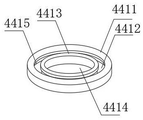
fig. 5 is a schematic structural view of a first seal seat of a hydraulic valve detection device provided by the present invention;
fig. 6 is a schematic cross-sectional structure view of a first seal seat of a hydraulic valve detection device according to the present invention;
in the figure: 1. a work table; 2. fixing the adjusting device; 3. a second connecting rod; 4. testing the integrated device; 5. a first connecting rod; 6. a data transmission line; 7. a data processing system; 8. an operation table; 21. a fixed seat; 22. a chute; 23. a slider; 24. a limiting member; 41. a first connecting seat; 42. a high pressure air pump; 43. fixing grooves; 44. sealing the connecting port; 45. an air inlet; 46. a second connecting seat; 441. a first seal seat; 442. a second seal seat; 443. an air duct; 4411. an outer lip seat; 4412. a groove; 4413. an inner lip seat; 4414. connecting holes; 4415. and a V-shaped spring.
Detailed Description
The technical solutions in the embodiments of the present invention will be described clearly and completely with reference to the accompanying drawings in the embodiments of the present invention, and it is obvious that the described embodiments are only some embodiments of the present invention, not all embodiments. Based on the embodiments in the present invention, all other embodiments obtained by a person skilled in the art without creative work belong to the protection scope of the present invention.
Example one
Referring to fig. 1 and fig. 3, the present invention provides a technical solution: a hydraulic valve detection device comprises a workbench 1 and a test integration device 4, wherein the upper end of the workbench 1 is provided with a fixed adjusting device 2, the two sides of the fixed adjusting device 2 and the upper end of the workbench 1 are provided with first connecting rods 5, the number of the first connecting rods 5 is four, the four first connecting rods 5 are distributed on the workbench 1 in two groups of symmetrical structures, the upper end of the workbench 1 between the first connecting rods 5 is provided with a second connecting rod 3, the number of the second connecting rods 3 is two, the test integration device 4 is arranged above the fixed adjusting device 2 between the two second connecting rods 3, the bottom of the fixed adjusting device 2 is fixedly connected with the workbench 1 in a screw connection mode, the side wall of the right end of the workbench 1 is provided with a data transmission line 6, the right end of the data transmission line 6 is provided with an operating platform 8, the upper end of the operating platform 8 is provided with a data processing system 7, the test integration device 4 comprises a first connecting seat 41, a high-pressure air pump 42, a fixing groove 43, a sealing connecting port 44, an air inlet 45 and a second connecting seat 46, the upper end middle part of the first connecting seat 41 is provided with the air inlet 45, the lower end of the first connecting seat 41 is provided with the fixing groove 43, the lower end in the fixing groove 43 and located in the first connecting seat 41 is provided with the high-pressure air pump 42, the lower part of the high-pressure air pump 42 and the lower part located in the first connecting seat 41 are provided with the second connecting seat 46, and the lower end of the high-pressure air pump 42 penetrates through the second connecting seat 46 and is provided with the sealing connecting port 44.
Example two
Referring to fig. 1 and 2, the present invention provides a technical solution: the utility model provides a hydraulic valve detection device, fixed adjusting device 2 includes fixing base 21, spout 22, slider 23 and locating part 24, is provided with spout 22 on the fixing base 21, is provided with slider 23 in the spout 22, and the upper end that just is located fixing base 21 of slider 23 is provided with locating part 24, sets up through above-mentioned structure, can also adjust the position of the relative test integrated device 4 of hydrovalve through fixed adjusting device 2 when fixing the hydrovalve.
EXAMPLE III
Referring to fig. 3, 4, 5 and 6, the present invention provides a technical solution: a hydraulic valve detection device is characterized in that a sealing connection port 44 comprises a first sealing seat 441, a second sealing seat 442 and an air guide pipe 443, the second sealing seat 442 is arranged at the tail end of the air guide pipe 443, the first sealing seat 441 is arranged at the tail end of the second sealing seat 442, the first sealing seat 441 comprises an outer lip seat 4411, a groove 4412, an inner lip seat 4413, a connection hole 4414 and a V-shaped spring 4415, the inner lip seat 4413 is arranged in the middle of the outer lip seat 4411, the connection hole 4414 is arranged in the middle of the inner lip seat 4413, the groove 4412 is arranged between the inner lip seat 4413 and the outer lip seat 4411, the V-shaped spring 4415 is arranged in the groove 4412, the outer lip seat 4411 is of a metal structure, the inner lip seat 4413 is of a rubber structure, and the air tightness detection result of a hydraulic valve, which is influenced by leakage at the connection position of a connection port sealing 4 and the hydraulic valve, can be avoided through the arrangement.
Example four
Referring to fig. 1, the present invention provides a technical solution: the utility model provides a hydraulic valve detection device, first connecting seat 41 and second connecting seat 46 are all connected with two second connecting rods 3 through the mode that cup joints, two second connecting rods 3 are the screw thread lead screw structure, and the lower extreme of two second connecting rods 3 just is located and is provided with the driving motor structure in the workstation 1, second connecting rod 3 through two screw thread lead screw structures of driving motor mechanism control, thereby reach the interval between control second connecting seat 46 and the first connecting seat 41, be convenient for carry out intensity to the hydrovalve and examine time measuring, from last to exerting pressure down to the hydrovalve.
The utility model discloses a theory of operation and use flow: after the utility model is installed, the driving motor inside the workbench 1 is controlled to work through the data processing system 7 on the operating platform 8, the second connecting rod 3 with a screw thread structure rotates, so that the second connecting seat 46 positioned at the lower part in the test integrated device 4 moves upwards along the two groups of first connecting rods 5 and the two second connecting rods 3, the fixed adjusting device 2 is exposed, then in the fixed adjusting device 2, the two limiting parts 24 slide in the sliding groove 22 on the fixed seat 21 through the sliding block 23 at the lower end, the distance between the two limiting parts 24 is changed, then the hydraulic valve to be tested is placed between the two limiting parts 24, then the two limiting parts 24 are reset, so that the hydraulic valve clamped in the middle is fixed, after the hydraulic valve is fixed, the driving motor in the workbench 1 receives the control instruction of the data processing system 7, and reversely drives the second connecting rod 3 to rotate, the second connecting seat 46 positioned at the lower part in the test integration device 4 is lowered, the sealing connecting port 44 is connected with the hydraulic valve, then air is extracted from the air inlet 45 by the high-pressure air pump 42 positioned in the fixing groove 43 in the first connecting seat 41 and the second connecting seat 46, the air is pressurized and then is conveyed to the hydraulic valve through the sealing connecting port 44 to carry out air tightness detection, the strength of the hydraulic valve is tested by the first connecting seat 41 and the second connecting seat 46, the tested data is guided into a data processing system through a data transmission line to be processed and analyzed in the next step, the synchronous detection of the strength and the air tightness of the hydraulic valve is completed, in the connection of the sealing connecting port 44 and the hydraulic valve, the inlet of the hydraulic valve is sleeved in the first sealing seat 441, high-pressure air is pumped into the hydraulic valve through the air guide tube 443 communicated with the second sealing seat 442 to carry out air tightness detection, in the first sealing seat 441, an inlet of the hydraulic valve penetrates through the connecting hole 4414, the inner lip seat 4413 is attached to a pipe wall of the inlet of the hydraulic valve and limited by the outer lip seat 4411 made of metal, when high-pressure gas circulates in the connecting hole 4414, the high-pressure gas applies extrusion force to the inner lip seat 4413, the inner lip seat 4413 made of rubber deforms towards the direction of the outer lip seat 4411 under the action of the extrusion force, so that the V-shaped spring 4415 embedded in the groove 4412 deforms, two ends of the V-shaped spring 4415 can be extruded, the outer lip seat 4411 is of a metal structure and is difficult to deform, the V-shaped spring 4415 can only apply tension to the inner lip seat 4413, so that the inner lip seat 4413 is tightly attached to the pipe wall of the inlet of the hydraulic valve, leakage of the high-pressure gas at the connecting part of the sealing connecting port 44 and the hydraulic valve is avoided, the gas tightness detection structure of the hydraulic valve is inaccurate, and the problems that the detection items are single in the original device and the leakage occurs at the connecting part of the hydraulic valve can be effectively solved through the structure arrangement This leads to a problem of interference with the detection of the airtightness of the hydraulic valve.
Although embodiments of the present invention have been shown and described, it will be appreciated by those skilled in the art that changes, modifications, substitutions and alterations can be made in these embodiments without departing from the principles and spirit of the invention, the scope of which is defined in the appended claims and their equivalents.
Claims (8)
1. The utility model provides a hydraulic valve detection device, includes workstation (1) and test integrated device (4), its characterized in that: the upper end of the workbench (1) is provided with a fixed adjusting device (2), two sides of the fixed adjusting device (2) and the upper end of the workbench (1) are provided with first connecting rods (5), the first connecting rods (5) are four, the first connecting rods (5) are distributed on the workbench (1) in two groups of symmetrical structures, second connecting rods (3) are arranged between the first connecting rods (5) and on the workbench (1), the second connecting rods (3) are two, a test integration device (4) is arranged between the second connecting rods (3) and above the fixed adjusting device (2), the bottom of the fixed adjusting device (2) is fixedly connected with the workbench (1) in a screw connection mode, and a data transmission line (6) is arranged on the side wall of the right end of the workbench (1), an operation table (8) is arranged at the right end of the data transmission line (6), a data processing system (7) is arranged at the upper end of the operation table (8), the test integrated device (4) comprises a first connecting seat (41), a high-pressure air pump (42), a fixing groove (43), a sealing connecting port (44), an air inlet (45) and a second connecting seat (46), the middle part of the upper end of the first connecting seat (41) is provided with an air inlet (45), the lower end of the first connecting seat (41) is provided with a fixed groove (43), the fixed groove (43) is internally provided with a high-pressure air pump (42) which is positioned at the lower end of the first connecting seat (41), a second connecting seat (46) is arranged below the high-pressure air pump (42) and below the first connecting seat (41), the lower end of the high-pressure air pump (42) penetrates through the second connecting seat (46) and is provided with a sealing connecting port (44).
2. A hydraulic valve testing apparatus according to claim 1, wherein: the fixing and adjusting device (2) comprises a fixing seat (21), a sliding groove (22), a sliding block (23) and a limiting part (24), wherein the sliding groove (22) is formed in the fixing seat (21), the sliding block (23) is arranged in the sliding groove (22), and the limiting part (24) is arranged at the upper end of the sliding block (23) and the upper end of the fixing seat (21).
3. A hydraulic valve testing apparatus according to claim 1, wherein: the sealing connection port (44) comprises a first sealing seat (441), a second sealing seat (442) and an air guide pipe (443), wherein the second sealing seat (442) is arranged at the tail end of the air guide pipe (443), and the first sealing seat (441) is arranged at the tail end of the second sealing seat (442).
4. A hydraulic valve testing apparatus according to claim 3, wherein: the first sealing seat (441) comprises an outer lip seat (4411), a groove (4412), an inner lip seat (4413), a connecting hole (4414) and a V-shaped spring (4415), wherein the inner lip seat (4413) is arranged in the middle of the outer lip seat (4411), the connecting hole (4414) is arranged in the middle of the inner lip seat (4413), the groove (4412) is arranged between the inner lip seat (4413) and the outer lip seat (4411), and the V-shaped spring (4415) is arranged in the groove (4412).
5. A hydraulic valve testing apparatus according to claim 4, wherein: the outer lip seat (4411) is of a metal material structure.
6. A hydraulic valve testing apparatus according to claim 4, wherein: the inner lip seat (4413) is of a rubber material structure.
7. A hydraulic valve testing apparatus according to claim 1, wherein: the first connecting seat (41) and the second connecting seat (46) are connected with the two second connecting rods (3) in a sleeved mode.
8. A hydraulic valve testing apparatus according to claim 1, wherein: the two second connecting rods (3) are of threaded screw rod structures, and the lower ends of the two second connecting rods (3) are located in the workbench (1) and are internally provided with driving motor structures.
Priority Applications (1)
| Application Number | Priority Date | Filing Date | Title |
|---|---|---|---|
| CN202221135159.0U CN217237095U (en) | 2022-05-12 | 2022-05-12 | Hydraulic valve detection device |
Applications Claiming Priority (1)
| Application Number | Priority Date | Filing Date | Title |
|---|---|---|---|
| CN202221135159.0U CN217237095U (en) | 2022-05-12 | 2022-05-12 | Hydraulic valve detection device |
Publications (1)
| Publication Number | Publication Date |
|---|---|
| CN217237095U true CN217237095U (en) | 2022-08-19 |
Family
ID=82824049
Family Applications (1)
| Application Number | Title | Priority Date | Filing Date |
|---|---|---|---|
| CN202221135159.0U Active CN217237095U (en) | 2022-05-12 | 2022-05-12 | Hydraulic valve detection device |
Country Status (1)
| Country | Link |
|---|---|
| CN (1) | CN217237095U (en) |
-
2022
- 2022-05-12 CN CN202221135159.0U patent/CN217237095U/en active Active
Similar Documents
| Publication | Publication Date | Title |
|---|---|---|
| CN207263385U (en) | A kind of fuel filter device for detecting sealability | |
| CN108507728B (en) | Modularized heat tracing integration station pressurizing testing device | |
| CN216559591U (en) | Be used for fire hose valve detection device | |
| CN113390586B (en) | Airtight check out test set for manometer | |
| CN217237095U (en) | Hydraulic valve detection device | |
| CN213121019U (en) | Air tightness detection device for processing of groove pipe fitting | |
| CN210375684U (en) | Valve pressing test device for welding connection | |
| CN112317361A (en) | Tap gas tightness detection device | |
| CN217687759U (en) | Valve sealing performance detection equipment | |
| CN218916699U (en) | Valve gas tightness detection device | |
| CN113952590B (en) | Catheter ventilation movement assembly | |
| CN210464806U (en) | Leakage stoppage performance test device | |
| CN115524080A (en) | Valve air tightness detection device | |
| CN208588514U (en) | A kind of core of membrane type gas meter ability of swimming leakage detection apparatus | |
| CN207335986U (en) | A kind of equipment of more bellowss airtight test at the same time | |
| CN110398318B (en) | PE steel-plastic straight pipe air tightness testing machine | |
| CN216207317U (en) | Air tightness testing device | |
| CN206754819U (en) | A kind of natural gas line pressure testing device | |
| CN112518609A (en) | Guide positioning mechanism for catheter | |
| CN202468262U (en) | Small pressure testing device | |
| CN216955019U (en) | Air tightness leak hunting machine for steel-plastic conversion | |
| CN218546043U (en) | Automatic change quick detection device | |
| CN219777009U (en) | Water meter case tightness checking device | |
| CN219224078U (en) | Automatic change valve leak hunting device | |
| CN214748700U (en) | Pressure measuring sealing device for dialyzer |
Legal Events
| Date | Code | Title | Description |
|---|---|---|---|
| GR01 | Patent grant | ||
| GR01 | Patent grant |