CN217179357U - Energy-saving environment-friendly straw biological particle combustion furnace - Google Patents
Energy-saving environment-friendly straw biological particle combustion furnace Download PDFInfo
- Publication number
- CN217179357U CN217179357U CN202220814244.3U CN202220814244U CN217179357U CN 217179357 U CN217179357 U CN 217179357U CN 202220814244 U CN202220814244 U CN 202220814244U CN 217179357 U CN217179357 U CN 217179357U
- Authority
- CN
- China
- Prior art keywords
- wall
- energy
- environment
- gas
- cooling tube
- Prior art date
- Legal status (The legal status is an assumption and is not a legal conclusion. Google has not performed a legal analysis and makes no representation as to the accuracy of the status listed.)
- Active
Links
Images

Classifications
-
- Y—GENERAL TAGGING OF NEW TECHNOLOGICAL DEVELOPMENTS; GENERAL TAGGING OF CROSS-SECTIONAL TECHNOLOGIES SPANNING OVER SEVERAL SECTIONS OF THE IPC; TECHNICAL SUBJECTS COVERED BY FORMER USPC CROSS-REFERENCE ART COLLECTIONS [XRACs] AND DIGESTS
- Y02—TECHNOLOGIES OR APPLICATIONS FOR MITIGATION OR ADAPTATION AGAINST CLIMATE CHANGE
- Y02P—CLIMATE CHANGE MITIGATION TECHNOLOGIES IN THE PRODUCTION OR PROCESSING OF GOODS
- Y02P70/00—Climate change mitigation technologies in the production process for final industrial or consumer products
- Y02P70/10—Greenhouse gas [GHG] capture, material saving, heat recovery or other energy efficient measures, e.g. motor control, characterised by manufacturing processes, e.g. for rolling metal or metal working
Landscapes
- Chimneys And Flues (AREA)
Abstract
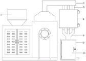
The utility model discloses an energy-concerving and environment-protective type straw bio-particle fires burning furnace relates to bio-particle and fires burning furnace technical field, now proposes following scheme, including firing burning furnace body, it is equipped with the gas collecting channel to fire burning furnace body top outer wall, and gas collecting channel top inner wall connection has the gas-supply pipe, gas-supply pipe bottom inner wall connection has the cooling tube that the equidistance distributes, and the cooling tube outer wall is fixed with the water tank, first heat-conducting plate and the second heat-conducting plate that the equidistance distributes are pegged graft respectively to cooling tube both sides outer wall, and are connected with the three-way pipe bottom the cooling tube, the three-way pipe bottom is connected with the purifying box, and the electric fan is installed to the three-way pipe inner wall. The utility model discloses can carry out the heat exchange with the water in flue gas and the water tank, realize waste heat recovery, it is more energy-conserving, flue gas after waste heat recovery blows in the purifying box through the electric fan in, through the external discharge of outlet duct again after the absorption of box with a net internal activated carbon, avoided the direct outer row of flue gas to pollute the surrounding air environment, environmental protection more.
Description
Technical Field
The utility model relates to a biological particle fires burning furnace technical field, especially relates to energy-concerving and environment-protective type straw biological particle fires burning furnace.
Background
The biomass particle combustion furnace is widely applied to various heat energy industries such as boilers, die casting machines, industrial kilns, combustion furnaces, smelting furnaces, kitchen equipment, drying equipment, food drying equipment, ironing equipment, baking finish equipment, road building mechanical equipment, industrial annealing furnaces and asphalt heating equipment, but the existing biomass particle combustion furnace does not have a waste heat recovery function during working, so that heat waste is caused, energy is not saved, simultaneously, the produced smoke is directly discharged outwards, and the environment is not protected.
SUMMERY OF THE UTILITY MODEL
The utility model aims at solving the defects existing in the prior art and providing an energy-saving and environment-friendly straw bio-particle combustion furnace.
In order to realize the purpose, the utility model adopts the following technical scheme:
energy-concerving and environment-protective type straw biological particle fires burning furnace, including firing burning furnace body, it is equipped with the gas collecting channel to fire burning furnace body top outer wall, and gas collecting channel top inner wall is connected with the gas-supply pipe, gas-supply pipe bottom inner wall is connected with the cooling tube that the equidistance distributes, and the cooling tube outer wall is fixed with the water tank, the first heat-conducting plate and the second heat-conducting plate that the equidistance distributes are pegged graft respectively to the cooling tube both sides outer wall, and the cooling tube bottom is connected with the three-way pipe, the three-way pipe bottom is connected with the purifying box, and the electric fan is installed to the three-way pipe inner wall.
Preferably, the inner wall of the purifying box is fixed with net cages which are distributed at equal intervals through bolts, and the net cages are filled with activated carbon.
Preferably, the top of the inner wall of one side of the water tank is connected with a water inlet valve, and the bottom of the inner wall of one side of the water tank is connected with a water outlet valve.
Preferably, the outer wall of one side of the purifying box is provided with a mounting opening, the inner wall of the mounting opening is hinged with a door plate, and a sealing strip is bonded at the joint of the door plate and the inner wall of the mounting opening.
Preferably, first heat-conducting plate and second heat-conducting plate distribute each other crisscross, and purifying box one side inner wall is connected with the outlet duct.
Preferably, the electric fan is connected with a switch through a wire, and the switch is connected with an external power supply through a power line.
The utility model has the advantages that:
1. the gas-collecting hood and the gas pipe can guide the flue gas into the radiating pipe to exchange heat with water in the water tank, so that waste heat recovery is realized, energy is saved, the flowing speed of the flue gas in the radiating pipe can be delayed through the first heat-conducting plate and the second heat-conducting plate, the relative contact area of the flue gas and the water is increased, and the heat exchange efficiency is further improved;
2. the flue gas after waste heat recovery blows in the purifying box through the electric fan, and is discharged outside through the outlet duct after the absorption of the active carbon in the net cage, thereby avoiding the direct discharge of the flue gas to pollute the surrounding air environment and being more environment-friendly.
Drawings
FIG. 1 is a front sectional view of an energy-saving and environment-friendly straw bio-particle combustion furnace provided by the utility model;
FIG. 2 is a front view of the energy-saving and environment-friendly straw bio-particle combustion furnace provided by the present invention;
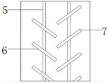
FIG. 3 is a partial enlarged view of the energy-saving and environment-friendly straw bio-particle combustion furnace provided by the utility model.
In the figure: 1. a furnace body; 2. a gas-collecting hood; 3. a gas delivery pipe; 4. a water tank; 5. a radiating pipe; 6. a first heat-conducting plate; 7. a second heat-conducting plate; 8. a three-way pipe; 9. a purification box; 10. an electric fan; 11. a net cage; 12. an air outlet pipe; 13. a water inlet valve; 14. a water outlet valve; 15. a door panel.
Detailed Description
The technical solutions in the embodiments of the present invention will be described clearly and completely with reference to the accompanying drawings in the embodiments of the present invention, and it is obvious that the described embodiments are only some embodiments of the present invention, not all embodiments.
Example 1:
referring to fig. 1-3, the energy-saving and environment-friendly straw bio-particle combustion furnace comprises a combustion furnace body 1, wherein a gas collecting hood 2 is arranged on the outer wall of the top of the combustion furnace body 1, a gas conveying pipe 3 is connected to the inner wall of the top of the gas collecting hood 2, radiating pipes 5 which are distributed equidistantly are connected to the inner wall of the bottom of the gas conveying pipe 3, a water tank 4 is fixed to the outer wall of each radiating pipe 5, smoke can be guided into the radiating pipes 5 through the arranged gas collecting hood 2 and the arranged gas conveying pipe 3, and heat exchange can be carried out with water in the water tank 4, so that waste heat recovery is realized, and energy is saved;
the top of the inner wall of one side of the water tank 4 is connected with a water inlet valve 13, the bottom of the inner wall of one side of the water tank 4 is connected with a water outlet valve 14, the outer walls of the two sides of the radiating pipe 5 are respectively inserted with a first heat conduction plate 6 and a second heat conduction plate 7 which are distributed equidistantly, the first heat conduction plate 6 and the second heat conduction plate 7 are distributed in a staggered manner, the flow speed of the flue gas in the radiating pipe 5 can be delayed through the arranged first heat conduction plate 6 and the second heat conduction plate 7, the relative contact area of the flue gas and water is increased, and the heat exchange efficiency is further improved;
and the inner wall of one side of the purifying box 9 is connected with an air outlet pipe 12, the bottom of the radiating pipe 5 is connected with a three-way pipe 8, the bottom of the three-way pipe 8 is connected with the purifying box 9, the outer wall of one side of the purifying box 9 is provided with an installation opening, the inner wall of the installation opening is hinged with a door plate 15, the joint of the inner wall of the door plate 15 and the installation opening is bonded with a sealing strip, and the inner wall of the three-way pipe 8 is provided with an electric fan 10.
Example 2:
referring to fig. 1-3, an energy-saving and environment-friendly straw bio-particle combustion furnace comprises a combustion furnace body 1, a gas collecting hood 2 is arranged on the outer wall of the top of the combustion furnace body 1, a gas pipe 3 is connected to the inner wall of the top of the gas collecting hood 2, radiating pipes 5 are connected to the inner wall of the bottom of the gas pipe 3 and are distributed equidistantly, a water tank 4 is fixed on the outer wall of the radiating pipes 5, flue gas can be guided into the radiating pipes 5 through the arranged gas collecting hood 2 and gas pipe 3 to exchange heat with water in the water tank 4, waste heat recovery is realized, energy is saved, a water inlet valve 13 is connected to the top of the inner wall on one side of the water tank 4, a water outlet valve 14 is connected to the bottom of the inner wall on one side of the water tank 4, first heat conducting plates 6 and second heat conducting plates 7 are respectively inserted and distributed equidistantly on the outer walls on both sides of the radiating pipes 5, and the first heat conducting plates 6 and the second heat conducting plates 7 are distributed in a staggered way, the flow speed of the flue gas in the radiating pipe 5 can be delayed through the arranged first heat-conducting plate 6 and the second heat-conducting plate 7, the relative contact area of the flue gas and water is increased, and the heat exchange efficiency is further improved;
an air outlet pipe 12 is connected to the inner wall of one side of the purifying box 9, the bottom of the radiating pipe 5 is connected with a three-way pipe 8, the bottom of the three-way pipe 8 is connected with the purifying box 9, net cages 11 which are distributed equidistantly are fixed to the inner wall of the purifying box 9 through bolts, activated carbon is filled in the net cages 11, flue gas after waste heat recovery is blown into the purifying box 9 through an electric fan 10, and is adsorbed by the activated carbon in the net cages 11 and then discharged outside through the air outlet pipe 12, so that the flue gas is prevented from being directly discharged outside to pollute the surrounding air environment, and the environment is more environment-friendly;
the outer wall of one side of the purifying box 9 is provided with a mounting opening, the inner wall of the mounting opening is hinged with a door plate 15, a sealing strip is bonded at the joint of the door plate 15 and the inner wall of the mounting opening, an electric fan 10 is arranged on the inner wall of the three-way pipe 8, the electric fan 10 is connected with a switch through a wire, and the switch is connected with an external power supply through a power line.
The working principle is as follows: water is filled into the water tank 4 through the water inlet valve 13, smoke generated during combustion of the combustion furnace body 1 enters the gas collecting hood 3 through the gas collecting hood 2, enters the radiating pipe 5 through the gas collecting hood 3, exchanges heat with water in the water tank 4 to realize waste heat recovery, the electric fan 10 is started, the smoke subjected to the waste heat recovery is blown into the purifying box 9 through the electric fan 10, and is exhausted outside through the air outlet pipe 12 after being adsorbed by active carbon in the net cage 11.
The above, only be the concrete implementation of the preferred embodiment of the present invention, but the protection scope of the present invention is not limited thereto, and any person skilled in the art is in the technical scope of the present invention, according to the technical solution of the present invention and the utility model, the concept of which is equivalent to replace or change, should be covered within the protection scope of the present invention.
Claims (6)
1. Energy-concerving and environment-protective type straw biological particle fires burning furnace, including firing burning furnace body (1), its characterized in that, it is equipped with gas collecting channel (2) to fire burning furnace body (1) top outer wall, and gas collecting channel (2) top inner wall is connected with gas-supply pipe (3), gas-supply pipe (3) bottom inner wall is connected with cooling tube (5) that the equidistance distributes, and cooling tube (5) outer wall is fixed with water tank (4), cooling tube (5) both sides outer wall pegs graft respectively has first heat-conducting plate (6) and second heat-conducting plate (7) that the equidistance distributes, and cooling tube (5) bottom is connected with three-way pipe (8), three-way pipe (8) bottom is connected with purifying box (9), and electric fan (10) are installed to three-way pipe (8) inner wall.
2. The energy-saving and environment-friendly straw bio-particle combustion furnace as claimed in claim 1, wherein the inner wall of the purification box (9) is fixed with net boxes (11) which are equidistantly distributed through bolts, and the net boxes (11) are filled with activated carbon.
3. The energy-saving and environment-friendly straw bio-particle combustion furnace as claimed in claim 1, wherein the top of the inner wall of one side of the water tank (4) is connected with a water inlet valve (13), and the bottom of the inner wall of one side of the water tank (4) is connected with a water outlet valve (14).
4. The energy-saving environment-friendly straw bio-particle combustion furnace as claimed in claim 1, wherein an installation opening is formed in an outer wall of one side of the purification box (9), a door plate (15) is hinged to an inner wall of the installation opening, and a sealing strip is bonded to a joint of the door plate (15) and the inner wall of the installation opening.
5. The energy-saving and environment-friendly straw bio-particle combustion furnace as claimed in claim 1, wherein the first heat conduction plate (6) and the second heat conduction plate (7) are distributed in a staggered manner, and an air outlet pipe (12) is connected to the inner wall of one side of the purification box (9).
6. The energy-saving and environment-friendly straw bio-particle combustion furnace as claimed in claim 1, wherein the electric fan (10) is connected with a switch through a wire, and the switch is connected with an external power supply through a power line.
Priority Applications (1)
| Application Number | Priority Date | Filing Date | Title |
|---|---|---|---|
| CN202220814244.3U CN217179357U (en) | 2022-04-11 | 2022-04-11 | Energy-saving environment-friendly straw biological particle combustion furnace |
Applications Claiming Priority (1)
| Application Number | Priority Date | Filing Date | Title |
|---|---|---|---|
| CN202220814244.3U CN217179357U (en) | 2022-04-11 | 2022-04-11 | Energy-saving environment-friendly straw biological particle combustion furnace |
Publications (1)
| Publication Number | Publication Date |
|---|---|
| CN217179357U true CN217179357U (en) | 2022-08-12 |
Family
ID=82708219
Family Applications (1)
| Application Number | Title | Priority Date | Filing Date |
|---|---|---|---|
| CN202220814244.3U Active CN217179357U (en) | 2022-04-11 | 2022-04-11 | Energy-saving environment-friendly straw biological particle combustion furnace |
Country Status (1)
| Country | Link |
|---|---|
| CN (1) | CN217179357U (en) |
-
2022
- 2022-04-11 CN CN202220814244.3U patent/CN217179357U/en active Active
Similar Documents
| Publication | Publication Date | Title |
|---|---|---|
| CN204830454U (en) | Many return strokes living beings hot -blast furnace | |
| CN205373043U (en) | Grain drying tower heating system's surplus heat energy -saving processing system | |
| CN202133096U (en) | Energy-saving low pressure hot water boiler | |
| CN217179357U (en) | Energy-saving environment-friendly straw biological particle combustion furnace | |
| CN101650073B (en) | Baffled hot-blast stove | |
| CN217503983U (en) | Integrated hot blast stove | |
| CN1800762A (en) | Hot-air furnace combined by combustion chamber and dustproof multi-stage heat exchanger with burning-resistant device | |
| CN212962228U (en) | Wall-mounted gas stove smoke exhaust and air exchange system and wall-mounted gas stove | |
| CN212300037U (en) | Corrugated pipe energy saver suitable for smoking furnace | |
| CN210569203U (en) | Steam hot air double-coil hot air furnace | |
| CN101021358B (en) | Energy conserving environmental protective non-pressure heating furnace | |
| CN111678340A (en) | Zinc alloy energy-saving environment-friendly gas crucible furnace | |
| CN201449007U (en) | A turn-back flow coal burning hot air furnace | |
| CN2396350Y (en) | Dryer | |
| CN2336851Y (en) | Dry and wet sedimentation type dust extraction device | |
| CN111879153A (en) | Corrugated pipe energy saver suitable for smoking furnace | |
| CN104848201A (en) | Multifunctional horizontal water heating stove | |
| CN2092063U (en) | High-efficiency horizontal hot-blast stove burning coal | |
| CN103335503A (en) | Method of drying bamboo-plywood raw materials by using residual heat of flue gas of boiler | |
| CN212205075U (en) | Heat exchanger matched with biomass hot-blast stove of grain drying tower for use | |
| CN109990310A (en) | A kind of biomass fuel warming stove and heating equipment of achievable heat recovery and utilization | |
| CN201621732U (en) | Heating furnace by combusting crushed coal | |
| CN204648207U (en) | Multipurpose horizontal heating furnace | |
| CN214406956U (en) | Environment-friendly energy-saving combustion furnace | |
| CN105091323A (en) | Differential type dynamic heat exchange environment-friendly boiler |
Legal Events
| Date | Code | Title | Description |
|---|---|---|---|
| GR01 | Patent grant | ||
| GR01 | Patent grant | ||
| TR01 | Transfer of patent right | ||
| TR01 | Transfer of patent right |
Effective date of registration: 20230620 Address after: Group 5, Sanhe Village, Haihe Town, Sheyang County, Yancheng, Jiangsu Province 224300 Patentee after: Sheyang Jinyuan New Energy Co.,Ltd. Address before: 223900 Longji Industrial Park, Sihong County, Suqian City, Jiangsu Province Patentee before: Jiangsu Xinjia New Material Co.,Ltd. |