CN217166728U - Automatic special plane of new forms of energy pipe fitting - Google Patents
Automatic special plane of new forms of energy pipe fitting Download PDFInfo
- Publication number
- CN217166728U CN217166728U CN202220931449.XU CN202220931449U CN217166728U CN 217166728 U CN217166728 U CN 217166728U CN 202220931449 U CN202220931449 U CN 202220931449U CN 217166728 U CN217166728 U CN 217166728U
- Authority
- CN
- China
- Prior art keywords
- pipe fitting
- top side
- motor
- saddle
- new forms
- Prior art date
- Legal status (The legal status is an assumption and is not a legal conclusion. Google has not performed a legal analysis and makes no representation as to the accuracy of the status listed.)
- Active
Links
Images


Classifications
-
- Y—GENERAL TAGGING OF NEW TECHNOLOGICAL DEVELOPMENTS; GENERAL TAGGING OF CROSS-SECTIONAL TECHNOLOGIES SPANNING OVER SEVERAL SECTIONS OF THE IPC; TECHNICAL SUBJECTS COVERED BY FORMER USPC CROSS-REFERENCE ART COLLECTIONS [XRACs] AND DIGESTS
- Y02—TECHNOLOGIES OR APPLICATIONS FOR MITIGATION OR ADAPTATION AGAINST CLIMATE CHANGE
- Y02P—CLIMATE CHANGE MITIGATION TECHNOLOGIES IN THE PRODUCTION OR PROCESSING OF GOODS
- Y02P70/00—Climate change mitigation technologies in the production process for final industrial or consumer products
- Y02P70/10—Greenhouse gas [GHG] capture, material saving, heat recovery or other energy efficient measures, e.g. motor control, characterised by manufacturing processes, e.g. for rolling metal or metal working
Landscapes
- Sawing (AREA)
Abstract
The utility model discloses an automatic special plane of new forms of energy pipe fitting, include: saddle, feeding mechanism, fixture and unloading mechanism, saddle top side fixed welding has a supporting bench, fixed mounting has the hydraulic stem on the supporting bench, hydraulic stem bottom fixed mounting has the cutting machine, fixed mounting has control panel on the saddle, feeding mechanism sets up in saddle top side right edge, fixture sets up in saddle top side middle part, unloading mechanism sets up in saddle top side left side edge. The utility model discloses a second motor, two belt pulleys and the drive belt that set up can drive two screw rods and rotate in step simultaneously, when two screw rods are in forward rotation, drive two respective removal seats on two fixing bases respectively and remove in opposite directions to two respective splint carry out the centre gripping to the pipe fitting on two fixing bases and fix, realized automatic centre gripping cutting, greatly reduced intensity of labour.
Description
Technical Field
The utility model relates to a new forms of energy pipe fitting processing technology field specifically is an automatic special plane of new forms of energy pipe fitting.
Background
The new energy pipe fitting is the important material of making new energy automobile part, and the new energy pipe fitting often need cut the new energy pipe fitting when processing into automobile part, and present cutting device is when using, and the manual centre gripping cutting of putting the pipe fitting on cutting device again is usually manually placed to the manual work, greatly increased intensity of labour, it is very inconvenient to use.
SUMMERY OF THE UTILITY MODEL
An object of the utility model is to provide an automatic special plane of new forms of energy pipe fitting to solve the problem that proposes in the above-mentioned background art.
In order to achieve the above object, the utility model provides a following technical scheme: the utility model provides an automatic special plane of new forms of energy pipe fitting, includes:
the device comprises a supporting table, four supporting legs, a supporting table, a hydraulic rod, a cutting machine and a control panel, wherein the four supporting legs are fixedly welded on the bottom side of the supporting table, the supporting table is fixedly welded on the top side of the supporting table, the hydraulic rod is fixedly installed on the supporting table, the cutting machine is fixedly installed at the bottom end of the hydraulic rod, and the control panel is fixedly installed on the supporting table;
the feeding mechanism is arranged at the right edge of the top side of the saddle;
the clamping mechanism is arranged in the middle of the top side of the supporting table;
and the blanking mechanism is arranged at the edge of the left side of the top side of the saddle.
Preferably, the feeding mechanism comprises two supporting plates, the bottom sides of the two supporting plates are fixedly welded with the top side of the supporting table, a first motor is fixedly installed on the outer side of one supporting plate, two feeding rollers are rotatably connected between the two supporting plates, a rotating shaft of the feeding roller on the bottom side is fixedly welded with an output shaft of the first motor, and the first motor is connected with the control panel through an electric wire.
Preferably, fixture includes two fixing bases and second motor, the fixing base top side is seted up flutedly, be provided with the screw rod in the recess, set up two sections screw threads that the pitch equals, the spiral shell is opposite on the screw rod, screw rod one end runs through the fixing base and rotates with the fixing base lateral wall to be connected, threaded connection has two to remove the seat on the screw rod, two remove the equal sliding connection of seat in the recess, it has splint to remove the fixed welding of seat top side.
Preferably, the second motor is fixedly installed on the top side of the supporting table, an output shaft of the second motor is fixedly welded with one screw rod, belt pulleys are fixedly welded on the surfaces of the fixing seats, extending out of the corresponding positions, of the two screw rods, the belt pulleys are in transmission connection through a transmission belt, and the second motor is connected with the control panel through an electric wire.
Preferably, the blanking mechanism comprises a frame plate and two electric telescopic rods, the bottom side of the frame plate is fixedly welded with the supporting platform, a through groove is formed in the frame plate, a moving plate is connected in the through groove in a sliding mode, an inserting rod is fixedly welded on one side, close to the clamping plate, of the moving plate, an inductor is arranged on the moving plate, and the inductor is connected with the control panel through an electric wire.
Preferably, the two electric telescopic rods are fixedly installed on the supporting table and fixedly welded with cross rods, one ends of the cross rods are fixedly welded with one sides, far away from the inserting rods, of the moving plates, and the two electric telescopic rods are connected with the control panel through electric wires.
Compared with the prior art, the beneficial effects of the utility model are that:
1. the utility model discloses a second motor, two belt pulleys and the drive belt that set up can drive two screw rods and rotate synchronously simultaneously, when two screw rods are in the forward rotation, drive respectively two respective removal seats on two fixing bases and move in opposite directions to two respective splint on two fixing bases carry out the centre gripping to the pipe fitting and fix, have realized automatic centre gripping cutting, greatly reduced intensity of labour;
2. the utility model discloses an electric telescopic handle passes through the horizontal pole and drives movable plate rebound, makes the inserted bar support the pipe fitting that the cutting was accomplished and remove to leading to the groove top, and the pipe fitting of being convenient for take out the cutting completion simultaneously when taking out the pipe fitting the inductor can make electric telescopic handle reset and start first motor and drive remaining pipe fitting and remove and continue cutting process through control panel, has improved machining efficiency.
Drawings
Fig. 1 is a schematic view of the overall structure of the automatic special machine for new energy pipe fittings of the present invention;
fig. 2 is a structural diagram of the inside of a fixed seat in the automatic special machine for new energy pipe fittings of the present invention;
fig. 3 is a side view of the connection between the frame plate and the inserted bar in the automatic special machine for new energy pipe fittings of the present invention;
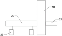
fig. 4 is the utility model relates to a frame plate in the automatic special plane of new forms of energy pipe fitting is connected the structure chart of orthographic view with the horizontal pole.
In the figure: 1. a saddle; 2. supporting legs; 3. a support table; 4. a hydraulic lever; 5. a cutter; 6. a control panel; 7. a support plate; 8. a first motor; 9. a feed roller; 10. a fixed seat; 11. a groove; 12. a screw; 13. a movable seat; 14. a splint; 15. a second motor; 16. a belt pulley; 17. a drive belt; 18. a frame plate; 19. a through groove; 20. moving the plate; 21. inserting a rod; 22. a cross bar; 23. an electric telescopic rod; 24. an inductor.
Detailed Description
The technical solutions in the embodiments of the present invention will be described clearly and completely with reference to the accompanying drawings in the embodiments of the present invention, and it is obvious that the described embodiments are only some embodiments of the present invention, not all embodiments. Based on the embodiments in the present invention, all other embodiments obtained by a person skilled in the art without creative work belong to the protection scope of the present invention.
Referring to fig. 1-4, the present invention provides a technical solution: the utility model provides an automatic special plane of new forms of energy pipe fitting, includes:
the device comprises a support table 1, four supporting legs 2 are fixedly welded on the bottom side of the support table 1, a support table 3 is fixedly welded on the top side of the support table 1, a hydraulic rod 4 is fixedly installed on the support table 3, a cutting machine 5 is fixedly installed at the bottom end of the hydraulic rod 4, and a control panel 6 is fixedly installed on the support table 1;
the feeding mechanism is arranged at the right edge of the top side of the saddle 1;
the clamping mechanism is arranged in the middle of the top side of the supporting table 1;
and the blanking mechanism is arranged at the edge of the left side of the top side of the saddle 1.
The feeding mechanism comprises two supporting plates 7, the bottom sides of the two supporting plates 7 are fixedly welded with the top side of the supporting table 1, a first motor 8 is fixedly installed on the outer side of one supporting plate 7, two feeding rollers 9 are connected between the two supporting plates 7 in a rotating mode, a rotating shaft of each feeding roller 9 on the bottom side is fixedly welded with an output shaft of the corresponding first motor 8, the corresponding first motor 8 is connected with the control panel 6 through a wire, and the feeding mechanism drives the feeding rollers 9 on the bottom side to rotate through the corresponding first motor 8, so that the pipe fitting can slide and move between the two feeding rollers 9.
Fixture includes two fixing bases 10 and second motor 15, recess 11 has been seted up on the 10 top sides of fixing base, be provided with screw rod 12 in the recess 11, set up two sections screw threads that the pitch equals, the spiral shell is opposite on the screw rod 12, screw rod 12 one end runs through fixing base 10 and rotates with the 10 lateral walls of fixing base to be connected, threaded connection has two to remove seat 13 on the screw rod 12, two remove the equal sliding connection of seat 13 in recess 11, remove the fixed welding in 13 top sides of seat and have splint 14, when screw rod 12 is when rotating, two remove seat 13 can be along with turning to of screw rod 12 and move in opposite directions or dorsad to drive two splint 14 and carry out the centre gripping or loosen to the pipe fitting.
Unloading mechanism includes frame plate 18 and two electric telescopic handle 23, frame plate 18 bottom side and the fixed welding of saddle 1, logical groove 19 has been seted up on the frame plate 18, it has movable plate 20 to lead to sliding connection in the groove 19, the fixed welding of one side that movable plate 20 is close to splint 14 has inserted bar 21, be provided with inductor 24 on the movable plate 20, inductor 24 passes through electric wire connection with control panel 6, and the hollow of pipe fitting is convenient for insert by inserted bar 21 for support the pipe fitting that the cutting was accomplished, can drive the pipe fitting rebound on frame plate 18 through movable plate 20 simultaneously, be convenient for lift the pipe fitting off.
Two electric telescopic handle 23 fixed mounting is on saddle 1, two electric telescopic handle 23 goes up fixed welding and has horizontal pole 22, the fixed welding in one side that inserted bar 21 was kept away from to horizontal pole 22 one end and movable plate 20, two electric telescopic handle 23 all passes through electric wire connection with control panel 6, and electric telescopic handle 23 accessible horizontal pole 22 drives movable plate 20 and reciprocates.
The working principle is as follows: when the utility model is used, the first motor 8 is started through the control panel 6, the first motor 8 drives the feeding rollers 9 at the bottom side to rotate, the end of the pipe fitting is placed between the two feeding rollers 9, the pipe fitting is driven to slide and move towards the frame plate 18 through the rotation of the feeding rollers 9, when the pipe fitting is moved and sleeved on the inserted bar 21 and the end of the pipe fitting is contacted with the inductor 24 on the movable plate 20, the control panel 6 closes the first motor 8, the second motor 15 is started to rotate forwards, the second motor 15 can drive the two screw rods 12 to synchronously rotate simultaneously through the two belt pulleys 16 and the transmission belt 17, when the two screw rods 12 rotate forwards, the two respective moving seats 13 on the two fixed seats 10 are respectively driven to move towards each other, so that the two respective clamping plates 14 on the two fixed seats 10 clamp and fix the pipe fitting, at the moment, the hydraulic rod 4 and the cutting machine 5 are started to cut the pipe fitting, after the cutting is finished, the hydraulic rod 4 and the cutting machine 5 are closed, the second motor 15 is started to rotate reversely, the clamping plate 14 is enabled to loosen the pipe fitting, after the pipe fitting is loosened, the electric telescopic rod 23 drives the moving plate 20 to move upwards through the cross rod 22, the inserting rod 21 is enabled to support the pipe fitting after the cutting to move to the top end of the through groove 19, the pipe fitting after the cutting is taken out, the inductor 24 enables the electric telescopic rod 23 to reset through the control panel 6, meanwhile, the first motor 8 is started to drive the remaining pipe fitting to move, and the operation is repeated to carry out the next cutting.
It is noted that, herein, relational terms such as first and second, and the like may be used solely to distinguish one entity or action from another entity or action without necessarily requiring or implying any actual such relationship or order between such entities or actions. Also, the terms "comprises," "comprising," or any other variation thereof, are intended to cover a non-exclusive inclusion, such that a process, method, article, or apparatus that comprises a list of elements does not include only those elements but may include other elements not expressly listed or inherent to such process, method, article, or apparatus.
Although embodiments of the present invention have been shown and described, it will be appreciated by those skilled in the art that changes, modifications, substitutions and alterations can be made in these embodiments without departing from the principles and spirit of the invention, the scope of which is defined in the appended claims and their equivalents.
Claims (6)
1. The utility model provides an automatic special plane of new forms of energy pipe fitting which characterized in that includes:
the device comprises a supporting table (1), four supporting legs (2) are fixedly welded on the bottom side of the supporting table (1), a supporting table (3) is fixedly welded on the top side of the supporting table (1), a hydraulic rod (4) is fixedly installed on the supporting table (3), a cutting machine (5) is fixedly installed at the bottom end of the hydraulic rod (4), and a control panel (6) is fixedly installed on the supporting table (1);
the feeding mechanism is arranged at the right edge of the top side of the saddle (1);
the clamping mechanism is arranged in the middle of the top side of the supporting table (1);
the blanking mechanism is arranged at the edge of the left side of the top side of the saddle (1).
2. The automatic special machine of new forms of energy pipe fitting of claim 1, characterized in that: the feeding mechanism comprises two supporting plates (7), the bottom sides of the two supporting plates (7) are fixedly welded with the top side of the supporting platform (1), a first motor (8) is fixedly installed on the outer side of one supporting plate (7), two feeding rollers (9) are rotatably connected between the two supporting plates (7), a rotating shaft of each feeding roller (9) on the bottom side is fixedly welded with an output shaft of the corresponding first motor (8), and the corresponding first motor (8) is connected with the control panel (6) through an electric wire.
3. The automatic special plane of new forms of energy pipe fitting of claim 1, characterized in that: fixture includes two fixing bases (10) and second motor (15), recess (11) have been seted up to fixing base (10) top side, be provided with screw rod (12) in recess (11), set up two sections screw threads that pitch equals, the spiral shell is opposite on screw rod (12), screw rod (12) one end is run through fixing base (10) and is rotated with fixing base (10) lateral wall and be connected, threaded connection has two to remove seat (13), two on screw rod (12) remove equal sliding connection of seat (13) in recess (11), it has splint (14) to remove the fixed welding of seat (13) top side.
4. The automatic special machine of new forms of energy pipe fitting of claim 3, characterized in that: second motor (15) fixed mounting is on saddle (1) top side, the output shaft and a screw rod (12) fixed welding of second motor (15), two the surface that fixing base (10) that correspond the position were stretched out in screw rod (12) all fixed welding have belt pulley (16), two belt pulley (16) are connected through drive belt (17) transmission, second motor (15) pass through connection of electric lines with control panel (6).
5. The automatic special machine of new forms of energy pipe fitting of claim 1, characterized in that: unloading mechanism includes frame plate (18) and two electric telescopic handle (23), frame plate (18) bottom side and saddle (1) fixed welding, logical groove (19) have been seted up on frame plate (18), it has movable plate (20) to lead to sliding connection in groove (19), one side fixed welding that movable plate (20) are close to splint (14) has inserted bar (21), be provided with inductor (24) on movable plate (20), inductor (24) pass through electric wire connection with control panel (6).
6. The automatic special machine of new forms of energy pipe fitting of claim 5, characterized in that: two electric telescopic handle (23) fixed mounting is on saddle (1), two electric telescopic handle (23) are gone up fixed welding and are had horizontal pole (22), the fixed welding in one side of inserted bar (21) is kept away from to horizontal pole (22) one end and movable plate (20), two electric telescopic handle (23) all pass through the connection of electric lines with control panel (6).
Priority Applications (1)
| Application Number | Priority Date | Filing Date | Title |
|---|---|---|---|
| CN202220931449.XU CN217166728U (en) | 2022-04-21 | 2022-04-21 | Automatic special plane of new forms of energy pipe fitting |
Applications Claiming Priority (1)
| Application Number | Priority Date | Filing Date | Title |
|---|---|---|---|
| CN202220931449.XU CN217166728U (en) | 2022-04-21 | 2022-04-21 | Automatic special plane of new forms of energy pipe fitting |
Publications (1)
| Publication Number | Publication Date |
|---|---|
| CN217166728U true CN217166728U (en) | 2022-08-12 |
Family
ID=82708188
Family Applications (1)
| Application Number | Title | Priority Date | Filing Date |
|---|---|---|---|
| CN202220931449.XU Active CN217166728U (en) | 2022-04-21 | 2022-04-21 | Automatic special plane of new forms of energy pipe fitting |
Country Status (1)
| Country | Link |
|---|---|
| CN (1) | CN217166728U (en) |
Cited By (2)
| Publication number | Priority date | Publication date | Assignee | Title |
|---|---|---|---|---|
| CN115121862A (en) * | 2022-08-31 | 2022-09-30 | 江苏盐城苏凌机械有限公司 | Efficient automatic cutting machine for metal square tube |
| CN116174795A (en) * | 2023-02-28 | 2023-05-30 | 宝玛克(合肥)科技有限公司 | Automatic fixed-point cutting equipment for new energy material magnesium aluminum alloy |
-
2022
- 2022-04-21 CN CN202220931449.XU patent/CN217166728U/en active Active
Cited By (2)
| Publication number | Priority date | Publication date | Assignee | Title |
|---|---|---|---|---|
| CN115121862A (en) * | 2022-08-31 | 2022-09-30 | 江苏盐城苏凌机械有限公司 | Efficient automatic cutting machine for metal square tube |
| CN116174795A (en) * | 2023-02-28 | 2023-05-30 | 宝玛克(合肥)科技有限公司 | Automatic fixed-point cutting equipment for new energy material magnesium aluminum alloy |
Similar Documents
| Publication | Publication Date | Title |
|---|---|---|
| CN217166728U (en) | Automatic special plane of new forms of energy pipe fitting | |
| CN211439034U (en) | Auto-parts clamping device | |
| CN215698417U (en) | Section bar cutting equipment is used in door and window production | |
| CN218253262U (en) | Tapping machine for hardware processing | |
| CN218016566U (en) | Finished product stepping pushing mechanism for automatic network-surfing welding machine for eyebrow trimming blade | |
| CN218016570U (en) | A blade feeding mechanism for automatic online welding machine of eyebrow plucker blade | |
| CN215746831U (en) | Multi-cutter-row pipe grooving machine | |
| CN215431825U (en) | Aluminum bar sawing machine cutting device for door and window aluminum product production | |
| CN110509087B (en) | Spring chuck clamp | |
| CN210997239U (en) | Sheet metal component welding pen fixture | |
| CN210908804U (en) | Automatic assembly device for head shell and rotor of angle grinder | |
| CN219837482U (en) | Clamp for machining motor shell | |
| CN207746470U (en) | A kind of automatic pipe cutting equipment | |
| CN219484983U (en) | Numerical control machine tool clamping device for machining threads of threaded rod | |
| CN219648873U (en) | Tapping machine processing locking mechanism | |
| CN220095510U (en) | Processing frock of box body | |
| CN213592126U (en) | Positioning device for stainless steel welding | |
| CN221694873U (en) | Sheet metal clamping device for sheet metal bending machine | |
| CN219426992U (en) | Corner cutting machine for photo frame processing | |
| CN220533125U (en) | Sawing machine feeding frame and sawing machine | |
| CN220971159U (en) | Laser cutting device convenient to fix | |
| CN219542382U (en) | Clamping device for machining of die milling machine | |
| CN213916403U (en) | Cutting device is used in stainless steel pipe fitting production and processing | |
| CN216325773U (en) | Indirect projection welding clamp | |
| CN219786461U (en) | Positioning fixture for automatic forging of net rack fittings |
Legal Events
| Date | Code | Title | Description |
|---|---|---|---|
| GR01 | Patent grant | ||
| GR01 | Patent grant |