CN217161471U - Semi-automatic lifting chair for rehabilitation bedside - Google Patents
Semi-automatic lifting chair for rehabilitation bedside Download PDFInfo
- Publication number
- CN217161471U CN217161471U CN202220227082.3U CN202220227082U CN217161471U CN 217161471 U CN217161471 U CN 217161471U CN 202220227082 U CN202220227082 U CN 202220227082U CN 217161471 U CN217161471 U CN 217161471U
- Authority
- CN
- China
- Prior art keywords
- hinge plate
- base
- platform
- semi
- bedside
- Prior art date
- Legal status (The legal status is an assumption and is not a legal conclusion. Google has not performed a legal analysis and makes no representation as to the accuracy of the status listed.)
- Expired - Fee Related
Links
- 229910001220 stainless steel Inorganic materials 0.000 claims description 3
- 239000010935 stainless steel Substances 0.000 claims description 3
- 239000010985 leather Substances 0.000 description 3
- 238000012856 packing Methods 0.000 description 3
- 230000004048 modification Effects 0.000 description 2
- 238000012986 modification Methods 0.000 description 2
- 230000002265 prevention Effects 0.000 description 2
- 230000009286 beneficial effect Effects 0.000 description 1
- 238000005260 corrosion Methods 0.000 description 1
- 230000007797 corrosion Effects 0.000 description 1
- 238000009434 installation Methods 0.000 description 1
- 238000000034 method Methods 0.000 description 1
- NJPPVKZQTLUDBO-UHFFFAOYSA-N novaluron Chemical compound C1=C(Cl)C(OC(F)(F)C(OC(F)(F)F)F)=CC=C1NC(=O)NC(=O)C1=C(F)C=CC=C1F NJPPVKZQTLUDBO-UHFFFAOYSA-N 0.000 description 1
- 230000003647 oxidation Effects 0.000 description 1
- 238000007254 oxidation reaction Methods 0.000 description 1
- 230000002035 prolonged effect Effects 0.000 description 1
Images


Abstract
The utility model discloses a semi-automatic lift chair in recovered bedside, its technical scheme main points are: the seat comprises a seat component, a platform, hinge plate components and a base, wherein a square groove is formed in the base, a hydraulic pump is arranged in the square groove, a hydraulic pedal is arranged on the left side of the base, the lower end of a left hinge plate is hinged with the upper part of the base, the upper end of a right hinge plate is hinged with the bottom of the platform, sliding grooves are formed in the positions, corresponding to the upper part of the base and the lower part of the platform, pulleys are fixedly arranged above the left hinge plate and below the right hinge plate, a connecting rod is fixedly arranged between the two right hinge plates, and a push rod of the hydraulic pump and the upper part of the platform are fixedly connected with the connecting rod; the utility model provides an inconvenient user of lift chair carry out the problem of quick lift processing and lift chair's structure setting singleness to the chair body, do not possess safeguard function, influence the problem that user's use was experienced.
Description
Technical Field
The utility model belongs to the technical field of the technique of chair and specifically relates to recovered bedside semi-automatic lift chair.
Background
At present, various fall prevention measures are adopted by different hospitals, wherein the fall prevention measures comprise adjustable seats, but for the condition that the old people need to take care alone, medical staff needs to face a large number of different patients, the work is busy, and each patient is difficult to be simultaneously and effectively seen. At this time, a convenient chair is needed to help medical personnel improve the level of care for elderly patients.
Referring to the current chinese patent with publication number CN212326861U, a lifting chair for medical care is disclosed, comprising a seat plate, a first plug-in rod, a lifting hole, a lifting plate, a rack, a supportable adjusting seat structure, a rotatable adjusting relying plate structure, an adjustable anti-skid pedal structure, a rubber pad, a handrail connecting rod, a handrail rod, a plug box, a bolt, a first supporting tube and a transverse connecting rod.
However, the lifting chair still has some disadvantages, and the lifting chair is inconvenient for a user to carry out rapid lifting treatment on the chair body; the structure of lift chair sets up singlely, does not possess safeguard function, influences user's use and experiences.
SUMMERY OF THE UTILITY MODEL
To the problem that mentions in the background art, the utility model aims at providing a semi-automatic lift chair in recovered bedside to the inconvenient user of lift chair who mentions in the solution background art sets up singlely to the structure that the problem that the chair body goes on going up and down fast to handle and lift chair, does not possess safeguard function, influences the problem that user's use was experienced.
The above technical purpose of the present invention can be achieved by the following technical solutions:
semi-automatic lift chair in recovered bedside, including the seat subassembly, the platform, the hinge plate subassembly, a pedestal, the square groove has been seted up on the base, be provided with the hydraulic pump in the square groove, be provided with hydraulic pedal on the left side of base, the hinge plate subassembly is by left hinge plate, right hinge plate is constituteed, left hinge plate, crossing hinged joint between the right hinge plate, the lower extreme of left hinge plate and the top hinged joint of base, the upper end of right hinge plate and the bottom hinged joint of platform, the spout has been seted up to the top of base and the platform below corresponding position department, the top of left hinge plate and the fixed pulley that is provided with in below of right hinge plate, pulley and spout sliding connection that correspond, the fixed connecting rod that is provided with between two right hinge plates, the push rod and the connecting rod fixed connection of hydraulic pump, the top of platform is provided with the seat subassembly.
Furthermore, the seat component comprises a seat body, armrests, fixed stand columns and a bottom ring, wherein the armrests are fixedly arranged on the seat body, the fixed stand columns are fixedly arranged at the bottom of the seat body, and the bottom ring is fixedly arranged below the fixed stand columns.
Furthermore, a plurality of positioning holes are formed in the bottom ring, and a plurality of fixing holes are formed in the platform.
Furthermore, the handrail, the fixed upright post and the bottom ring are made of stainless steel.
Furthermore, safety belts are fixedly arranged on two sides of the backrest of the chair body.
Furthermore, the four corners of the bottom of the base are fixedly provided with rollers.
To sum up, the utility model discloses mainly have following beneficial effect:
1. the utility model discloses a, through the user to hydraulic pedal's pushing down for the push rod of hydraulic pump promotes the connecting rod, removes on pulley and the spout, and the structure setting of cooperation hinge plate subassembly makes to stretch out and draw back the hinge plate subassembly, and then goes up and down to the platform, makes to go up and down to handle the seat subassembly.
2. The utility model discloses a, structure setting through the seat subassembly, the back of the chair body is made by the sponge of genuine leather parcel, promote user's use and experience, the fixed safety belt that is provided with on the back both sides of the chair body, the end fixing of safety belt is provided with the magic subsides, on going on the stable constraint of user to the chair body, the inside packing of safety belt has the sponge, promote user's use and experience, the fixed gyro wheel that is provided with in bottom four corners department of base, the gyro wheel is for from locking-type universal wheel, the person of facilitating the use removes semi-automatic lift chair.
Drawings
The accompanying drawings are included to provide a further understanding of the invention, and are incorporated in and constitute a part of this specification, illustrate embodiments of the invention, and together with the description serve to explain the invention and not to limit the invention. In the drawings:
fig. 1 is a schematic structural view of the present invention;
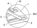
FIG. 2 is an enlarged view taken at A in FIG. 1;
fig. 3 is an enlarged view at B in fig. 1.
In the figure: 1. a seat assembly; 101. a chair body; 102. a handrail; 103. fixing the upright post; 104. a bottom ring; 2. a platform; 3. a hinge plate assembly; 301. a left hinge plate; 302. a right hinge plate; 4. a base; 5. a square groove; 6. a hydraulic pump; 7. a hydraulic pedal; 8. a chute; 9. a pulley; 10. a connecting rod; 11. a seat belt; 12. and a roller.
Detailed Description
In order to make the objects and technical solutions of the present invention clear and fully described, and the advantages thereof more clearly understood, the embodiments of the present invention are described in further detail below with reference to the accompanying drawings.
In the description of the present invention, it should be noted that the terms "center", "upper", "lower", "left", "right", "inner", "outer", "top", "bottom", "side", "vertical", "horizontal", and the like indicate the orientation or positional relationship based on the orientation or positional relationship shown in the drawings, and are only for convenience of description and simplification of description, but do not indicate or imply that the device or element referred to must have a specific orientation, be constructed and operated in a specific orientation, and thus, should not be construed as limiting the present invention. Furthermore, the terms "first," "second," "third," "fourth," "fifth," and "sixth" are used for descriptive purposes only and are not to be construed as indicating or implying relative importance.
In the description of the present invention, it should be noted that, unless otherwise explicitly specified or limited, the terms "mounted," "connected" and "connected" are to be construed broadly, and may be, for example, fixedly connected, detachably connected, or integrally connected; can be mechanically or electrically connected; they may be connected directly or indirectly through intervening media, or they may be interconnected between two elements. The specific meaning of the above terms in the present invention can be understood in specific cases to those skilled in the art.
Example 1
Referring to fig. 1-3, a semi-automatic lifting chair for rehabilitation bedside comprises a seat component 1, a platform 2, a hinge plate component 3 and a base 4, wherein the bedside lifting chair for patients to get on and off the bed in hospitals can accompany family members to sit at ordinary times, the base 4 is provided with a square groove 5, the square groove 5 is internally provided with a hydraulic pump 6, the left side of the base 4 is provided with a hydraulic pedal 7, the hydraulic pedal 7 is fixedly connected with the hydraulic pump 6, a push rod of the hydraulic pump 6 pushes a connecting rod 10 by pressing down the hydraulic pedal 7, so that the hinge plate component 3 is lifted, the seat component 1 is lifted, the telescopic range of the hinge plate component 3 is 21-72 cm, the hinge plate component 3 consists of a left hinge plate 301 and a right hinge plate 302, the left hinge plate 301 and the right hinge plate 302 are connected by a cross hinge, the lower end of the left hinge plate 301 is hinged with the upper part of the base 4, the upper end of right hinge board 302 and platform 2's bottom hinged joint, base 4's top and platform 2 below correspond position department and have seted up spout 8, the fixed pulley 9 that is provided with in top and the below of right hinge board 302 of left side hinge board 301, pulley 9 and the 8 sliding connection of spout that correspond, the fixed connecting rod 10 that is provided with between two right hinge boards 302, remove on pulley 9 and the spout 8, the structure setting of cooperation hinge board subassembly 3, go up and down to platform 2, make and go up and down to handle seat subassembly 1, the push rod and the connecting rod 10 fixed connection of hydraulic pump 6, platform 2's top is provided with seat subassembly 1.
Referring to fig. 1 and 3, the seat assembly 1 is composed of a seat body 101, an armrest 102, a fixed upright post 103 and a bottom ring 104, a backrest of the seat body 101 is made of sponge wrapped by leather, so that the use experience of a user is improved, the armrest 102 is fixedly arranged on the seat body 101, a rubber layer is fixedly arranged on the surface of the armrest 102 and protects the user, the fixed upright post 103 is fixedly arranged at the bottom of the seat body 101, the bottom ring 104 is fixedly arranged below the fixed upright post 103, and the stability of the installation connection of the seat assembly 1 and the platform 2 is improved.
Referring to fig. 1 and 3, a plurality of positioning holes are formed in the bottom ring 104, a plurality of fixing holes are formed in the platform 2, and the corresponding positioning holes and the corresponding fixing holes are fixedly connected through fixing bolts, so that a user can install the seat assembly 1 and the platform 2 quickly.
Referring to fig. 1 and 3, the handrail 102, the fixed upright posts 103 and the bottom ring 104 are made of stainless steel, so that the handrail 102, the fixed upright posts 103 and the bottom ring 104 have high corrosion resistance and oxidation resistance, and the service life of the handrail 102, the fixed upright posts 103 and the bottom ring 104 is prolonged.
Referring to fig. 1, the fixed safety belt 11 that is provided with on the back both sides of the chair body 101, the end fixing of safety belt 11 is provided with the magic subsides, carries out stable constraint with the user to the chair body 101 on, and the inside packing of safety belt 11 has the sponge, promotes user's use and experiences.
Referring to fig. 1, the four corners of the bottom of the base 4 are fixedly provided with rollers 12, and the rollers 12 are self-locking universal wheels, so that a user can move the semi-automatic lifting chair conveniently.
When the utility model is used, the push rod of the hydraulic pump 6 pushes the connecting rod 10 by pressing the hydraulic pedal 7 down by a user, the pulley 9 and the chute 8 move up and down, and the hinge plate component 3 is stretched and contracted by matching with the structural arrangement of the hinge plate component 3, so that the platform 2 is lifted and lowered, and the seat component 1 is lifted and lowered; through seat subassembly 1's structure setting, the back of chair body 101 is made by the sponge of genuine leather parcel, promote user's use and experience, the fixed safety belt 11 that is provided with on the back both sides of chair body 101, the end fixing of safety belt 11 is provided with the magic subsides, it has the sponge to carry out stable constraint to the user on the chair body 101, the inside packing of safety belt 11 has, promote user's use and experience, the fixed gyro wheel 12 that is provided with in bottom four corners department of base 4, gyro wheel 12 is from locking-type universal wheel, the person of facilitating the use removes semi-automatic lift chair.
Finally, it should be noted that: although the present invention has been described in detail with reference to the foregoing embodiments, it will be apparent to those skilled in the art that modifications may be made to the embodiments described above, or equivalents may be substituted for elements thereof. Any modification, equivalent replacement, or improvement made within the spirit and principle of the present invention should be included in the protection scope of the present invention.
Claims (6)
1. Recovered bedside semi-automatic lift chair, including seat subassembly (1), platform (2), hinge board subassembly (3), base (4), its characterized in that: a square groove (5) is formed in the base (4), a hydraulic pump (6) is arranged in the square groove (5), a hydraulic pedal (7) is arranged on the left side of the base (4), the hinge plate assembly (3) is composed of a left hinge plate (301) and a right hinge plate (302), the left hinge plate (301) and the right hinge plate (302) are connected through a cross hinge, the lower end of the left hinge plate (301) is connected with the upper side of the base (4) through a hinge, the upper end of the right hinge plate (302) is connected with the bottom of the platform (2) through a hinge, sliding grooves (8) are formed in the positions, corresponding to the upper side of the base (4) and the lower side of the platform (2), pulleys (9) are fixedly arranged above the left hinge plate (301) and the lower side of the right hinge plate (302), the corresponding pulleys (9) are connected with the sliding grooves (8) in a sliding manner, and a connecting rod (10) is fixedly arranged between the two right hinge plates (302), the push rod and the connecting rod (10) fixed connection of hydraulic pump (6), the top of platform (2) is provided with seat subassembly (1).
2. The rehabilitation bedside semi-automatic lifting chair according to claim 1, characterized in that: the seat assembly (1) comprises a seat body (101), armrests (102), fixed upright posts (103) and a bottom ring (104), wherein the armrests (102) are fixedly arranged on the seat body (101), the fixed upright posts (103) are fixedly arranged at the bottom of the seat body (101), and the bottom ring (104) is fixedly arranged below the fixed upright posts (103).
3. The rehabilitation bedside semi-automatic lifting chair according to claim 2, characterized in that: a plurality of positioning holes are formed in the bottom ring (104), and a plurality of fixing holes are formed in the platform (2).
4. The semi-automatic lifting chair for rehabilitation bedside according to claim 3, characterized in that: the handrail (102), the fixed upright post (103) and the bottom ring (104) are made of stainless steel.
5. The rehabilitation bedside semi-automatic lifting chair according to claim 4, characterized in that: safety belts (11) are fixedly arranged on two sides of the backrest of the chair body (101).
6. The rehabilitation bedside semi-automatic lifting chair according to claim 1, characterized in that: and rollers (12) are fixedly arranged at the four corners of the bottom of the base (4).
Priority Applications (1)
| Application Number | Priority Date | Filing Date | Title |
|---|---|---|---|
| CN202220227082.3U CN217161471U (en) | 2022-01-27 | 2022-01-27 | Semi-automatic lifting chair for rehabilitation bedside |
Applications Claiming Priority (1)
| Application Number | Priority Date | Filing Date | Title |
|---|---|---|---|
| CN202220227082.3U CN217161471U (en) | 2022-01-27 | 2022-01-27 | Semi-automatic lifting chair for rehabilitation bedside |
Publications (1)
| Publication Number | Publication Date |
|---|---|
| CN217161471U true CN217161471U (en) | 2022-08-12 |
Family
ID=82736736
Family Applications (1)
| Application Number | Title | Priority Date | Filing Date |
|---|---|---|---|
| CN202220227082.3U Expired - Fee Related CN217161471U (en) | 2022-01-27 | 2022-01-27 | Semi-automatic lifting chair for rehabilitation bedside |
Country Status (1)
| Country | Link |
|---|---|
| CN (1) | CN217161471U (en) |
-
2022
- 2022-01-27 CN CN202220227082.3U patent/CN217161471U/en not_active Expired - Fee Related
Similar Documents
| Publication | Publication Date | Title |
|---|---|---|
| CN105326614B (en) | A kind of pregnant multifunctional wheelchair of the old,weak,sick and disabled | |
| CN111249094A (en) | Auxiliary supporting equipment for clinical treatment of middle-aged and old people | |
| CN217161471U (en) | Semi-automatic lifting chair for rehabilitation bedside | |
| CN210185891U (en) | Nursing bed | |
| CN216676145U (en) | Wheelchair bed | |
| CN213406662U (en) | Bed patient stands up bed convenient to adjust | |
| CN207734284U (en) | A kind of clinical care wheelchair | |
| CN213099172U (en) | Old patient uses walking auxiliary device | |
| CN213098901U (en) | Width-adjustable sickbed | |
| CN211023559U (en) | Portable stair wheelchair stretcher | |
| CN210932338U (en) | Anti-slip sickbed | |
| TWM582384U (en) | Nursing robot | |
| CN211326257U (en) | Old person's nursing bed of posture is adjusted according to actual conditions | |
| CN213641891U (en) | Height-adjustable's inspection chair for paediatrics | |
| CN214549647U (en) | Height-adjustable stepping stool for operation | |
| CN215779321U (en) | Multifunctional nursing bed with adjustable height | |
| CN220158579U (en) | Wheelchair | |
| CN212261836U (en) | Muscle attenuation syndrome falling prevention device | |
| CN213788338U (en) | Nursing bed for first aid | |
| CN211934574U (en) | Emergency call nursing is with horizontal stretcher | |
| CN214761857U (en) | Hospital patient prevents falling device with wheelchair | |
| CN215350466U (en) | Adjustable walking assisting device for old people rehabilitation nursing | |
| CN213076268U (en) | Medical care shallow is used in paediatrics nursing | |
| CN212788947U (en) | Multifunctional folding bed | |
| CN218420261U (en) | Medical nursing bed |
Legal Events
| Date | Code | Title | Description |
|---|---|---|---|
| GR01 | Patent grant | ||
| GR01 | Patent grant | ||
| CF01 | Termination of patent right due to non-payment of annual fee | ||
| CF01 | Termination of patent right due to non-payment of annual fee |
Granted publication date: 20220812 |