CN217139830U - Industrial VOCs waste gas decomposition and purification device - Google Patents
Industrial VOCs waste gas decomposition and purification device Download PDFInfo
- Publication number
- CN217139830U CN217139830U CN202123364207.1U CN202123364207U CN217139830U CN 217139830 U CN217139830 U CN 217139830U CN 202123364207 U CN202123364207 U CN 202123364207U CN 217139830 U CN217139830 U CN 217139830U
- Authority
- CN
- China
- Prior art keywords
- purification
- pipe
- tank
- waste gas
- purifying
- Prior art date
- Legal status (The legal status is an assumption and is not a legal conclusion. Google has not performed a legal analysis and makes no representation as to the accuracy of the status listed.)
- Active
Links
Images


Classifications
-
- Y—GENERAL TAGGING OF NEW TECHNOLOGICAL DEVELOPMENTS; GENERAL TAGGING OF CROSS-SECTIONAL TECHNOLOGIES SPANNING OVER SEVERAL SECTIONS OF THE IPC; TECHNICAL SUBJECTS COVERED BY FORMER USPC CROSS-REFERENCE ART COLLECTIONS [XRACs] AND DIGESTS
- Y02—TECHNOLOGIES OR APPLICATIONS FOR MITIGATION OR ADAPTATION AGAINST CLIMATE CHANGE
- Y02A—TECHNOLOGIES FOR ADAPTATION TO CLIMATE CHANGE
- Y02A50/00—TECHNOLOGIES FOR ADAPTATION TO CLIMATE CHANGE in human health protection, e.g. against extreme weather
- Y02A50/20—Air quality improvement or preservation, e.g. vehicle emission control or emission reduction by using catalytic converters
Landscapes
- Treating Waste Gases (AREA)
Abstract
An industrial VOCs waste gas decomposition and purification device relates to the technical field of waste gas treatment, and comprises a purification tank and a filter tank, the filter tank is arranged at one side of the purification tank, a transfer case is fixedly arranged on the inner wall of the bottom of the purification tank, one side of the transfer box is connected with a middle pipe, one end of the middle pipe far away from the transfer box is connected with one side of the filter tank, the top end of the transfer box is connected with a vertical pipe, the interior of the purification tank is provided with a plurality of purification pipes which are distributed at equal intervals from top to bottom, two adjacent purification pipes are communicated through a connecting pipe, the purification pipes are arranged from top to bottom and are communicated through the connecting pipe, the purification pipes and the connecting pipe are combined to form an S-shaped structure, the residence time of the waste gas in the purifying pipe can be prolonged, the purification is more thorough, the secondary purification is not needed, and the decomposition and purification efficiency of the industrial VOCs waste gas is improved.
Description
Technical Field
The utility model relates to a waste gas treatment technical field especially relates to industry VOCs waste gas decomposes purifier.
Background
VOCs refer to volatile organic compounds, and are generally classified into non-methane hydrocarbons, oxygen-containing organic compounds, halogenated hydrocarbons, nitrogen-containing organic compounds, sulfur-containing organic compounds, and the like. VOCs participate in the formation of ozone and secondary aerosols in the atmospheric environment, which have important effects on regional atmospheric ozone pollution and PM2.5 pollution.
The waste gas decomposition and purification of industrial VOCs generally adopts photocatalytic decomposition, and the technical principle of the photocatalytic decomposition is that a photocatalyst such as TiO 2 Is activated under ultraviolet irradiation to make gaseous H 2 O generates OH free radical and ozone and other strong oxidizing substances, and then VOCs pollutants are oxidized into CO 2 And H 2 And O. However, the purification device in the prior art has the problem that the time for passing the waste gas in the pipeline is insufficient, so that the photocatalytic reaction is insufficient, and the waste gas purification effect is influenced.
In order to solve the problems, the application provides an industrial VOCs waste gas decomposition and purification device.
SUMMERY OF THE UTILITY MODEL
Objects of the invention
For solving the technical problem who exists among the background art, the utility model provides an industry VOCs waste gas decomposes purifier, through with the purge tube from last to arranging and set up the connecting pipe down with each purge tube intercommunication, the purge tube forms the S-shaped structure with the connecting pipe combination, can prolong the dwell time of waste gas in the purge tube, it is more thorough to make the purification, do not need the secondary purification, improve industry VOCs waste gas and decompose purification efficiency, it is not enough to have waste gas transit time in the pipeline with the purifier who solves among the prior art, lead to the insufficient problem of photocatalytic reaction.
(II) technical scheme
In order to solve the problems, the utility model provides an industrial VOCs waste gas decomposition and purification device, which comprises a purification tank and a filter tank and is characterized in that the filter tank is arranged on one side of the purification tank, a transfer case is fixedly arranged on the inner wall of the bottom of the purification tank, one side of the transfer case is connected with an intermediate pipe, one end of the intermediate pipe, which is far away from the transfer case, is connected with one side of the filter tank, the top end of the transfer case is connected with a vertical pipe, purification pipes are arranged inside the purification tank, the purification pipes are arranged in a plurality and are distributed at equal intervals from top to bottom, two adjacent purification pipes are communicated through a connecting pipe, the purification pipe positioned at the bottom is connected with the vertical pipe, and the purification pipe positioned at the top is connected with an exhaust pipe;
one side of the filtering tank far away from the intermediate pipe is connected with an air inlet pipe, a rotating shaft is arranged inside the filtering tank, two ends of the rotating shaft are rotatably connected with the inner wall of the filtering tank, and the side wall of the rotating shaft is connected with a filtering mechanism.
Preferably, the interior of the purification tube is fixedly provided with a high-energy ultraviolet lamp.
Preferably, the equal fixedly connected with fixed column in purge tube both ends, fixed column one end and the inner wall fixed connection of purifying tank.
Preferably, the top end of the purification tank is connected with an induced air pipe, and a fan is arranged inside the induced air pipe.
Preferably, a motor is fixedly mounted on one side of the filter tank, and the output end of the motor is in transmission connection with the rotating shaft.
Preferably, the filtering mechanism comprises an activated carbon plate, side baffles and an upper pressure plate, the side baffles are arranged at two ends of the activated carbon plate and distributed at the two ends of the activated carbon plate, the bottom ends of the side baffles are fixedly connected with the side wall of the rotating shaft, the upper pressure plate is pressed on the top end of the activated carbon plate, insertion blocks are fixedly connected to two sides of the bottom end of the upper pressure plate, slots are formed in the top ends of the side baffles, the insertion blocks are inserted into the inner sides of the slots, the insertion blocks are fixedly connected with the side baffles through bolts, blocking frames are fixedly connected to two sides of the upper pressure plate, and the blocking frames are located on two sides of the activated carbon plate.
Preferably, the peripheral lateral wall of pivot has seted up the constant head tank, the butt joint of active carbon board bottom is gone into the constant head tank inboard.
The above technical scheme of the utility model has following profitable technological effect:
1. the utility model arranges the purification pipes from top to bottom and arranges the connecting pipes to communicate each purification pipe, and the purification pipes and the connecting pipes are combined to form an S-shaped structure, so that the retention time of waste gas in the purification pipes can be prolonged, the purification is more thorough, secondary purification is not needed, and the decomposition and purification efficiency of industrial VOCs waste gas is improved;
2. the utility model discloses a it is rotatory to drive filtering mechanism filtering tank inside setting up the pivot, can make filtering mechanism and waste gas fully contact, improves filtration efficiency to do not influence gaseous through-put speed.
Drawings
Fig. 1 is a schematic view of the overall structure of the present invention;
FIG. 2 is a schematic view of the internal structure of the purification tank of the present invention;
FIG. 3 is a schematic view of the internal structure of the purification tube of the present invention;
FIG. 4 is a schematic view of the internal structure of the filtration tank of the present invention;
FIG. 5 is a schematic view of the entire structure of the rotating shaft of the present invention;
fig. 6 is a schematic view of the filter mechanism of the present invention.
Reference numerals:
1. a purification tank; 2. a transfer box; 201. an intermediate pipe; 202. a vertical tube; 3. a purge tube; 301. a high-energy ultraviolet lamp; 302. fixing a column; 4. a connecting pipe; 5. an exhaust pipe; 6. an induced draft pipe; 7. a filter tank; 701. an air inlet pipe; 702. a rotating shaft; 703. a motor; 704. positioning a groove; 8. a filtering mechanism; 801. an activated carbon plate; 802. a side dam; 803. an upper pressure plate; 804. inserting a block; 805. a slot; 806. and a blocking frame.
Detailed Description
In order to make the objects, technical solutions and advantages of the present invention more apparent, the present invention will be described in detail with reference to the accompanying drawings. It should be understood that the description is intended to be illustrative only and is not intended to limit the scope of the present invention. Moreover, in the following description, descriptions of well-known structures and techniques are omitted so as to not unnecessarily obscure the concepts of the present invention.
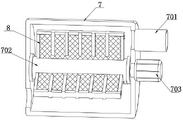
As shown in FIGS. 1-6, the utility model provides an industrial VOCs waste gas decomposition and purification device, which comprises a purification tank 1 and a filtration tank 7, wherein the filtration tank 7 is arranged at one side of the purification tank 1, a transfer case 2 is fixedly arranged at the inner wall of the bottom of the purification tank 1, one side of the transfer case 2 is connected with an intermediate pipe 201, one end of the intermediate pipe 201 far away from the transfer case 2 is connected with one side of the filtration tank 7, the top end of the transfer case 2 is connected with a vertical pipe 202, a purification pipe 3 is arranged inside the purification tank 1, the purification pipes 3 are arranged in a plurality and are distributed at equal intervals from top to bottom, two adjacent purification pipes 3 are communicated through a connecting pipe 4, the purification pipe 3 at the bottom is connected with the vertical pipe 202, the purification pipe 3 at the top is connected with an exhaust pipe 5, the industrial VOCs waste gas enters the interior of the transfer case 2 through the intermediate pipe 201 after being filtered in the filtration tank 7 and then enters the purification pipe 3 through the vertical pipe 202, the purification tubes 3 are arranged from top to bottom, the connecting tubes 4 are arranged to communicate the purification tubes 3, the purification tubes 3 and the connecting tubes 4 are combined to form an S-shaped structure, so that the retention time of waste gas in the purification tubes 3 can be prolonged, the purification is more thorough, secondary purification is not needed, the decomposition and purification efficiency of industrial VOCs waste gas is improved, and the purified waste gas is discharged through the exhaust tube 5;
one side of filtering jar 7 and keeping away from intermediate pipe 201 is connected with intake pipe 701, filter jar 7 inside is equipped with pivot 702, the pivot 702 both ends all rotate with the inner wall of filtering jar 7 and are connected, the lateral wall of pivot 702 is connected with filtering mechanism 8, industry VOCs waste gas passes through intake pipe 701 and gets into inside filtering jar 7, it is rotatory to drive filtering mechanism 8 through setting up pivot 702 in filtering jar 7 inside, can make filtering mechanism 8 and waste gas fully contact, and the efficiency of filtration is improved, and do not influence gaseous through-speed.
In an alternative embodiment, the high-energy ultraviolet lamp 301 is fixedly installed inside the purification tube 3, and the photocatalyst is filled inside the purification tube 3, so that the exhaust gas can be decomposed and purified under the irradiation of the high-energy ultraviolet lamp 301.
In an alternative embodiment, the two ends of the purification tube 3 are fixedly connected with fixing columns 302, one end of each fixing column 302 is fixedly connected with the inner wall of the purification tank 1, and the fixing columns 302 are used for fixing the purification tube 3 inside the purification tank 1.
In an optional embodiment, the top end of the purification tank 1 is connected with an induced air pipe 6, a fan is installed inside the induced air pipe 6, the fan inside the induced air pipe 6 is started, air inside the purification tank 1 is pumped outwards, ozone can be pumped out in time when ozone inside the purification tank 1 leaks, and the ozone is prevented from being deposited in the purification tank 1.
In an alternative embodiment, a motor 703 is fixedly installed on one side of the filter tank 7, an output end of the motor 703 is in transmission connection with the rotating shaft 702, and the motor 703 is used for driving the rotating shaft 702 to rotate.
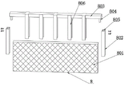
In an optional embodiment, the filtering mechanism 8 includes an activated carbon plate 801, a side baffle 802 and an upper pressure plate 803, the side baffle 802 is provided with two side baffles and distributed at two ends of the activated carbon plate 801, the bottom end of the side baffle 802 is fixedly connected with the side wall of the rotating shaft 702, the upper pressure plate 803 is pressed on the top end of the activated carbon plate 801, both sides of the bottom end of the upper pressure plate 803 are fixedly connected with an insertion block 804, the top end of the side baffle 802 is provided with an insertion slot 805, the insertion block 804 is inserted into the insertion slot 805, the insertion block 804 is fixedly connected with the side baffle 802 through a bolt, both sides of the upper pressure plate 803 are fixedly connected with a blocking frame 806, the blocking frame 806 is located at both sides of the activated carbon plate 801, the upper pressure plate 803, the blocking frame 806 and the side baffle 802 are used for fixing the activated carbon plate 801, the rotating shaft 702 drives the activated carbon plate 801 to rotate, so that the activated carbon plate 801 can be in full contact with exhaust gas, the upper pressure plate 803 and the side baffle 802 are convenient to disassemble and facilitate replacement of the activated carbon plate 801.
In an alternative embodiment, the outer peripheral wall of the rotating shaft 702 is provided with a positioning groove 704, the bottom end of the activated carbon plate 801 is butted into the inner side of the positioning groove 704, and the activated carbon plate 801 is positioned and butted into the positioning groove 704, so that the stability of the activated carbon plate 801 can be improved.
The utility model discloses in, arrange and set up connecting pipe 4 and communicate 3 with each purge tube from last to down with purge tube 3, purge tube 3 forms the S-shaped structure with the combination of connecting pipe 4, can prolong the dwell time of waste gas in purge tube 3, it is more thorough to make the purification, do not need the secondary purification, improve industry VOCs waste gas decomposition purification efficiency, discharge through blast pipe 5 after the purification, it is rotatory to drive filtering mechanism 8 through setting up pivot 702 inside canister 7, can make filtering mechanism 8 fully contact with waste gas, improve filtering efficiency, and do not influence gaseous through-speed, top board 803, fender frame 806 and side shield 802 are used for fixing activated carbon plate 801, pivot 702 drives activated carbon plate 801 and rotates, can make activated carbon plate 801 and waste gas fully contact, top board 803 and side shield 802 easy dismounting, be convenient for activated carbon plate 801 to change.
It is to be understood that the above-described embodiments of the present invention are merely illustrative of or explaining the principles of the invention and are not to be construed as limiting the invention. Therefore, any modification, equivalent replacement, improvement and the like made without departing from the spirit and scope of the present invention should be included in the protection scope of the present invention. Further, it is intended that the appended claims cover all such variations and modifications as fall within the scope and boundaries of the appended claims or the equivalents of such scope and boundaries.
Claims (7)
1. The industrial VOCs waste gas decomposition and purification device comprises a purification tank (1) and a filter tank (7), it is characterized in that the filtering tank (7) is arranged at one side of the purifying tank (1), the inner wall of the bottom of the purifying tank (1) is fixedly provided with a transfer box (2), one side of the transit box (2) is connected with a middle pipe (201), one end of the middle pipe (201) far away from the transit box (2) is connected with one side of the filter tank (7), the top end of the transit box (2) is connected with a vertical pipe (202), a purification pipe (3) is arranged in the purification tank (1), the purification pipes (3) are arranged in a plurality and are distributed at equal intervals from top to bottom, two adjacent purification pipes (3) are communicated through a connecting pipe (4), the purification pipe (3) positioned at the lowest part is connected with the vertical pipe (202), and the purification pipe (3) positioned at the uppermost part is connected with the exhaust pipe (5);
one side of keeping away from intermediate bottom (201) in filter tank (7) is connected with intake pipe (701), filter tank (7) inside is equipped with pivot (702), pivot (702) both ends all are rotated with the inner wall of filtering tank (7) and are connected, the lateral wall of pivot (702) is connected with filtering mechanism (8).
2. The apparatus for decomposing and purifying industrial VOCs waste gas as claimed in claim 1, wherein said purification tubes (3) are fixedly installed with high energy ultraviolet lamps (301) therein.
3. The device for decomposing and purifying industrial VOCs waste gas according to claim 1, wherein fixed columns (302) are fixedly connected to both ends of the purifying pipe (3), and one end of each fixed column (302) is fixedly connected with the inner wall of the purifying tank (1).
4. The waste gas decomposition and purification device for industrial VOCs according to claim 1, wherein an induced draft pipe (6) is connected to the top end of the purification tank (1), and a fan is installed inside the induced draft pipe (6).
5. The device for decomposing and purifying the industrial VOCs waste gas according to the claim 1, wherein a motor (703) is fixedly installed on one side of the filter tank (7), and the output end of the motor (703) is in transmission connection with a rotating shaft (702).
6. The apparatus for decomposing and purifying industrial VOCs waste gas according to claim 1, the filtering mechanism (8) comprises an activated carbon plate (801), a side baffle (802) and an upper pressure plate (803), the side baffle plates (802) are arranged in two and distributed at the two ends of the activated carbon plate (801), the bottom end of the side baffle (802) is fixedly connected with the side wall of the rotating shaft (702), the upper pressure plate (803) is pressed on the top end of the activated carbon plate (801), the two sides of the bottom end of the upper pressure plate (803) are fixedly connected with inserting blocks (804), the top end of the side baffle (802) is provided with an inserting groove (805), the inserting block (804) is inserted into the inner side of the inserting groove (805), the inserting block (804) is fixedly connected with the side baffle (802) through bolts, both sides of the upper pressure plate (803) are fixedly connected with blocking frames (806), and the blocking frames (806) are positioned on both sides of the activated carbon plate (801).
7. The apparatus for decomposing and purifying industrial VOCs waste gas as claimed in claim 6, wherein a positioning groove (704) is formed on the outer peripheral side wall of the rotating shaft (702), and the bottom end of the activated carbon plate (801) is butted against the inner side of the positioning groove (704).
Priority Applications (1)
| Application Number | Priority Date | Filing Date | Title |
|---|---|---|---|
| CN202123364207.1U CN217139830U (en) | 2021-12-30 | 2021-12-30 | Industrial VOCs waste gas decomposition and purification device |
Applications Claiming Priority (1)
| Application Number | Priority Date | Filing Date | Title |
|---|---|---|---|
| CN202123364207.1U CN217139830U (en) | 2021-12-30 | 2021-12-30 | Industrial VOCs waste gas decomposition and purification device |
Publications (1)
| Publication Number | Publication Date |
|---|---|
| CN217139830U true CN217139830U (en) | 2022-08-09 |
Family
ID=82685866
Family Applications (1)
| Application Number | Title | Priority Date | Filing Date |
|---|---|---|---|
| CN202123364207.1U Active CN217139830U (en) | 2021-12-30 | 2021-12-30 | Industrial VOCs waste gas decomposition and purification device |
Country Status (1)
| Country | Link |
|---|---|
| CN (1) | CN217139830U (en) |
-
2021
- 2021-12-30 CN CN202123364207.1U patent/CN217139830U/en active Active
Similar Documents
| Publication | Publication Date | Title |
|---|---|---|
| CN110280117B (en) | Centrifugal oxidation method and micro-nano bubble VOCs (volatile organic chemicals) processing system | |
| CN102824830A (en) | Tubular reactor and method for degrading waste gases with ultraviolet (UV) | |
| CN107754604A (en) | Combination type photocatalysis air purification device | |
| CN217139830U (en) | Industrial VOCs waste gas decomposition and purification device | |
| CN208406570U (en) | A kind of YB-GCH type plasma light catalysis oxidation Waste gas purifying machine | |
| CN213492968U (en) | Energy-efficient SOx/NOx control dust collecting equipment | |
| CN212091693U (en) | Integrated combined purifier | |
| CN111659252A (en) | A decompose and absorb integrative equipment of catalysis for containing ozone's exhaust-gas treatment | |
| CN210251748U (en) | Waste gas purifying equipment | |
| CN112452104A (en) | Waste gas treatment device | |
| CN111266006A (en) | Integrated combined purifier | |
| CN210186823U (en) | Public flue purification device for decomposing peculiar smell of flue gas | |
| CN215901282U (en) | Photocatalyst and photolysis combined type oil smoke purification and collection hood | |
| CN213221665U (en) | Waste incineration flue gas purification device | |
| CN216878527U (en) | Multi-channel waste gas purification device | |
| CN210434305U (en) | Low concentration organic waste gas treatment system | |
| CN212701111U (en) | Novel exhaust-gas treatment equipment | |
| CN209997453U (en) | flue gas purification reactor | |
| CN214345318U (en) | Processing apparatus for exhaust purification | |
| CN212188584U (en) | Waste gas treatment device | |
| CN102824831A (en) | Box-type photoreactor and method for degrading waste gases with ultraviolet (UV) | |
| CN210229538U (en) | VOCs waste gas treatment device for printing factory | |
| CN112058062A (en) | High organic matter waste water environmental protection catalytic reaction device | |
| CN203002191U (en) | Tubular reactor for waste gas degradation by ultraviolet light | |
| CN215276581U (en) | High concentration organic waste gas treatment device |
Legal Events
| Date | Code | Title | Description |
|---|---|---|---|
| GR01 | Patent grant | ||
| GR01 | Patent grant |