CN217137474U - Magnetic conduction pan - Google Patents
Magnetic conduction pan Download PDFInfo
- Publication number
- CN217137474U CN217137474U CN202121002881.2U CN202121002881U CN217137474U CN 217137474 U CN217137474 U CN 217137474U CN 202121002881 U CN202121002881 U CN 202121002881U CN 217137474 U CN217137474 U CN 217137474U
- Authority
- CN
- China
- Prior art keywords
- pot body
- wall
- pot
- heat
- magnetic conduction
- Prior art date
- Legal status (The legal status is an assumption and is not a legal conclusion. Google has not performed a legal analysis and makes no representation as to the accuracy of the status listed.)
- Active
Links
Images


Classifications
-
- Y—GENERAL TAGGING OF NEW TECHNOLOGICAL DEVELOPMENTS; GENERAL TAGGING OF CROSS-SECTIONAL TECHNOLOGIES SPANNING OVER SEVERAL SECTIONS OF THE IPC; TECHNICAL SUBJECTS COVERED BY FORMER USPC CROSS-REFERENCE ART COLLECTIONS [XRACs] AND DIGESTS
- Y02—TECHNOLOGIES OR APPLICATIONS FOR MITIGATION OR ADAPTATION AGAINST CLIMATE CHANGE
- Y02B—CLIMATE CHANGE MITIGATION TECHNOLOGIES RELATED TO BUILDINGS, e.g. HOUSING, HOUSE APPLIANCES OR RELATED END-USER APPLICATIONS
- Y02B40/00—Technologies aiming at improving the efficiency of home appliances, e.g. induction cooking or efficient technologies for refrigerators, freezers or dish washers
Landscapes
- Cookers (AREA)
Abstract
The utility model discloses a magnetic conductive pan, which comprises a pan body, wherein the outer wall of the pan body is provided with a supporting rib, and the outer wall of the bottom of the pan body is also sprayed with a magnetic conductive layer; the support ribs are uniformly arranged around the center of the bottom of the pot body, and the magnetic conduction layer is sprayed on the outer wall of the pot body within the range surrounded by the support ribs. The utility model has the advantages that the outer wall of the pot body of the magnetic conduction pot is provided with the supporting ribs, the pot body is placed on the heating platform through the supporting ribs, and the pot body can be stably placed on the heating platform even if the pot body is heated and deformed; the magnetic conduction layer is sprayed on the outer wall of the pot body, is suitable for heating the induction cooker and is not easy to fall off. The magnetic conduction cookware of the utility model is also provided with heat-resisting ribs and heat-conducting grooves, the heat-resisting ribs reduce heat loss, and simultaneously can prevent the heat from spreading to the position of the cookware handle, thereby reducing the risk of scalding the user; the heat conduction groove increases the heat conductivity of the pot body and reduces energy consumption.
Description
Technical Field
The utility model relates to a cooking utensil technical field, in particular to magnetic conduction pan.
Background
The pot is an essential kitchen utensil in people's daily life. With the continuous development of science and technology and the increasing promotion of people's quality of life, current pan can be suitable for various heating sources usually. The pan of prior art is in order to be applicable to non-naked light heating methods such as electromagnetism stove or electric pottery stove, sets up magnetic conduction piece in the bottom usually, and in order to prevent that the pot body from placing unstably, its pot body bottom generally sets up to the flat bottom. The above structure has the following disadvantages: firstly, the magnetic conductive sheet is generally combined with the pot body through external force, so that the separation risk exists; secondly, the thermal deformation coefficients of the magnetic conductive sheet and the pan body are different, and the pan body with the flat bottom is easy to be heated and deformed in the using process, so that the problem of unstable placement caused by no oil accumulation or outward protrusion due to inward protrusion of the bottom can be caused; thirdly, the pot tool in the prior art also has the defects of low heating efficiency and large energy consumption.
SUMMERY OF THE UTILITY MODEL
An object of the utility model is to solve the not enough of prior art, provide a magnetic conduction pan that can solve the weak point of background art record.
The utility model provides a technical scheme that above-mentioned technical problem adopted is:
a magnetic conductive pan comprises a pan body, wherein the outer wall of the pan body is provided with a supporting rib, and the outer wall of the bottom of the pan body is also sprayed with a magnetic conductive layer; the support ribs are uniformly arranged around the center of the bottom of the pot body, and the magnetic conduction layer is sprayed on the outer wall of the pot body within the range surrounded by the support ribs.
Preferably, the outer wall of the pot body is also provided with a plurality of heat conducting grooves.
Preferably, the heat conducting grooves are uniformly arranged on the outer wall of the pot body in a radial shape.
Preferably, the outer wall of the pot body is also provided with heat-resistant ribs which are positioned at the outer sides of the support ribs.
Preferably, the heat-resistant ribs are uniformly arranged around the center of the bottom of the pot body, and the vertical distance between the horizontal plane where the lowest position of the heat-resistant ribs is located and the horizontal plane where the lowest position of the bottom of the pot is located is not less than 44 mm.
Preferably, the projection of the magnetic conduction layer coated on the outer wall of the pot body on the horizontal plane is circular.
Preferably, the projection diameter of the magnetic conduction layer on the horizontal plane is not less than 120 mm.
Preferably, the inner wall and the outer wall of the bottom of the pot body are both arc-shaped.
Preferably, the magnetic conduction cooker of the utility model further comprises a cooker cover matched with the cooker body, wherein the cooker cover is provided with a lower concave transparent window.
Preferably, the pot cover is provided with a vertical handle.
Optionally, the pot body is provided with a pot handle.
The utility model has the advantages that:
1. the utility model has the advantages that the outer wall of the pot body of the magnetic conduction pot is provided with the supporting ribs, the pot body is placed on the heating platform through the supporting ribs, and the pot body can be stably placed on the heating platform even if the pot body is heated and deformed;
2. the magnetic conduction layer is sprayed on the outer wall of the cooker, is suitable for heating the induction cooker and is not easy to fall off;
3. the outer wall of the pot body is provided with the heat resistance ribs, so that heat loss is reduced, heat can be prevented from spreading to the position of the pot handle, and the risk of scalding a user is reduced;
4. the inner part and the outer part of the bottom of the pot body are both provided with cambered surfaces, so that oil is guaranteed to be collected when the pot body is in use, and the problem of difficult oil collection can be avoided even if the bottom of the pot body is slightly heated and deformed;
5. the heat conduction groove on the outer wall of the pot body increases the heat conductivity of the pot body and reduces energy consumption.
Drawings
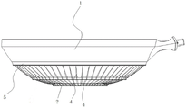
FIG. 1 is a schematic structural view of a magnetic conductive pot body of the present invention;
FIG. 2 is a schematic sectional view of the magnetic conductive pot body of the present invention;
FIG. 3 is an enlarged schematic view at A in FIG. 2;
fig. 4 is a schematic structural view of the magnetic conductive cookware of the present invention from the bottom view;
fig. 5 is a schematic structural view from the bottom view of another embodiment of the magnetic cookware of the present invention.
In the figure: 1. the pot body comprises a pot body 2, supporting ribs 3, a magnetic conduction layer 4, a heat conduction groove 5 and heat resistance ribs.
Detailed Description
The present invention will be further described with reference to the accompanying drawings and embodiments.
As shown in fig. 1-5, the magnetic conductive cookware in the present embodiment includes a pot body 1, wherein the outer wall of the pot body 1 is provided with support ribs 2, and the outer wall of the bottom of the pot body 1 is further sprayed with a magnetic conductive layer 3; the supporting ribs 2 are uniformly arranged around the center of the bottom of the pot body 1, and the magnetic conduction layer 3 is sprayed on the outer wall of the pot body 1 within the range surrounded by the supporting ribs 2. The supporting ribs 2 can be one or more, and can be integrally formed with the pot body 1, and when the supporting ribs 2 are multiple, the magnetic conduction layer 3 is sprayed on the outer wall of the pot body 1 in the maximum range surrounded by the supporting ribs 2.
In the embodiment, the pot body 1 is arranged on the heating platform through the supporting ribs 2, so that a space is still reserved between the bottommost part of the pot body 1 and the heating platform, and unstable placement can not occur even if the bottom of the pot body 1 protrudes outwards when being heated.
The magnetic conduction layer 3 can fix the magnetic conduction material on the outer wall of the pot body 1 within the range surrounded by the support ribs 2 by a thermal spraying method or a cold spraying method, the magnetic conduction material is preferably ferrite steel and is suitable for electromagnetic heating, and the magnetic conduction material can be any appropriate material such as iron. The magnetic conduction layer 3 can also be sprayed outside the surrounding range of the support ribs 2 and on the outer surface of the support ribs 2, which belongs to the same concept, but the effect is smaller, and in order to save the material of the magnetic conduction layer 3, the magnetic conduction layer 3 is preferably sprayed on the outer wall of the pot body 1 within the surrounding range of the support ribs 2, as shown in fig. 3.
The magnetic conduction layer 3 can be completely covered or discontinuously arranged on the outer wall of the pot body 1 enclosed by the support ribs 2, and in order to achieve a good heat conduction effect and simplify the spraying process, the magnetic conduction layer 3 is completely covered and sprayed on the outer wall of the pot body 1 enclosed by the support ribs 2.
The shape of the supporting rib 2 can be round, square or other shapes formed by uniformly surrounding the bottom center of the pot body 1, and the shape of the supporting rib 2 in the embodiment shown in fig. 5 is a petal-like shape formed by uniformly surrounding the bottom center of the pot body 1. In the embodiment, as shown in fig. 1 and 4, the supporting rib 2 is preferably in a ring shape surrounding the center of the bottom of the pot body 1, the pot body 1 is placed more stably by the ring-shaped supporting rib 2, and the pot body 1 is generally in a circular arc shape, and the projection of the pot body on the plane is generally circular and is adapted to the circular supporting rib 2.
The support ribs 2 may be arranged continuously or intermittently, and in this embodiment, the support ribs 2 are preferably arranged continuously to increase the support strength, as shown in fig. 4.
Further, as shown in fig. 1, 4 and 5, the outer wall of the pot body 1 is further provided with a plurality of heat conduction grooves 4, and the plurality of heat conduction grooves 4 are uniformly arranged on the outer wall of the pot body 1 in a radial shape. The radial heat-conducting grooves 4 increase the heat contact area of the outer wall of the pot body 1, greatly increase the heat-conducting property of the pot body 1, save energy consumption and ensure that the pot body 1 is uniformly heated.
Further, as shown in fig. 1, 2, 4 and 5, the outer wall of the pot body 1 is further provided with heat-resistant ribs 5, the heat-resistant ribs 5 are positioned on the outer side of the support ribs 2, and the heat-resistant ribs 5 are uniformly arranged around the center of the bottom of the pot body 1. Hinder hot muscle 5 can with 1 integrated into one piece of pot body, furtherly, hinder hot muscle 5 and be the annular shape around 1 bottom centers of pot body, hinder the vertical distance between the horizontal plane at hot muscle 5 lowest place and the horizontal plane at the bottom of a boiler lowest place not less than 44 mm.
The heat-resistant ribs 5 are vertically arranged downwards, when the open fire is used for boiling, the heat-resistant ribs 5 can effectively insulate heat, the open fire at the bottom of the pot is prevented from being excessively vigorous and being transmitted to the handle of the pot or the edge of the pot body 1, and therefore the risk that a user is scalded is reduced. The heat-resistant ribs 5 can also gather heat at the bottom of the pan, so that the heating efficiency is increased, and the energy consumption is reduced. The vertical distance between the horizontal plane where the lowest part of the heat-resistant rib 5 is located and the horizontal plane where the lowest part of the pan bottom is located is not less than 44mm, and the probability that the heat-resistant rib 5 is collided is reduced.
Furthermore, the projection of the magnetic conduction layer 3 coated on the outer wall of the bottom of the pot body 1 on the horizontal plane is circular, and the diameter of the projection of the magnetic conduction layer 3 on the horizontal plane is not less than 120 mm. When the magnetic conduction layer 3 completely covers the outer wall of the pot body 1 sprayed in the range surrounded by the support ribs 2, the projection of the magnetic conduction layer 3 on the horizontal plane is circular. The technical scheme makes the pot body 1 be heated evenly in the heating process of the induction cooker, and the projection diameter of the magnetic conduction layer 3 on the horizontal plane is not less than 120mm, so that the pot body 1 has a sufficient heating range for cooking food.
Further, the inner wall and the outer wall of the bottom of the pot body 1 are both arc-shaped. Compared with the pan in the prior art, the bottom of the arc-shaped pan body 1 can play a role in gathering oil, and the oil gathering difficulty problem can not occur even if the bottom of the pan is heated and slightly deforms towards the inner wall of the pan body 1 in a protruding manner.
Furthermore, the magnetic conductive cooker of the utility model also comprises a cooker cover matched with the cooker body 1, the cooker cover is provided with a lower concave transparent window, and the cooker cover is provided with a vertical handle; the pan body 1 is also connected with a pan handle.
The lower concave shape is the visual effect of the pot cover when the pot cover is covered on the pot body 1. The lower concave transparent window enables condensed water to be gathered at the center of the transparent window, the amount of the condensed water flowing to the periphery of the pot cover is reduced, the covered edges at the periphery of the pot cover are not easy to dirty in the using process, and the pot cover is convenient to clean. The transparent window can be made of glass and is embedded in the middle of the pot cover.
The vertical lifting handle is fixedly arranged on the pot cover in a screw fixing or riveting mode, enough space is reserved between the vertical lifting handle and the lower concave transparent window for a user to operate the lifting handle to hold the vertical lifting handle, and the pot cover can be conveniently erected on the platform through the vertical lifting handle, so that the probability of pollution to the pot cover is reduced.
In the description of the present invention, it should be noted that, as the terms "center", "upper", "lower", "left", "right", "vertical", "horizontal", "inner", "outer", "concave", "convex", etc. appear, the indicated orientation or positional relationship thereof is based on the orientation or positional relationship shown in the drawings, and is only for convenience of description and simplification of description, and does not indicate or imply that the device or element referred to must have a specific orientation, be constructed and operated in a specific orientation, and thus, should not be construed as limiting the present invention. Furthermore, the terms "first," "second," and "third" as appearing herein are used for descriptive purposes only and are not to be construed as indicating or implying relative importance.
In the description of the present invention, it is to be noted that, unless otherwise explicitly specified or limited, the terms "mounted," "connected," and "connected" should be interpreted broadly, e.g., as being either fixedly connected, detachably connected, or integrally connected; can be mechanically or electrically connected; they may be connected directly or indirectly through intervening media, or they may be interconnected between two elements. The specific meaning of the above terms in the present invention can be understood in specific cases to those skilled in the art.
The same creation is considered to be simply replaced without changing the creation content of the present invention. The embodiments are described in a progressive manner in the specification, each embodiment focuses on differences from other embodiments, and the same and similar parts among the embodiments are referred to each other. The previous description of the disclosed embodiments is provided to enable any person skilled in the art to make or use the present invention. The general principles defined herein may be implemented in other embodiments without departing from the spirit or scope of the invention. Thus, the present invention is not intended to be limited to the embodiments shown herein but is to be accorded the widest scope consistent with the principles and novel features disclosed herein.
Claims (10)
1. A magnetic conduction pan, its characterized in that: the pot comprises a pot body (1), wherein the outer wall of the pot body (1) is provided with a supporting rib (2), and the outer wall of the bottom of the pot body (1) is also sprayed with a magnetic conduction layer (3); the support ribs (2) are uniformly arranged around the center of the bottom of the pot body (1), and the magnetic conduction layer (3) is sprayed on the outer wall of the pot body (1) within the range surrounded by the support ribs (2).
2. The magnetic conductive cookware of claim 1, wherein: the outer wall of the pot body (1) is also provided with a plurality of heat conducting grooves (4).
3. The magnetic conductive cookware of claim 2, wherein: the heat conducting grooves (4) are uniformly arranged on the outer wall of the pot body (1) in a radial shape.
4. The magnetic conductive cookware of claim 1, wherein: the pot body (1) outer wall still is equipped with and hinders hot muscle (5), hinder hot muscle (5) and be located support rib (2) outside.
5. The magnetic conductive cookware of claim 4, wherein: the heat resistance ribs (5) are uniformly arranged around the center of the bottom of the pot body (1), and the vertical distance between the horizontal plane where the lowest part of the heat resistance ribs (5) is located and the horizontal plane where the lowest part of the pot bottom is located is not less than 44 mm.
6. The magnetic conductive cookware of claim 1, wherein: the projection of the magnetic conduction layer (3) coated on the outer wall of the pot body (1) on the horizontal plane is circular.
7. The magnetic conductive cookware of claim 6, wherein: the projection diameter of the magnetic conduction layer (3) on the horizontal plane is not less than 120 mm.
8. The magnetic conductive cookware of claim 7, wherein: the inner wall and the outer wall of the bottom of the pot body (1) are both arc-shaped.
9. A magnetically permeable pot as claimed in any one of claims 1 to 8, wherein: the pot cover is matched with the pot body (1) and is provided with a transparent window which is concave downwards.
10. The magnetic conductive cookware of claim 9, wherein: the pot cover is provided with a vertical handle; or the pot body (1) is provided with a pot handle.
Priority Applications (1)
| Application Number | Priority Date | Filing Date | Title |
|---|---|---|---|
| CN202121002881.2U CN217137474U (en) | 2021-05-10 | 2021-05-10 | Magnetic conduction pan |
Applications Claiming Priority (1)
| Application Number | Priority Date | Filing Date | Title |
|---|---|---|---|
| CN202121002881.2U CN217137474U (en) | 2021-05-10 | 2021-05-10 | Magnetic conduction pan |
Publications (1)
| Publication Number | Publication Date |
|---|---|
| CN217137474U true CN217137474U (en) | 2022-08-09 |
Family
ID=82659321
Family Applications (1)
| Application Number | Title | Priority Date | Filing Date |
|---|---|---|---|
| CN202121002881.2U Active CN217137474U (en) | 2021-05-10 | 2021-05-10 | Magnetic conduction pan |
Country Status (1)
| Country | Link |
|---|---|
| CN (1) | CN217137474U (en) |
-
2021
- 2021-05-10 CN CN202121002881.2U patent/CN217137474U/en active Active
Similar Documents
| Publication | Publication Date | Title |
|---|---|---|
| CN217137474U (en) | Magnetic conduction pan | |
| CN208355196U (en) | A kind of Split electromagnetic lifting chafing dish | |
| CN214700859U (en) | Pot rack and stove | |
| CN201091515Y (en) | Complex stainless steel pot | |
| CN212015282U (en) | Kitchen ware suitable for electromagnetic heating | |
| CN216020530U (en) | Cooking pot | |
| CN205338595U (en) | Multi -purpose pot | |
| CN201775513U (en) | Electromagnetic heating barbeque grill | |
| CN215304918U (en) | Novel cooker | |
| CN218960515U (en) | Ceramic cooker capable of being heated by electromagnetic oven | |
| CN216221168U (en) | Novel energy-saving pot | |
| CN2912446Y (en) | Multipurpose electric cooking stove and pot | |
| CN201303833Y (en) | Wok for induction cooker | |
| CN215604929U (en) | Cooking pot | |
| CN201356422Y (en) | Heat-gathering energy-saving pan | |
| CN220089237U (en) | Synchronous heating type electric heating pot | |
| CN221060358U (en) | Pot tool | |
| CN218304477U (en) | Composite pot | |
| CN215686704U (en) | Pot and cooking utensil | |
| CN218105544U (en) | Cooking pot | |
| CN221577511U (en) | Multifunctional cooking pot | |
| CN218390722U (en) | Frying pan for electromagnetic oven | |
| CN215738366U (en) | Cooking container | |
| CN219645560U (en) | Electric roasting pan with focusing and energy-saving functions | |
| CN216494792U (en) | Energy-saving centrifugal electric heating pot for kitchen |
Legal Events
| Date | Code | Title | Description |
|---|---|---|---|
| GR01 | Patent grant | ||
| GR01 | Patent grant |