CN217134492U - Battery pack and electronic device - Google Patents
Battery pack and electronic device Download PDFInfo
- Publication number
- CN217134492U CN217134492U CN202220645089.7U CN202220645089U CN217134492U CN 217134492 U CN217134492 U CN 217134492U CN 202220645089 U CN202220645089 U CN 202220645089U CN 217134492 U CN217134492 U CN 217134492U
- Authority
- CN
- China
- Prior art keywords
- switch
- electrically connected
- battery
- heater
- cell module
- Prior art date
- Legal status (The legal status is an assumption and is not a legal conclusion. Google has not performed a legal analysis and makes no representation as to the accuracy of the status listed.)
- Active
Links
Images


Landscapes
- Secondary Cells (AREA)
- Charge And Discharge Circuits For Batteries Or The Like (AREA)
Abstract
The embodiment of the application provides a battery pack, a battery heating method and electronic equipment, the battery pack comprises a battery heating circuit, a battery cell module and a heater, the battery heating circuit comprises a controller and a first switch, the first switch comprises an NMOS (N-channel metal oxide semiconductor) tube or a PMOS (P-channel metal oxide semiconductor) tube, the first switch can receive a control signal of the controller to be conducted or cut off, the first switch is electrically connected with the battery cell module and the heater to form a first circuit, the first switch is configured to respond that the temperature of the battery cell module is not lower than a temperature threshold value, the control signal of the controller is received to be conducted, the first circuit is conducted, the temperature of the heater is increased, and the battery cell module is heated. The battery cell module comprises at least one battery cell, the heater comprises at least one sub-heater, the sub-heaters correspond to the battery cells one to one, each sub-heater comprises at least two metal terminals, and the metal terminals are led out from the inside of the battery cells. The scheme can improve the charge and discharge performance of the secondary battery in a low-temperature environment.
Description
Technical Field
The embodiment of the application relates to the technical field of electrical engineering, in particular to a battery pack and electronic equipment.
Background
Secondary batteries, such as lithium ion batteries, sodium ion batteries, and the like, have the advantages of high energy density, long cycle life, high nominal voltage, low self-discharge rate, small volume, light weight, and the like, and are widely used in products such as consumer electronics, unmanned aerial vehicles, and electric vehicles. When the environmental temperature is low, the chemical reaction speed of the secondary battery is low, which affects the normal charge and discharge of the secondary battery, and the discharge of the secondary battery in the low temperature environment is easy to cause irreversible damage to the performance of the secondary battery. Therefore, it is required to provide a technical solution for improving the charge and discharge performance of the secondary battery in a low temperature environment.
SUMMERY OF THE UTILITY MODEL
In view of the above, embodiments of the present disclosure provide a battery pack and an electronic device to improve the charging and discharging performance of a secondary battery in a low temperature environment.
According to a first aspect of embodiments of the present application, there is provided a battery pack including: the battery heating circuit comprises a controller and a first switch, the first switch receives a control signal of the controller to execute switching on or switching off, the first switch comprises an NMOS (N-channel metal oxide semiconductor) tube or a PMOS (P-channel metal oxide semiconductor) tube, and the first switch is electrically connected with the battery core module and the heater. The first switch is configured to respond to the fact that the temperature of the battery cell module is not lower than a temperature threshold value, receive a control signal of the controller and conduct, and a first circuit where the battery cell module, the first switch and the heater are located is conducted to enable the temperature of the heater to rise so as to heat the battery cell module. The battery cell module comprises at least one battery cell, the heater comprises at least one sub-heater, the sub-heaters correspond to the battery cells one to one, each sub-heater comprises at least two metal terminals, and the metal terminals are led out from the inside of the battery cells.
In some embodiments, the control terminal of the first switch is electrically connected to the controller for receiving a control signal of the controller. A first end of the first switch is electrically connected with the positive electrode of the battery cell module, a second end of the first switch is electrically connected with a first end of the heater, and a second end of the heater is electrically connected with the negative electrode of the battery cell module; or the first end of the heater is electrically connected with the positive electrode of the battery cell module, the second end of the heater is electrically connected with the second end of the first switch, and the first end of the first switch is electrically connected with the negative electrode of the battery cell module.
In some embodiments, the battery heating circuit further comprises: the second switch is respectively electrically connected with the heater and the charging port, receives a control signal of the controller and conducts or cuts off the controller. The second switch is configured to receive a control signal of the controller to conduct in response to the temperature of the battery cell module being lower than the temperature threshold, and the charging port is configured to be electrically connected with a charger to conduct a second circuit in which the charger, the second switch and the heater are located.
In some embodiments, a control terminal of the second switch is electrically connected to the controller for receiving a control signal of the controller, and the charging port includes a first charging port and a second charging port. A first end of the second switch is electrically connected with the first charging port, a second end of the second switch is electrically connected with a first end of the heater, and a second end of the heater is electrically connected with the second charging port; or, the first end of the heater is electrically connected to the first charging port, the second end of the heater is electrically connected to the second end of the second switch, and the first end of the second switch is electrically connected to the second charging port.
In some embodiments, when the first switch receives a control signal of the controller to perform on, the second switch receives the control signal of the controller to perform off; or, when the second switch receives the control signal of the controller to execute on, the first switch receives the control signal of the controller to execute off.
In some embodiments, the battery heating circuit further comprises: the detector is respectively electrically connected with the battery cell module and the controller and used for acquiring the temperature information of the battery cell module and sending the temperature information to the controller, and the detector is configured to respond to awakening of the controller and detect the temperature of the battery cell module.
In some embodiments, the controller is configured to wake up in response to a power-on signal entering an active state from a sleep state; or, the charging port is accessed by the charger, and the charging port is awakened by receiving a charging signal.
In some embodiments, the second switch is configured to receive a control signal of the controller to perform the turning off in response to the voltage of the charger being higher than a first voltage threshold.
In some embodiments, the battery heating circuit further comprises: a first diode. The anode of the first diode is electrically connected with the anode of the battery cell module, and the cathode of the first diode is electrically connected with the first switch.
In some embodiments, the battery heating circuit further comprises: a second diode. The anode of the second diode is electrically connected with the charging port, and the cathode of the second diode is electrically connected with the second switch.
In some embodiments, the heater includes more than three sub-heaters, and any one of the following forms of electrical connection is formed between the sub-heaters: (i) the sub-heaters are electrically connected in series; or, (ii) a parallel electrical connection is formed between the sub-heaters; or, (iii) a series-parallel electrical connection is formed between the sub-heaters.
In some embodiments, the battery heating circuit further comprises: a third switch and a fourth switch, the third switch in series with the fourth switch. The third switch and the fourth switch are electrically connected between the positive electrode of the battery cell module and the positive electrode output end of the battery cell module; or the third switch and the fourth switch are electrically connected between the negative electrode of the battery cell module and the negative electrode output end of the battery cell module.
According to a second aspect of embodiments of the present application, there is provided an electronic apparatus including the battery pack of the first aspect described above.
According to the battery heating scheme that this application embodiment provided, when ambient temperature is lower, be not less than the temperature threshold value in response to the temperature of electric core module, the controller can send control signal to first switch, make first switch execution switch on, first switch switches on the back, electric core module, the first circuit at first switch and heater place switches on, be the heater power supply by electric core module, make the heater temperature rise, in order to heat electric core module, make electric core module can rise to suitable temperature in short time, thereby improve the charge-discharge performance of electric core module under low temperature environment.
Drawings
In order to more clearly illustrate the embodiments of the present application or the technical solutions in the prior art, the drawings needed to be used in the description of the embodiments or the prior art will be briefly described below, it is obvious that the drawings in the following description are only some embodiments described in the embodiments of the present application, and other drawings can be obtained by those skilled in the art according to the drawings.
Fig. 1 is a schematic block diagram of a battery pack according to an embodiment of the present application;
FIG. 2 is a schematic diagram of a battery heating circuit according to one embodiment of the present application;
FIG. 3 is a schematic diagram of a battery heating circuit according to another embodiment of the present application;
FIG. 4 is a schematic diagram of a battery heating circuit according to yet another embodiment of the present application;
fig. 5 is a schematic block diagram of a battery pack of another embodiment of the present application;
fig. 6 is a schematic block diagram of a battery pack of yet another embodiment of the present application;
fig. 7 is a schematic diagram of a cell of an embodiment of the present application;
figure 8 is a schematic view of a heat patch according to one embodiment of the present application.
Detailed Description
In order to make those skilled in the art better understand the technical solutions in the embodiments of the present application, the technical solutions in the embodiments of the present application will be described clearly and completely below with reference to the drawings in the embodiments of the present application, and it is obvious that the described embodiments are only a part of the embodiments of the present application, but not all embodiments. All other embodiments obtained by a person of ordinary skill in the art based on the embodiments in the present application shall fall within the scope of the protection of the embodiments in the present application.
Specific implementations of embodiments of the present application are further described below with reference to the accompanying drawings.
A secondary battery is a rechargeable battery that operates by moving metal ions, such as lithium ions and sodium ions, between a positive electrode and a negative electrode, and is widely used in consumer electronics, unmanned aerial vehicles, electric vehicles, and the like. The working principle of the secondary battery is that the electrolyte inside the secondary battery generates potential difference at the positive electrode and the negative electrode through the change of chemical reaction, so that current is generated. The moving speed of the electrolyte becomes slow under a low-temperature environment, so that the transfer activity of metal ions between a positive electrode and a negative electrode is influenced, and the charge and discharge performance of the battery is reduced. And the secondary battery is easily damaged by discharging in a low-temperature environment. Therefore, there is a need for a solution for increasing the temperature of a secondary battery, which can heat the secondary battery at a low temperature to improve the charge and discharge performance of the secondary battery at a low temperature.
Battery pack
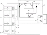
Fig. 1 is a schematic block diagram of a battery pack according to an embodiment of the present application. As shown in fig. 1, the battery pack 100 includes a battery heating circuit 10, a battery cell module 20, and a heater 30, the battery heating circuit 10 includes a controller 11 and a first switch 12, the first switch 12 is a controllable switch and can receive a control signal from the controller 11 to perform on or off, and the first switch 12 can be an NMOS transistor or a PMOS transistor. The first switch 12 is electrically connected to the cell module 20 and the heater 30. First switch 12 is not less than the temperature threshold value in response to the temperature of electric core module 20, can receive controller 11's control signal execution to switch on, makes the first circuit at electric core module 20, first switch 12 and heater 30 place switch on, and then makes heater 30's temperature rise to heat electric core module 20.
In this application embodiment, when ambient temperature is lower, be not less than the temperature threshold value in response to electric core module 20's temperature, controller 11 can send control signal to first switch 12, make first switch 12 execute and switch on, first switch 12 switches on the back, electric core module 20, the first circuit at first switch 12 and heater 30 place switches on, be heater 30 power supply by electric core module 20, make heater 30 temperature rise, heat electric core module 20, make electric core module 20 can rise to suitable temperature in short time, thereby improve electric core module 20 charge and discharge performance under low temperature environment.
It should be understood that the Battery pack 100 may include a cell module, a heater, and a Battery Management System (BMS), and the Battery heating circuit 10 may be disposed on the BMS, which may be in the form of a circuit board in a specific implementation, and may manage charging and discharging of the cell module.
It should also be understood that the controller 11 may be disposed on the BMS circuit board, and in response to the temperature of the cell module 20 not being lower than the temperature threshold, send a control signal to the first switch 12, which means that the controller can obtain the temperature information of the cell module 20 or the temperature information of the environment where the cell module 20 is located, when the temperature of the cell module 20 is low enough to affect normal charging and discharging, but the temperature of the cell module 20 is not lower than the temperature threshold, the controller 11 may send a control signal to the first switch 12, so that the first switch 12 is turned on, and the cell module 20 supplies power to the heater 30, so that the heater 30 heats the cell module 20. In one of the implementation manners, after the temperature of the battery cell module 20 is lower than 0 ℃, for example, the temperature of the battery cell module 20 is-15 ℃, or the ambient temperature of the battery pack 100 is-15 ℃, the low temperature may have a large influence on the charging and discharging performance of the battery cell module 20, and the temperature threshold is-20 ℃, so that when the temperature of the battery cell module 20 is in the range from-20 ℃ to 0 ℃, the battery cell module 20 may send a control signal to the first switch 12, so that the first switch 12 is turned on.
When the temperature of electric core module 20 is higher, need not to heat electric core module 20, so low when influencing electric core module 20 normal charge-discharge of temperature at electric core module 20, controller 11 can send control signal to first switch 12. When the temperature at battery core module 20 is less than the temperature threshold value, the discharge of battery core module 20 can be closed to the BMS circuit board, because if battery core module 20 discharges under the temperature that is less than the temperature threshold value, can cause irreversible harm for the performance of the electric core that battery core module 20 includes, so after the temperature at battery core module 20 is less than the temperature threshold value (for example-20 ℃), controller 11 can not send control signal to first switch 12, first switch 12 is in the off-state, battery core module 20 no longer supplies power to heater 30.
Fig. 2 to 4 are schematic diagrams of three battery heating circuits provided in the embodiment of the present application. As shown in fig. 2 to 4, a control terminal of the first switch 12 is electrically connected to the controller 11, and the first switch 12 receives a control signal of the controller 11 through the control terminal. As shown in fig. 2 and 3, a first end of the first switch 12 is electrically connected to the positive electrode of the cell module 20, a second end of the first switch 12 is electrically connected to a first end of the heater 30, and a second end of the heater 30 is electrically connected to the negative electrode of the cell module 20. As shown in fig. 4, a first end of the heater 30 is electrically connected to the positive electrode of the cell module 20, a second end of the heater 30 is electrically connected to the second end of the first switch 12, and a first end of the first switch 12 is electrically connected to the negative electrode of the cell module 20.
The control end of the first switch 12 is electrically connected to the controller 11, and the controller 11 may send a control signal to the control end of the first switch 12, so that the first switch 12 is turned on or off, and a first circuit where the cell module 20, the first switch 12 and the heater 30 are located is turned on or off, so as to start heating the cell module 20, or stop heating the cell module 20. As shown in fig. 2 and 3, when the controller 11 controls the positive electrode of the cell module 20, the first switch 12 is electrically connected between the positive electrode of the cell module 20 and the heater 30, and as shown in fig. 4, when the controller 11 controls the negative electrode of the cell module 20, the first switch 12 is electrically connected between the heater 30 and the negative electrode of the cell module 20.
In an embodiment of the present application, a control end of the first switch 12 is electrically connected to the controller 11, and the first switch 12 may be electrically connected between an anode of the cell module 20 and the heater 30, so as to control the anode of the cell module 20. In another embodiment of the present application, the first switch 12 may also be electrically connected between the heater 30 and the negative electrode of the cell module 20, so as to control the negative electrode of the cell module 20. The controller 11 can control the positive pole or the negative pole of the battery core module 20, and controls the on and off of the first switch 12, so that the battery management system is suitable for positive pole control and negative pole control, and the applicability of the battery heating circuit provided by the embodiment of the application is improved.
In the embodiment of the present application, the first switch 12 may be a controllable switch including a control terminal, an input terminal, and an output terminal, for example, the first switch 12 may be a transistor, a PMOS transistor, or an NMOS transistor. When the first switch 12 is a MOS transistor (PMOS transistor or NMOS transistor), the first switch 12 shown in fig. 2 and 3 is a PMOS transistor, and the first switch 12 shown in fig. 4 is an NMOS transistor. The gate of the MOS transistor is the control end of the first switch 12, the source of the MOS transistor is the first end of the first switch 12, and the drain of the MOS transistor is the second end of the first switch 12.
Fig. 5 is a schematic block diagram of a battery heating circuit provided in another embodiment of the present application. As shown in fig. 5, the battery heating circuit 10 includes a second switch 13 and a charging port 14 in addition to the controller 11 and the first switch 12. The charging port 14 may be electrically connected to a charger 40. The second switch 13 is electrically connected to the heater 30 and the charging port 14, respectively, and the second switch 13 is a controllable switch, and may receive a control signal from the controller 11 and perform on or off based on the received control signal. In response to the temperature of the cell module 20 being lower than the temperature threshold (for example, -20 ℃), the second switch 13 receives the control signal of the controller 11 to perform conduction, so that the second circuit in which the charger 40, the second switch 13, and the heater 30 are located is conducted, and the temperature of the heater 30 is increased, so as to heat the cell module 20.
In this application embodiment, when the temperature of battery cell module 20 is less than the temperature threshold value, the BMS circuit board can turn off the discharge switch, avoids battery cell module 20 to discharge, because battery cell module 20 continues to discharge under the environment that is less than the temperature threshold value, may cause irreversible damage to the performance of battery cell module 20, and battery cell module 20 no longer supplies power for heater 30 this moment. After the charger 40 accesses the battery pack through the charging port 14, the controller 11 can respond to a charging handshake signal sent by the charger 40, and can send a control signal to the second switch 13, so that the second switch 13 is turned on, after the second switch 13 is turned on, a second circuit where the charger 40, the second switch 13 and the heater 30 are located is turned on, the charger 40 supplies power to the heater 30, so that the temperature of the heater 30 is increased to heat the battery cell module 20, and further, the battery cell module 20 can be raised to an appropriate temperature in a short time, so that the charging and discharging performance of the battery cell module 20 in a low-temperature environment is improved.
When the temperature of the battery cell module 20 is lower than the temperature threshold value (for example, -20 ℃), the BMS circuit board controls the battery cell module 20 not to discharge, and therefore the heater 30 cannot be powered through the battery cell module 20, the charger 40 is electrically connected to the charging port 14 at the moment, the controller 11 controls the second switch 13 to be switched on, the charger 40 supplies power to the heater 30, the temperature of the heater 30 is increased, after the battery cell module 20 is heated, the battery cell module 20 is controlled by the BMS circuit board to normally charge and discharge after the temperature of the battery cell module 20 is increased to a proper temperature.
In one implementation of the present application, as shown in fig. 3, a control terminal of the second switch 13 is electrically connected to the controller 11, the control terminal of the second switch 13 can receive a control signal of the controller 11, and the charging port 14 includes a first charging port C + and a second charging port C-. As shown in fig. 3, a first terminal of the second switch 13 is electrically connected to the first charging port C +, a second terminal of the second switch 13 is electrically connected to a first terminal of the heater 30, and a second terminal of the heater 30 is electrically connected to the second charging port C-. In another implementation of the present application, as shown in fig. 4, a first terminal of the heater 30 is electrically connected to the first charging port C +, a second terminal of the heater 30 is electrically connected to a second terminal of the second switch 13, and a first terminal of the second switch 13 is electrically connected to the second charging port C-.
The control end of the second switch 13 is electrically connected to the controller 11, and the controller 11 may send a control signal to the control end of the second switch 13 to turn on or off the second switch 13, so as to turn on or off a second circuit where the charger 40, the second switch 13, and the heater 30 are located, so that the charger 40 starts or stops supplying power to the heater 30, and further starts or stops heating the battery cell module 20. When the controller 11 controls the positive electrode of the cell module 20, the second switch 13 is electrically connected between the first charging port C + and the heater 30. When the controller 11 controls the negative electrode of the battery cell module 20, the second switch 13 is electrically connected between the heater 30 and the second charging port C-.
In an embodiment of the application, a control end of the second switch 13 is electrically connected to the controller 11, and the second switch 13 may be electrically connected between the first charging port C + and the heater 30, so as to control the positive electrode of the cell module 20. In another embodiment of the present application, the second switch 13 may be electrically connected between the heater 30 and the second charging port C-, so as to control the negative electrode of the cell module 20. The controller 11 can control the positive pole or the negative pole of the battery core module 20, and controls the on and off of the second switch 13, so that the battery management system is suitable for the positive pole control and the negative pole control, and the applicability of the battery heating circuit provided by the embodiment of the application is improved.
In the embodiment of the present application, the second switch 13 may be a controllable switch including a control terminal, an input terminal, and an output terminal, for example, the second switch 13 may be a transistor, a PMOS transistor, or an NMOS transistor. When the second switch 13 is a MOS transistor (a PMOS transistor or an NMOS transistor), the second switch 13 shown in fig. 3 is a PMOS transistor, the second switch 13 shown in fig. 4 is an NMOS transistor, a gate of the MOS transistor is a control terminal of the second switch 13, a source of the MOS transistor is a first terminal of the second switch 13, and a drain of the MOS transistor is a second terminal of the second switch 13.
Fig. 6 is a schematic block diagram of a battery heating circuit provided in another embodiment of the present application. As shown in fig. 6, the battery heating circuit 10 further includes a detector 15. The detector 15 is electrically connected to the cell module 20 and the controller 11, and the detector 15 may acquire temperature information of the cell module 20 and send the temperature information to the controller 11. In response to the controller 11 waking up, the detector 15 may detect the temperature of the cell module 20.
In this embodiment of the application, the controller 11 is awakened from the sleep mode, and after entering the operating mode, the controller 11 may send a control signal to the detector 15, so that the detector 15 detects the temperature of the battery cell module 20, obtain temperature information used for indicating the temperature of the battery cell module 20, and send the obtained temperature information to the controller 11, and then the controller 11 may control the on/off of the first switch 12 and/or the second switch 13 according to the temperature information, so as to heat the battery cell module 20 when the temperature of the battery cell module 20 is lower. When the controller 11 is in the sleep mode, the detector 15 does not detect the temperature of the cell module 20, so as to reduce the power consumption of the battery pack 100. Awaken up the back at controller 11, and battery module 20 begins the charge-discharge work, and detector 15 detects the temperature of battery module 20 to in time heat battery module 20 when battery module 20 temperature is lower, guarantee that battery module 20 can carry out normal charge-discharge state fast.
It should be understood that the awake state of the controller 11 may represent that the BMS circuit board is in an operating state, and the non-awake state of the controller 11 may represent that the BMS circuit board is in a low power consumption state, including but not limited to a sleep state, a standby state, a power-off state, etc. Specifically, when the BMS circuit board is in a low power consumption state, the partial circuits are not used, and accordingly, the controller 11 is in a non-wake-up state accordingly, and the power supply of the partial circuits, such as the power supply of the disconnection detector 15, is disconnected, achieving low power consumption of the battery pack 100.
In one example, the detector 15 may be a temperature sensor disposed on the surface of the battery cell module 20, or may be an Analog Front End (AFE) chip disposed on the BMS circuit board.
In one implementation, the wake-up of the controller 11 includes multiple forms, such as the controller 11 entering the active state from the sleep state in response to a power-on signal of an electronic device (e.g., a motorcycle, a drone, a power tool, etc.), and the controller 11 being woken up, or the controller 11 receiving a charging signal and the controller 11 being woken up in response to the charger 40 accessing the charging port 14.
The controller 11 receives a power-on signal triggered by a user through a power-on key or the like, and the controller 11 is awakened after receiving the power-on signal, so that the controller 11 obtains temperature information of the detector 15, so as to turn on a power supply circuit of the heater 30 when the temperature of the battery cell module 20 is low, and heat the battery cell module 20 through the heater 30, so that the battery cell module 20 is at a proper temperature. After the charger 40 is connected to the charging port 14, the controller 11 may receive a charging handshake signal sent by the charger 40 to wake up, and then the controller 11 obtains temperature information of the detector 15, so as to turn on a power supply line of the heater 30 when the temperature of the cell module 20 is low, and heat the cell module 20 through the heater 30, so that the cell module 20 is at a suitable temperature.
In this embodiment of the application, the controller 11 wakes up after receiving the start signal or the charging signal, the controller 11 after waking up can control the detector 15 to detect the temperature of the battery core module 20, and then the power supply line of the heater 30 is switched on when the temperature of the battery core module 20 is lower, heat the battery core module 20 through the heater 30, make the battery core module 20 normally charge or discharge, both can guarantee that the battery core module 20 can normally charge and discharge under the low temperature environment, can also reduce the consumption of the battery heating circuit 10.
In one implementation, the second switch 13 receives a control signal of the controller 11 to perform the turn-off in response to the voltage of the charger 40 being higher than the first voltage threshold.
In this embodiment of the application, as shown in fig. 3 or fig. 4, after the second switch 13 is turned on, the charger 40 supplies power to the heater 30, the controller 11 obtains a voltage between the first charging port C + and the second charging port C-, where the voltage is an output voltage of the charger 40, and if the controller 11 determines that the voltage is higher than a first voltage threshold, the controller sends a control signal to the second switch 13 to turn off the second switch 13, so that the heater 30 is prevented from being burned out, and safety of heating the cell module 20 is ensured. In one specific embodiment, the first voltage threshold may be a rated voltage of the cell module 20, and in another optional embodiment, the first voltage threshold is greater than the rated voltage of the cell module 20, for example, 5V, 10V, or 15V greater than the rated voltage of the cell module 20. The specific value of the first voltage threshold is merely an example, and does not constitute a limitation on the first voltage threshold.
In one implementation, as shown in fig. 2 to 4, the battery heating circuit 10 further includes a first diode 16, an anode of the first diode 16 is electrically connected to an anode of the cell module 20, and a cathode of the first diode 16 is electrically connected to the first switch 12.
Specifically, in the battery heating circuit 10 shown in fig. 2 and 3, the anode of the first diode 16 is electrically connected to the anode of the cell module 20, and the cathode of the first diode 16 is electrically connected to the first terminal of the first switch 12. In the battery heating circuit 10 shown in fig. 4, the positive electrode of the cell module 20 is electrically connected to the first end of the heater 30, the second end of the heater 30 is electrically connected to the positive electrode of the first diode 16, that is, the positive electrode of the first diode 16 is indirectly electrically connected to the positive electrode of the cell module 20 through the heater 30, and the negative electrode of the first diode 16 is electrically connected to the second end of the first switch 12.
In this embodiment of the application, the anode of the first diode 16 is electrically connected to the anode of the battery module 20, and the cathode of the first diode 16 is electrically connected to the first switch 12, so that the current in the first circuit can only flow to the first switch 12 from the battery module 20 and cannot flow to the battery module 20 from the first switch 12 based on the unidirectional conductive performance of the diode, thereby avoiding the occurrence of short circuit and other faults, and ensuring the safety of the battery heating circuit 10 and the battery management system.
In one implementation, as shown in fig. 3 and 4, the battery heating circuit 10 further includes a second diode 17, an anode of the second diode 17 is electrically connected to the charging port 14, and a cathode of the second diode 17 is electrically connected to the second switch 13.
Specifically, in the battery heating circuit 10 shown in fig. 3, the anode of the second diode 17 is electrically connected to the first charging port C +, and the cathode of the second diode 17 is electrically connected to the first terminal of the second switch 13. In the battery heating circuit 10 shown in fig. 4, a first terminal of the heater 30 is electrically connected to the first charging port C +, a second terminal of the heater 30 is electrically connected to an anode of the second diode 17, and a cathode of the second diode 17 is electrically connected to a second terminal of the second switch 13.
In the embodiment of the present application, the anode of the second diode 17 is electrically connected to the charging port 14, and the cathode of the second diode 17 is electrically connected to the second switch 13, so that based on the unidirectional conductivity of the diodes, the current in the second circuit can only flow from the charger 40 to the second switch 13, but cannot flow from the second switch 13 to the charger 40, thereby avoiding the occurrence of short circuit and other faults, and ensuring the safety of the battery heating circuit 10 and the battery management system.
In one implementation, as shown in fig. 2 to 4, the battery heating circuit 10 further includes a third switch 18 and a fourth switch 19, and the third switch 18 and the fourth switch 19 are connected in series. As shown in fig. 2 and 3, the third switch 18 and the fourth switch 19 may be electrically connected between the positive electrode of the cell module 20 and the positive electrode output end P + of the cell module 20. As shown in fig. 4, the third switch 18 and the fourth switch 19 may also be electrically connected between the negative electrode of the cell module 20 and the negative output terminal P "of the cell module 20.
In this embodiment, the third switch 18 and the fourth switch 19 are controllable switches disposed on the BMS circuit board and used for controlling charging and discharging of the cell module 20, control terminals of the third switch 18 and the fourth switch 19 are both electrically connected to the controller 11, and the controller 11 sends control signals to the third switch 18 and the fourth switch 19 to turn on or off the third switch 18 and the fourth switch 19, so as to control charging and discharging of the cell module 20. The circuit that third switch 18 and fourth switch 19 were located and the circuit that first switch 12 and/or second switch 13 were located are parallelly connected in parallel for when third switch 18 and fourth switch 19 all turn off, first switch 12 or second switch 13 switch on the back, still can heat electric core module 20, thereby can preheat electric core module 20 before electric core module 20 charges or discharges, guarantee that electric core module 20 can normally charge and discharge under low temperature environment, can also improve electric core module 20's life.
In one implementation, the third switch 18 and the fourth switch 19 may be power transistors, such as NMOS transistors in the battery heating circuit 10 shown in fig. 2 to 4.
In the embodiment of the present application, it is described that the charging port and the discharging port of the battery cell module 20 are the same port, that is, the first charging switch C + can be used as the positive output terminal P + of the battery cell module 20, and the second charging port C-can be used as the negative output terminal P-of the battery cell module 20, when an actual service is implemented, the charging port and the discharging port of the battery cell module 20 may be the same port or different ports, which is not limited in the embodiment of the present application.
The operation of the battery heating circuit 10 shown in fig. 2 to 4 will be described in detail.
As shown in fig. 2, in response to that the temperature of the battery cell module 20 is not lower than the preset temperature threshold, the controller 11 sends a control signal to the first switch 12, so that the first switch 12 is turned on. If the charger 40 does not access the charging port 14, after the first switch 12 is turned on, the circuit where the cell module 20, the first diode 16, the first switch 12 and the heater 30 are located is turned on, and the cell module 20 supplies power to the heater 30, so that the temperature of the heater 30 is increased to heat the cell module 20. If the charger 40 is connected to the charging port 14, and after the first switch 12 is turned on, based on the one-way conductivity of the first diode 16 and the second diode 17, if the output voltage of the cell module 20 is greater than the output voltage of the charger 40, the circuit where the cell module 20, the first diode 16, the first switch 12, and the heater 30 are located is turned on, the cell module 20 supplies power to the heater 30, so that the temperature of the heater 30 is increased to heat the cell module 20, and if the output voltage of the cell module 20 is less than the output voltage of the charger 40, the circuit where the charger 40, the second diode 17, the first switch 12, and the heater 30 are located is turned on, and the charger 40 supplies power to the heater 30, so that the temperature of the heater 30 is increased to heat the cell module 20.
As shown in fig. 3 and 4, in response to that the temperature of the battery cell module 20 is not lower than the preset temperature threshold, the controller 11 sends a control signal to the first switch 12, so that the first switch 12 is turned on, while the second switch 13 is kept off, after the first switch 12 is turned on, a circuit where the battery cell module 20, the first diode 16, the first switch 12 and the heater 30 are located is turned on, the battery cell module 20 supplies power to the heater 30, and the temperature of the heater 30 is raised, so as to heat the battery cell module 20. In response to the fact that when the charger 40 is connected to the charging port 14, the controller 11 obtains the temperature of the cell module 20, if the temperature of the cell module 20 is lower than a preset temperature threshold, the controller 11 sends a control signal to the second switch 13 to turn on the second switch 13, while the first switch 12 is kept off, after the second switch 13 is turned on, a circuit where the charger 40, the second diode 17, the second switch 13 and the heater 30 are located is turned on, and the charger 40 supplies power to the heater 30 to raise the temperature of the heater 30, so as to heat the cell module 20.
As shown in fig. 3 and 4, the first switch 12 is connected in series with the first diode 16, and the second switch 13 is connected in series with the second diode 17, when a logic error occurs in the controller 11, for example, a control signal sent by the controller 11 turns on both the first switch 12 and the second switch 13, based on the unidirectional conductive performance of the first diode 16 and the second diode 17, a short circuit can be prevented from occurring in the case that the third switch 18 and the fourth switch 19 are not closed, and the first switch 12 and the second switch 13 are prevented from being burned.
The second diode 17 may be a schottky diode. Since the schottky diode has an overcurrent protection function, when the charger 40 has an overcurrent fault, that is, the output current of the charger 40 is greater than a set value, the second diode 17 (schottky diode) is fused to protect the second switch 13 and the heater 30. When the second diode 17 is a schottky diode, the battery heating circuit 10 does not need an additional fuse based on the overcurrent protection effect of the schottky diode, and the battery heating circuit 10 is ensured to have lower cost.
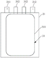
In one implementation, as shown in fig. 2 to 4, the cell module 20 includes at least one cell 21, and the heater 30 includes at least one sub-heater 31. The sub-heaters 31 correspond to the battery cells 21 one by one, and each sub-heater 31 includes at least two metal terminals, and the metal terminals are led out from the inside of the battery cell 21.
In the embodiment of the present application, the battery cell module 20 includes one or more battery cells 21, and a sub-heater 31 is provided in each battery cell 21, and the sub-heater 31 generates heat after being powered on, so as to heat the battery cell 21, and the temperature of the battery cell 21 can be increased more quickly.
Fig. 7 is a schematic diagram of a battery cell 21 provided in an embodiment of the present application, and fig. 8 is a schematic diagram of a sub-heater 31 provided in an embodiment of the present application. As shown in fig. 7 and 8, the sub-heater 31 includes a heating plate 311 and a metal terminal 312, the heating plate 311 is electrically connected to the metal terminal 312, the heating plate 311 is disposed inside the battery cell 21, and the metal terminal 312 is led out from the inside of the battery cell 21, so as to facilitate the electrical connection between the sub-heater 31 and the electrical connection between the heater 30 and the battery heating circuit 10 and the battery cell module 20. The battery cell 21 further includes a positive terminal 211 and a negative terminal 212.
As shown in fig. 8, the heating plate 311 has a plate-shaped serpentine structure, and the material of the heating plate 311 may be copper, aluminum or nickel.
When the ambient temperature is-20 ℃, the heating current is 6A to supply power to the heating sheet 311 for 240s, the surface temperature rise rate of the battery cell adopting the copper heating sheet is 2.4 ℃/min, the surface temperature rise rate of the battery cell adopting the aluminum heating sheet is 4.0 ℃/min, and the surface temperature rise rate of the battery cell adopting the nickel heating sheet is 6.6 ℃/min.
In one implementation, the battery cell 21 includes a positive electrode, a negative electrode, and a diaphragm located between the positive electrode and the negative electrode, the positive electrode-diaphragm-negative electrode stack is wound on the heating sheet 311, the heating sheet 311 is wound inside the battery cell 21, and when the heating sheet 311 is energized to generate heat, the temperature of the battery cell 21 can be increased more quickly.
The following table 1 shows the heating effect data of the two kinds of heating sheets with respect to the comparative example.
TABLE 1
| Heating plate 1 | Heating plate 2 | Comparative example | |
| Heating plate position | Embedded electric core | Embedded electric core | Wound outside the battery cell |
| Heating sheet resistance (omega) | 13.8 | 13.2 | 15.2 |
| Heating current (A) | 2.9 | 5.5 | 1.8 |
| Heating power (W) | 116.1 | 399.3 | 49.2 |
| Heating speed (. degree. C./min) | 11.7 | 34.8 | 3.5 |
| Temperature uniformity | ☆☆☆ | ☆☆ | ☆☆ |
In the heating sheet 1, the heating sheet 2 and the comparative example shown in the above table 1, the weight of each heating sheet is less than 0.45g, the weight of the cell is 92g, the energy density loss (GED loss) of the cell in which each heating sheet is located is less than or equal to 0.5%, the thickness of the heating sheet 1 and the heating sheet 2 is less than 50 μm, and the thickness of the heating sheet in the comparative example is less than 0.5 mm. In the temperature uniformity index of table 1, it is supposed that the more the temperature uniformity of the surface of the cell module is indicated, the better the temperature uniformity of the surface of the cell module is.
Through the comparison of the heating effect data of the heating sheet 1, the heating sheet 2 and the comparative example in the table 1, the heating sheet is arranged inside the battery core, and when the battery core is heated through the heating sheet, the temperature rise speed of the battery core can be improved.
In one implementation, the heater 30 includes at least three sub-heaters 31, and any one of the following electrical connections is formed between the sub-heaters 31:
(i) the sub-heaters 31 are electrically connected in series;
(ii) the sub-heaters 31 are electrically connected in parallel;
(iii) the sub-heaters 31 are electrically connected in series and parallel.
The formation of the series-parallel electrical connection between the sub-heaters 31 means that the first part of the sub-heaters 31 are electrically connected in series, the remaining part of the sub-heaters 31 are electrically connected in series, and the first part of the sub-heaters 31 are electrically connected in parallel with the remaining part of the sub-heaters 31. As shown in fig. 2 and 3, the sub-heaters 31 are electrically connected in series and parallel. As shown in fig. 4, the sub-heaters 31 are electrically connected in series.
In the embodiment of the present application, when the sub-heaters 31 are electrically connected in parallel or in series and parallel, the total resistance of the heater 30 may be reduced, so that the heating current input to each sub-heater 31 may be increased on the premise that the input voltage is not changed, and the temperature of the battery cell 21 may be increased by each sub-heater 31, thereby increasing the heating effect on the battery cell module 20.
The sub-heaters 31 are arranged inside the battery cell 21, the sub-heaters 31 are electrically connected in a parallel-serial manner, and a distributed power supply manner can be adopted to supply power to the sub-heaters 31, so that the flexibility of supplying power to the heaters 31 is ensured.
Electronic device
An embodiment of the present application provides an electronic device, including the battery pack in the above embodiment. Electronic equipment can be unmanned aerial vehicle, electronic two wheeler, electric tool etc. when electronic equipment used under the low temperature environment, through electric core module or the charger in the battery package, for the heater power supply in the battery package, in order to heat the electric core module through the heater, make the electric core module can rise to suitable temperature in the short time, thereby improve the charge-discharge performance of electric core module under low temperature environment, promote electronic equipment and experience in the use under low temperature environment.
It should be noted that, since the heating circuit of the cell module has been described in detail in the foregoing embodiment of the battery pack, the heating principle of the cell module in the electronic device may refer to the description in the foregoing embodiment, and is not described again here.
Commercial value of embodiments of the present application
The embodiment of the application is relatively poor in secondary battery charge and discharge performance under solving low temperature environment, and during the technical problem that leads to secondary battery to damage easily, when ambient temperature is lower, be not less than the temperature threshold value in response to the temperature of electric core module, the controller can send control signal to first switch, make first switch execution switch on, first switch switches on the back, electric core module, the first circuit at first switch and heater place switches on, be the heater power supply by electric core module, make the heater temperature rise, in order to heat electric core module, make electric core module can rise to suitable temperature in short time, thereby improve the charge and discharge performance of electric core module under low temperature environment.
It should be understood that the embodiments in this specification are described in a progressive manner, and that the same or similar parts in the various embodiments may be referred to one another, with each embodiment being described with emphasis instead of the other embodiments. In particular, as for the method embodiments, since they are substantially similar to the methods described in the apparatus and system embodiments, the description is simple, and the relevant points can be referred to the partial description of the other embodiments.
It should be understood that the above description describes particular embodiments of the present specification. Other embodiments are within the scope of the following claims. In some cases, the actions or steps recited in the claims may be performed in a different order than in the embodiments and still achieve desirable results. In addition, the processes depicted in the accompanying figures do not necessarily require the particular order shown, or sequential order, to achieve desirable results. In some embodiments, multitasking and parallel processing may also be possible or may be advantageous.
It should be understood that an element described herein in the singular or shown in the figures only represents that the element is limited in number to one. Furthermore, modules or elements described or illustrated herein as separate may be combined into a single module or element, and modules or elements described or illustrated herein as single may be split into multiple modules or elements.
It is also to be understood that the terms and expressions employed herein are used as terms of description and not of limitation, and that the embodiment or embodiments of the specification are not limited to those terms and expressions. The use of such terms and expressions is not intended to exclude any equivalents of the features shown and described (or portions thereof), and it is recognized that various modifications may be made within the scope of the claims. Other modifications, variations, and alternatives are also possible. Accordingly, the claims should be looked to in order to cover all such equivalents.
Claims (13)
1. A battery pack, comprising: the battery heating circuit comprises a controller and a first switch, the first switch receives a control signal of the controller to execute on or off, and the first switch comprises an NMOS (N-channel metal oxide semiconductor) tube or a PMOS (P-channel metal oxide semiconductor) tube;
the first switch is electrically connected with the battery cell module and the heater;
the first switch is configured to respond that the temperature of the battery cell module is not lower than a temperature threshold value, receive a control signal of the controller and conduct, and a first circuit where the battery cell module, the first switch and the heater are located is conducted to enable the temperature of the heater to rise so as to heat the battery cell module; the cell module comprises at least one cell, and the heater comprises at least one sub-heater;
the sub-heaters correspond to the battery cells one to one, each sub-heater comprises at least two metal terminals, and the metal terminals are led out from the interior of the battery cells.
2. The battery pack according to claim 1, wherein a control terminal of the first switch is electrically connected to the controller for receiving a control signal of the controller;
a first end of the first switch is electrically connected with the positive electrode of the battery cell module, a second end of the first switch is electrically connected with a first end of the heater, and a second end of the heater is electrically connected with the negative electrode of the battery cell module;
or the first end of the heater is electrically connected with the positive electrode of the battery cell module, the second end of the heater is electrically connected with the second end of the first switch, and the first end of the first switch is electrically connected with the negative electrode of the battery cell module.
3. The battery pack of claim 1, wherein the battery heating circuit further comprises: the second switch is electrically connected with the heater and the charging port respectively, receives a control signal of the controller and executes on or off;
the second switch is configured to receive a control signal of the controller to conduct in response to the temperature of the battery cell module being lower than the temperature threshold, and the charging port is configured to be electrically connected with a charger to conduct a second circuit in which the charger, the second switch and the heater are located.
4. The battery pack of claim 3, wherein the control terminal of the second switch is electrically connected to the controller for receiving a control signal from the controller, and the charging port comprises a first charging port and a second charging port;
a first end of the second switch is electrically connected with the first charging port, a second end of the second switch is electrically connected with a first end of the heater, and a second end of the heater is electrically connected with the second charging port;
or, the first end of the heater is electrically connected to the first charging port, the second end of the heater is electrically connected to the second end of the second switch, and the first end of the second switch is electrically connected to the second charging port.
5. The battery pack according to claim 3, wherein the second switch receives the control signal of the controller to turn off when the first switch receives the control signal of the controller to turn on;
or, when the second switch receives the control signal of the controller to execute on, the first switch receives the control signal of the controller to execute off.
6. The battery pack of any of claims 3-5, wherein the battery heating circuit further comprises: the detector is respectively electrically connected with the battery cell module and the controller and is used for acquiring temperature information of the battery cell module and sending the temperature information to the controller;
wherein, in response to the controller waking up, the detector detects the temperature of the cell module.
7. The battery pack of claim 6, wherein the controller wake-up further comprises:
responding to a starting signal, enabling the controller to enter a working state from a dormant state, and waking up the controller;
or, in response to the charger being connected to the charging port, the controller receives a charging signal and the controller wakes up.
8. The battery pack according to any one of claims 3 to 5, wherein the second switch receives a control signal of the controller to perform turn-off in response to the voltage of the charger being higher than a first voltage threshold.
9. The battery pack of any of claims 1-5, wherein the battery heating circuit further comprises: a first diode;
the anode of the first diode is electrically connected with the anode of the battery cell module, and the cathode of the first diode is electrically connected with the first switch.
10. The battery pack of any of claims 3-5, wherein the battery heating circuit further comprises: a second diode;
the anode of the second diode is electrically connected with the charging port, and the cathode of the second diode is electrically connected with the second switch.
11. The battery pack according to claim 1, wherein the heater includes three or more sub-heaters, and any one of the following electrical connections is formed between the sub-heaters:
(i) the sub-heaters are electrically connected in series;
(ii) the sub-heaters are electrically connected in parallel;
(iii) and the sub-heaters are electrically connected in series and parallel.
12. The battery pack of any of claims 1-5, wherein the battery heating circuit further comprises: a third switch and a fourth switch, the third switch in series with the fourth switch;
the third switch and the fourth switch are electrically connected between the positive electrode of the battery cell module and the positive electrode output end of the battery cell module;
or the third switch and the fourth switch are electrically connected between the negative electrode of the battery cell module and the negative electrode output end of the battery cell module.
13. An electronic device comprising the battery pack according to any one of claims 1 to 12.
Priority Applications (1)
| Application Number | Priority Date | Filing Date | Title |
|---|---|---|---|
| CN202220645089.7U CN217134492U (en) | 2022-03-23 | 2022-03-23 | Battery pack and electronic device |
Applications Claiming Priority (1)
| Application Number | Priority Date | Filing Date | Title |
|---|---|---|---|
| CN202220645089.7U CN217134492U (en) | 2022-03-23 | 2022-03-23 | Battery pack and electronic device |
Publications (1)
| Publication Number | Publication Date |
|---|---|
| CN217134492U true CN217134492U (en) | 2022-08-05 |
Family
ID=82644306
Family Applications (1)
| Application Number | Title | Priority Date | Filing Date |
|---|---|---|---|
| CN202220645089.7U Active CN217134492U (en) | 2022-03-23 | 2022-03-23 | Battery pack and electronic device |
Country Status (1)
| Country | Link |
|---|---|
| CN (1) | CN217134492U (en) |
-
2022
- 2022-03-23 CN CN202220645089.7U patent/CN217134492U/en active Active
Similar Documents
| Publication | Publication Date | Title |
|---|---|---|
| CN108777339B (en) | Pulse discharge self-heating method and device for lithium ion battery | |
| KR20140044127A (en) | Apparatus for waking up multi-bms | |
| CN203631703U (en) | Control circuit of electric car battery heating system | |
| KR101715700B1 (en) | Apparatus for controlling secondary battery pack to improve a performance in low-temperature environment | |
| KR101603647B1 (en) | Apparatus for controlling secondary battery pack to improve a performance in low-temperature environment | |
| JP7420962B2 (en) | Self-heating control circuit and system | |
| WO2021083149A1 (en) | Charging method and charging system | |
| CN115347276A (en) | Battery module heating control method, electronic device, and storage medium | |
| CN111431227A (en) | Series-parallel switching control circuit and battery device | |
| US20240128784A1 (en) | Voltage regulation circuit, power supply module, vehicle and control method | |
| CN114497817A (en) | Battery and heating method thereof | |
| CN217134492U (en) | Battery pack and electronic device | |
| CN112234696A (en) | Control method and device for lithium battery auxiliary heating system | |
| CN214898596U (en) | Battery thermal management system with zone heating function | |
| CN108146276B (en) | Automatic battery switching device and control method thereof | |
| WO2023178550A1 (en) | Battery pack, battery heating method, and electronic device | |
| KR102644584B1 (en) | Circuit control methods, batteries and their controllers and management systems, electrical devices | |
| CN109193830A (en) | A kind of battery of mobile phone method of supplying power to | |
| CN214205025U (en) | Power battery equalization and heating composite circuit based on LC resonance and conductive film | |
| EP4068561A1 (en) | Charging method and power conversion device | |
| CN112117516B (en) | Battery heating system | |
| CN116368706A (en) | Heating method and heating system of power battery | |
| CN112319311A (en) | Power battery self-starting control system and method | |
| CN112531855A (en) | Power battery equalization and heating composite circuit based on LC resonance and conductive film | |
| CN110911782A (en) | Low-temperature heating system for power battery |
Legal Events
| Date | Code | Title | Description |
|---|---|---|---|
| GR01 | Patent grant | ||
| GR01 | Patent grant |