CN217120118U - Mixing and stirring device for liquid disinfectant - Google Patents
Mixing and stirring device for liquid disinfectant Download PDFInfo
- Publication number
- CN217120118U CN217120118U CN202123257932.9U CN202123257932U CN217120118U CN 217120118 U CN217120118 U CN 217120118U CN 202123257932 U CN202123257932 U CN 202123257932U CN 217120118 U CN217120118 U CN 217120118U
- Authority
- CN
- China
- Prior art keywords
- tank body
- stirring
- fixedly connected
- disinfectant
- pipe
- Prior art date
- Legal status (The legal status is an assumption and is not a legal conclusion. Google has not performed a legal analysis and makes no representation as to the accuracy of the status listed.)
- Active
Links
Images



Abstract
The utility model relates to an antiseptic solution stirring technical field, concretely relates to liquid disinfectant's mixed agitating unit, which comprises a tank body, and a support, the inlet pipe, the discharging pipe, stirring subassembly and circulation subassembly, the stirring subassembly includes the stirring ring, the collar, the connecting rod, filter screen and drive component, drive component sets up on the jar body, the collar passes through drive component and rotates at the jar internal, connecting rod and collar fixed connection, stirring ring and connecting rod fixed connection, the filter screen sets up between collar and stirring ring, through the inner wall contact of the stirring ring with the jar body, and reciprocate and scrape the disinfectant of adhesion on the internal wall of jar, reduce being stained with of the internal wall of jar and attach of disinfectant, make the disinfectant of adding jar internal portion mix with water more completely, thereby improve the utilization ratio of disinfectant raw materials.
Description
Technical Field
The utility model relates to an antiseptic solution stirring technical field, concretely relates to liquid disinfectant's mixing stirring device.
Background
The disinfectant is a medicine for killing pathogenic microorganisms on a transmission medium, eliminates the pathogenic microorganisms outside a human body, cuts off the transmission path of infectious diseases, and achieves the purpose of controlling the infectious diseases.
The existing stirring device drives the stirring blade to rotate through the motor, so that the disinfectant is mixed with water.
However, in the process of mixing the disinfectant and the water, the disinfectant can be adhered to the inner wall of the tank body and cannot be well mixed with the water, so that the utilization rate of the disinfectant raw material is low.
SUMMERY OF THE UTILITY MODEL
An object of the utility model is to provide a liquid disinfectant's mixed agitating unit, the in-process that the disinfectant that aims at solving among the prior art mixes with water, disinfectant probably adhesion on the inner wall of the jar body, can not mix with water well for the lower technical problem of utilization ratio of disinfectant raw materials.
In order to realize the aim, the utility model provides a mixing and stirring device of liquid disinfectant, which comprises a tank body, a bracket, a feeding pipe, a discharging pipe, a stirring component and a circulating component;
the tank body is fixedly connected with the support, the feed pipe is fixedly connected with the tank body and is communicated with the interior of the tank body, the discharge pipe is fixedly connected with the tank body and is communicated with the interior of the tank body and is positioned on one side of the tank body, which is far away from the feed pipe, and the circulating assembly is arranged on the tank body;
the stirring subassembly includes stirring ring, collar, connecting rod, filter screen and drive component, the drive component sets up on the jar body, the collar passes through the drive component is in rotate in the jar body, the connecting rod with collar fixed connection, and be located the outside of collar, the stirring ring with connecting rod fixed connection, and be located the connecting rod is kept away from the one end of collar, the filter screen sets up the collar with between the stirring ring.
The circulating assembly comprises a mounting plate, a water pump, a water inlet pipe and a water outlet pipe, wherein the mounting plate is fixedly connected with the tank body and is positioned on the outer side of the tank body; the water pump is arranged on the mounting plate; one end of the water inlet pipe extends into the tank body, and the other end of the water inlet pipe is fixedly connected with the input end of the water pump; one end of the water outlet pipe is fixedly connected with the output end of the water pump, and the other end of the water outlet pipe is communicated with the inside of the tank body.
The driving component comprises a rotating motor and a screw rod, the rotating motor is fixedly connected with the tank body and is positioned on one side of the tank body close to the feeding pipe, and the output end of the rotating motor extends into the tank body; the screw rod is fixedly connected with the output end of the rotating motor and is rotatably connected with the mounting ring.
The circulating assembly further comprises a spray head, and the spray head is fixedly connected with the water outlet pipe and detachably connected with the tank body.
The mixing and stirring device for the liquid disinfectant further comprises an electromagnetic valve, and the electromagnetic valve is arranged on the discharge pipe.
The utility model discloses a liquid disinfectant's mixed agitating unit, through two the inlet pipe respectively to the internal disinfectant and water of interpolation of jar will after having added the opening closing cap of inlet pipe, through the drive component drive the collar removes, the collar moves the filter screen is in the inside of the jar body reciprocates for disinfectant and water mix, through the collar with the inner wall contact of the jar body to reciprocate and be in the adhesion disinfectant on the internal wall of jar scrapes and gets, reduces being stained with of disinfectant on the internal wall of jar is attached, makes to join the disinfectant of the internal portion of jar mixes with water more completely, thereby improves the utilization ratio of disinfectant raw materials.
Drawings
In order to more clearly illustrate the embodiments of the present invention or the technical solutions in the prior art, the drawings used in the description of the embodiments or the prior art will be briefly described below, it is obvious that the drawings in the following description are only some embodiments of the present invention, and for those skilled in the art, other drawings can be obtained according to these drawings without creative efforts.
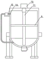
Fig. 1 is a schematic structural diagram of a mixing and stirring device for liquid disinfectant provided by the present invention.
Fig. 2 is a front view of the mixing and stirring device for liquid disinfectant provided by the present invention.
Fig. 3 is a cross-sectional view of the tank of the present invention.
Fig. 4 is a schematic connection diagram of the mounting ring, the connecting rod, the stirring ring and the filter screen according to the present invention.
In the figure: 1-tank body, 2-bracket, 3-feeding pipe, 4-discharging pipe, 5-electromagnetic valve, 6-stirring ring, 7-mounting ring, 8-connecting rod, 9-filter screen, 10-rotating motor, 11-screw rod, 12-mounting plate, 13-water pump, 14-water inlet pipe, 15-water outlet pipe and 16-nozzle.
Detailed Description
Reference will now be made in detail to embodiments of the present invention, examples of which are illustrated in the accompanying drawings, wherein like reference numerals refer to the same or similar elements or elements having the same or similar function throughout. The embodiments described below with reference to the drawings are exemplary and intended to be used for explaining the present invention, and should not be construed as limiting the present invention.
In the description of the present invention, it is to be understood that the terms "length", "width", "upper", "lower", "front", "rear", "left", "right", "vertical", "horizontal", "top", "bottom", "inner", "outer", and the like indicate orientations or positional relationships based on those shown in the drawings, and are merely for convenience of description and simplicity of description, and do not indicate or imply that the device or element being referred to must have a particular orientation, be constructed and operated in a particular orientation, and thus, should not be construed as limiting the present invention. In addition, in the description of the present invention, "a plurality" means two or more unless specifically limited otherwise.
Referring to fig. 1 to 4, the present invention provides a mixing and stirring device for liquid disinfectant, which comprises a tank body 1, a support 2, a feeding pipe 3, a discharging pipe 4, a stirring component and a circulating component;
the tank body 1 is fixedly connected with the support 2, the feeding pipe 3 is fixedly connected with the tank body 1 and is communicated with the interior of the tank body 1, the discharging pipe 4 is fixedly connected with the tank body 1 and is communicated with the interior of the tank body 1 and is positioned on one side of the tank body 1 far away from the feeding pipe 3, and the circulating component is arranged on the tank body 1;
stirring subassembly includes stirring ring 6, collar 7, connecting rod 8, filter screen 9 and drive component, drive component sets up jar body 1 is last, collar 7 passes through drive component is in rotate in jar body 1, connecting rod 8 with collar 7 fixed connection, and be located the outside of collar 7, stirring ring 6 with connecting rod 8 fixed connection, and be located connecting rod 8 is kept away from the one end of collar 7, filter screen 9 sets up collar 7 with between the stirring ring 6.
In this embodiment, the tank body 1 is installed on the ground through the support 2, there are two inlet pipes 3, which respectively extend into the tank body 1 from the upper surface of the tank body 1, the two inlet pipes 3 are used for adding disinfectant and water into the tank body 1, the outlet pipe 4 is arranged at the lower end of the tank body 1, the outlet pipe 4 is used for guiding the liquid disinfectant prepared by stirring out of the tank body 1, the annular surface circumference array of the installation ring 7 is provided with a plurality of connecting rods 8, one end of each connecting rod 8 far away from the installation ring 7 is fixed with the inner annular surface of the stirring ring 6, the outer diameter of the stirring ring 6 is the same as the inner diameter of the tank body 1, the filter screen 9 is installed in a blank area formed by connecting the installation ring 7, the connecting rods 8 and the stirring ring 6, so, through two inlet pipe 3 respectively to add disinfectant and water in the jar body 1, will after adding the opening closing cap of inlet pipe 3, through the drive component drive collar 7 removes, collar 7 drives filter screen 9 is in the inside of the jar body 1 reciprocates for disinfectant and water mix, through the stirring ring 6 with the inner wall contact of the jar body 1 to reciprocate and be in the adhesion disinfectant on the internal wall of the jar body 1 is scraped and is got, reduces being stained with of disinfectant on the internal wall of the jar body 1 attaches, makes to add the disinfectant of the internal portion of jar body 1 mixes with water more completely, thereby improves the utilization ratio of disinfectant raw materials.
Further, referring to fig. 1 to 3, the circulation assembly includes a mounting plate 12, a water pump 13, a water inlet pipe 14 and a water outlet pipe 15, the mounting plate 12 is fixedly connected to the tank 1 and is located outside the tank 1; the water pump 13 is arranged on the mounting plate 12; one end of the water inlet pipe 14 extends into the tank body 1, and the other end of the water inlet pipe is fixedly connected with the input end of the water pump 13; one end of the water outlet pipe 15 is fixedly connected with the output end of the water pump 13, and the other end of the water outlet pipe is communicated with the inside of the tank body 1.
Further, referring to fig. 3, the circulation assembly further includes a spray head 16, and the spray head 16 is fixedly connected to the water outlet pipe 15 and detachably connected to the tank 1.
In this embodiment, mounting panel 12 is installed the surface of the jar body 1, 13 bolt fastening of water pump is in on the mounting panel 12, the upper end of inlet tube 14 with the input fixed connection of water pump 13, the lower extreme of inlet tube 14 stretches into in the jar body 1, the left end of outlet pipe 15 with the output fixed connection of water pump 13, install the right-hand member of outlet pipe 15 shower nozzle 16, shower nozzle 16 with the mounting hole cooperation of the jar body 1, and with the inside intercommunication of the jar body 1, through water pump 13 is right the disinfectant of the inside below of the jar body 1 and the mixed liquid of water extract, and pass through shower nozzle 16 follows the spout of the inside upper end of the jar body 1, thereby it is right the mixed liquid of the jar body 1 inside circulates, and disinfectant and water mix with higher speed.
Further, referring to fig. 1 and fig. 3, the driving member includes a rotating motor 10 and a screw rod 11, the rotating motor 10 is fixedly connected to the tank 1 and is located on one side of the tank 1 close to the feeding pipe 3, and an output end of the rotating motor 10 extends into the tank 1; the screw rod 11 is fixedly connected with the output end of the rotating motor 10 and is rotatably connected with the mounting ring 7.
In this embodiment, the rotating motor 10 is installed on the upper surface of the tank body 1, the screw rod 11 is driven to rotate by the rotating motor 10, the screw rod 11 rotates to enable the installation ring 7 to perform up-and-down transmission on the screw rod 11, so that the filter screen 9 moves up and down in the tank body 1, the disinfectant and water are mixed, the installation ring 7 moves up and down on the screw rod 11 by controlling the forward and reverse rotation of the output end of the rotating motor 10, the moving distance of the installation ring 7 is limited by setting the rotating time of the output end of the rotating motor 10, and the installation ring 7 is prevented from moving away from the screw rod 11 or colliding with the tank body 1.
Further, referring to fig. 2, the mixing and stirring device for liquid disinfectant further includes an electromagnetic valve 5, and the electromagnetic valve 5 is disposed on the discharge pipe 4.
In this embodiment, the model of solenoid valve 5 is DN15, solenoid valve 5 sets up on discharging pipe 4, through solenoid valve 5 control opening or closing of discharging pipe 4 realizes that whether the autonomous control will prepare liquid disinfectant derives jar body 1.
The utility model discloses a liquid disinfectant's mixed agitating unit, through two inlet pipe 3 respectively to add disinfectant and water in the jar body 1, will after adding the opening closing cap of inlet pipe 3, through the drive component drive collar 7 removes, collar 7 drives filter screen 9 is in the inside of the jar body 1 reciprocates for disinfectant and water mix, through collar 6 with the inner wall contact of the jar body 1 to reciprocate and be in the adhesion disinfectant on the internal wall of the jar body 1 scrapes, reduces being stained with of disinfectant on the internal wall of the jar body 1 attaches, makes to add the disinfectant of the internal portion of jar body 1 mixes with water more completely to improve the utilization ratio of disinfectant raw materials.
While the invention has been described with reference to a preferred embodiment, it will be understood by those skilled in the art that various changes in form and details may be made therein without departing from the spirit and scope of the invention.
Claims (5)
1. A mixing and stirring device for a liquid disinfectant is characterized by comprising a tank body, a support, a feeding pipe, a discharging pipe, a stirring assembly and a circulating assembly;
the tank body is fixedly connected with the support, the feed pipe is fixedly connected with the tank body and is communicated with the interior of the tank body, the discharge pipe is fixedly connected with the tank body and is communicated with the interior of the tank body and is positioned on one side of the tank body, which is far away from the feed pipe, and the circulating assembly is arranged on the tank body;
the stirring assembly comprises a stirring ring, a mounting ring, a connecting rod, a filter screen and a driving member, wherein the driving member is arranged on the tank body, the mounting ring passes through the driving member to rotate in the tank body, the connecting rod is fixedly connected with the mounting ring and is positioned at the outer side of the mounting ring, the stirring ring is fixedly connected with the connecting rod and is positioned at one end of the mounting ring, and the filter screen is arranged between the mounting ring and the stirring ring.
2. Mixing and stirring device for liquid disinfectant according to claim 1,
the circulating assembly comprises a mounting plate, a water pump, a water inlet pipe and a water outlet pipe, and the mounting plate is fixedly connected with the tank body and is positioned on the outer side of the tank body; the water pump is arranged on the mounting plate; one end of the water inlet pipe extends into the tank body, and the other end of the water inlet pipe is fixedly connected with the input end of the water pump; one end of the water outlet pipe is fixedly connected with the output end of the water pump, and the other end of the water outlet pipe is communicated with the inside of the tank body.
3. Mixing and stirring device for liquid disinfectant according to claim 1,
the driving component comprises a rotating motor and a screw rod, the rotating motor is fixedly connected with the tank body and is positioned on one side of the tank body close to the feeding pipe, and the output end of the rotating motor extends into the tank body; the screw rod is fixedly connected with the output end of the rotating motor and is rotatably connected with the mounting ring.
4. Mixing device for liquid disinfectant according to claim 2,
the circulating component also comprises a spray head, and the spray head is fixedly connected with the water outlet pipe and is detachably connected with the tank body.
5. Mixing and stirring device for liquid disinfectant according to claim 1,
the mixing and stirring device for the liquid disinfectant further comprises an electromagnetic valve, and the electromagnetic valve is arranged on the discharge pipe.
Priority Applications (1)
| Application Number | Priority Date | Filing Date | Title |
|---|---|---|---|
| CN202123257932.9U CN217120118U (en) | 2021-12-21 | 2021-12-21 | Mixing and stirring device for liquid disinfectant |
Applications Claiming Priority (1)
| Application Number | Priority Date | Filing Date | Title |
|---|---|---|---|
| CN202123257932.9U CN217120118U (en) | 2021-12-21 | 2021-12-21 | Mixing and stirring device for liquid disinfectant |
Publications (1)
| Publication Number | Publication Date |
|---|---|
| CN217120118U true CN217120118U (en) | 2022-08-05 |
Family
ID=82618369
Family Applications (1)
| Application Number | Title | Priority Date | Filing Date |
|---|---|---|---|
| CN202123257932.9U Active CN217120118U (en) | 2021-12-21 | 2021-12-21 | Mixing and stirring device for liquid disinfectant |
Country Status (1)
| Country | Link |
|---|---|
| CN (1) | CN217120118U (en) |
Cited By (1)
| Publication number | Priority date | Publication date | Assignee | Title |
|---|---|---|---|---|
| CN116426333A (en) * | 2023-04-23 | 2023-07-14 | 舟山海珈生物工程有限公司 | Winterization treatment equipment and method for fish oil in fish oil extraction |
-
2021
- 2021-12-21 CN CN202123257932.9U patent/CN217120118U/en active Active
Cited By (2)
| Publication number | Priority date | Publication date | Assignee | Title |
|---|---|---|---|---|
| CN116426333A (en) * | 2023-04-23 | 2023-07-14 | 舟山海珈生物工程有限公司 | Winterization treatment equipment and method for fish oil in fish oil extraction |
| CN116426333B (en) * | 2023-04-23 | 2024-02-02 | 舟山海珈生物工程有限公司 | Winterization treatment equipment and method for fish oil in fish oil extraction |
Similar Documents
| Publication | Publication Date | Title |
|---|---|---|
| CN209934625U (en) | Agricultural fertilizer water preparation device | |
| CN217120118U (en) | Mixing and stirring device for liquid disinfectant | |
| CN110663513A (en) | Agricultural is with adding medicine and driping irrigation device | |
| CN108465438A (en) | One kind being convenient for clean wet granulator | |
| CN113617275B (en) | Mixing device and mixing method for quick-acting liquid topdressing | |
| CN108940077A (en) | Mixing device suitable for liquid bio-organic fertilizer | |
| CN210752385U (en) | Preparation device of drainage asphalt mixture | |
| CN211133943U (en) | Agitating unit is used in preparation of grignard formula alcohol | |
| CN213950705U (en) | Stirrer for flocculation reaction | |
| CN210683771U (en) | Mixing arrangement is used in sodium hyaluronate production | |
| CN212269680U (en) | Sewage treatment deposits device | |
| CN210419783U (en) | Preparation facilities for liquid manure | |
| CN107487752A (en) | A kind of disinfectant for animals dispensing apparatus | |
| CN210473705U (en) | Intelligent agricultural pesticide mixing equipment | |
| CN218358811U (en) | Agitating unit is used in water-soluble fertilizer production | |
| CN216022277U (en) | Atomizing and disinfecting device for cattle farm | |
| CN217756988U (en) | Sewage purification box with medicament feeding function | |
| CN215756910U (en) | Vertical multifunctional fermentation waste liquid sedimentation tank | |
| CN219879665U (en) | Automatic mixing device for farmland water and fertilizer irrigation liquid medicine | |
| CN219376844U (en) | Mixing device for emulsifier production | |
| CN210544460U (en) | A agitating unit for pesticide production | |
| CN213357085U (en) | Soak agitating unit that water transfer live bacteria was used | |
| CN214182755U (en) | Liquid manure agitating unit with prevent blockking up function | |
| CN218988777U (en) | Filling equipment is used in pesticide production that can stir misce bene | |
| CN214716602U (en) | Reaction kettle |
Legal Events
| Date | Code | Title | Description |
|---|---|---|---|
| GR01 | Patent grant | ||
| GR01 | Patent grant |