CN217108021U - Screw machine that shock attenuation performance is good - Google Patents
Screw machine that shock attenuation performance is good Download PDFInfo
- Publication number
- CN217108021U CN217108021U CN202220296555.5U CN202220296555U CN217108021U CN 217108021 U CN217108021 U CN 217108021U CN 202220296555 U CN202220296555 U CN 202220296555U CN 217108021 U CN217108021 U CN 217108021U
- Authority
- CN
- China
- Prior art keywords
- fixedly connected
- spring
- screw machine
- base
- sides
- Prior art date
- Legal status (The legal status is an assumption and is not a legal conclusion. Google has not performed a legal analysis and makes no representation as to the accuracy of the status listed.)
- Expired - Fee Related
Links
- 230000035939 shock Effects 0.000 title claims description 8
- 239000000872 buffer Substances 0.000 claims abstract description 24
- 238000010521 absorption reaction Methods 0.000 claims 5
- 238000013016 damping Methods 0.000 abstract description 11
- 230000003139 buffering effect Effects 0.000 description 3
- 239000000725 suspension Substances 0.000 description 3
- 230000001360 synchronised effect Effects 0.000 description 3
- 230000006835 compression Effects 0.000 description 2
- 238000007906 compression Methods 0.000 description 2
- 230000007774 longterm Effects 0.000 description 2
- 239000004568 cement Substances 0.000 description 1
- 238000004140 cleaning Methods 0.000 description 1
- 230000000694 effects Effects 0.000 description 1
- 238000009434 installation Methods 0.000 description 1
- 238000005461 lubrication Methods 0.000 description 1
- 238000012423 maintenance Methods 0.000 description 1
- 238000000034 method Methods 0.000 description 1
- 238000012986 modification Methods 0.000 description 1
- 230000004048 modification Effects 0.000 description 1
- 238000004663 powder metallurgy Methods 0.000 description 1
- 238000007789 sealing Methods 0.000 description 1
Images


Landscapes
- Vibration Prevention Devices (AREA)
Abstract
The utility model discloses a screw machine that damping performance is good relates to the screw machine field, the on-line screen storage device comprises a base, the top of base is seted up flutedly, the equal fixedly connected with guide arm in bottom of inner cavity of the base both sides, the inboard sliding connection on guide arm surface has the guide pin bushing, the outside cover on guide arm surface is equipped with first spring, the outside of first spring and inner cavity of the base's both sides fixed connection, the inboard of first spring and the outside fixed connection of guide pin bushing, the first fixed block of top fixedly connected with of guide pin bushing, the top of first fixed block has the ejector pin through round pin axle swing joint. The utility model provides a screw machine that damping performance is good, when the screw machine main part vibrations appear in the use, the screw machine main part carries out the buffer board on the fixed plate, and the fixed plate passes through rubber spring and cushions on the buffer beam, and the buffer beam cushions in the backup pad through the second spring, and the backup pad drives the slider and cushions in the spout.
Description
Technical Field
The utility model relates to a screw machine field, in particular to screw machine that shock attenuation performance is good.
Background
The screw machine is also called as a screw conveyor, the head and tail bearings move out of the shell, the suspension bearing adopts a sliding bearing and is provided with a dustproof sealing device, the discharge end is provided with a cleaning device, the positions of the feed and discharge ports are flexibly arranged, the bearing bush generally adopts powder metallurgy, the felt bearing bush is adopted for conveying cement, the suspension shaft and the screw shaft adopt a sliding block for connection, when the screw is disassembled, a driving device is not required to be moved, when the suspension bearing is disassembled, the screw is not required to be moved, the cover plate is not required to be disassembled for lubrication, the noise of the whole machine is low, the reliability is high, the service life is long, the adaptability is strong, and the installation and maintenance are convenient.
At present current screw machine, the damping performance is poor, and when people were using the screw machine, great vibrations appeared easily, in the long-term use, caused spare part easily to appear becoming flexible and drop, influenced its security, inconvenient people use.
Therefore, it is necessary to provide a screw machine with good damping performance to solve the above problems.
SUMMERY OF THE UTILITY MODEL
An object of the utility model is to provide a screw machine that damping performance is good to solve the current screw machine that proposes in the above-mentioned background art, damping performance is poor, when people are using the screw machine, great vibrations appear easily, in the long-term use, cause spare part to appear becoming flexible easily and drop, influence its security, the problem that inconvenient people used.
In order to achieve the above object, the utility model provides a following technical scheme: a screw machine with good damping performance comprises a base, wherein a groove is formed in the top of the base, guide rods are fixedly connected to the bottoms of two sides of an inner cavity of the base, a guide sleeve is slidably connected to the inner side of the surface of each guide rod, a first spring is sleeved on the outer side of the surface of each guide rod, the outer side of each first spring is fixedly connected with two sides of the inner cavity of the base, the inner side of each first spring is fixedly connected with the outer side of the guide sleeve, a first fixing block is fixedly connected to the top of each guide sleeve, the top of each first fixing block is movably connected with a push rod through a pin shaft, the top of each push rod is movably connected with a second fixing block through a pin shaft, a support plate is fixedly connected to the top of each second fixing block, spring pieces are fixedly connected to the front side and the rear side of the bottom of each support plate, the bottom of each spring piece is in contact with the bottom of the inner cavity of the base, and buffer rods are fixedly connected to the front side and the rear side of the top of each support plate, the top of buffer beam upwards runs through the base outside and fixedly connected with fixed plate, the top fixedly connected with screw machine main part of fixed plate.
Preferably, the surface cover of buffer lever is equipped with the second spring, the top of second spring and the bottom fixed connection of fixed plate, the bottom of second spring and the bottom fixed connection of recess inner chamber.
Preferably, both sides at the top of the base are fixedly connected with rubber springs, and the tops of the rubber springs are fixedly connected with the bottoms of the fixing plates.
Preferably, the bottom of the guide sleeve is fixedly connected with a pulley, and the bottom of the pulley is in contact with the bottom of the inner cavity of the base.
Preferably, the inner side of the guide rod is fixedly connected with a limiting block, and the outer side of the limiting block is in contact with the inner side of the guide sleeve.
Preferably, the top of base inner chamber both sides has all been seted up the spout, the inner chamber sliding connection of spout has the slider, the inboard both sides fixed connection with the backup pad of slider.
The utility model discloses a technological effect and advantage:
1. the utility model provides a screw machine with good damping performance, when the screw machine main body vibrates in the using process, the screw machine main body carries out a buffer plate on a fixed plate, the fixed plate buffers on a buffer rod through a rubber spring, the buffer rod buffers on a support plate through a second spring, and the support plate drives a slide block to buffer in a chute;
2. the utility model provides a screw machine that damping performance is good, the backup pad cushions on the spring plate simultaneously, increases the compressive property of backup pad, and synchronous backup pad cushions on the guide pin bushing through second fixed block, ejector pin and first fixed block, and the guide pin bushing outwards slides on the guide arm, and first spring this moment cushions the guide pin bushing, offsets the pressure of guide pin bushing, and then can guarantee the stability of fixed plate and screw machine main part.
Drawings
Fig. 1 is a schematic view of the overall structure of the present invention.
Fig. 2 is a sectional view of the base structure of the present invention.
Fig. 3 is a schematic perspective view of the structure of the support plate and the spring piece of the present invention.
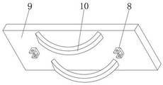
In the figure: 1. a base; 2. a groove; 3. a guide bar; 4. a guide sleeve; 5. a first spring; 6. a first fixed block; 7. a top rod; 8. a second fixed block; 9. a support plate; 10. a spring plate; 11. a buffer rod; 12. a fixing plate; 13. a screw machine main body; 14. a second spring; 15. a rubber spring; 16. a pulley; 17. a chute; 18. a slide block.
Detailed Description
The technical solutions in the embodiments of the present invention will be described clearly and completely with reference to the drawings in the embodiments of the present invention, and it is obvious that the described embodiments are only some embodiments of the present invention, not all embodiments. Based on the embodiments in the present invention, all other embodiments obtained by a person skilled in the art without creative work belong to the protection scope of the present invention.
The utility model provides a screw machine with good damping performance as shown in figures 1-3, which comprises a base 1, a groove 2 is arranged on the top of the base 1, guide rods 3 are fixedly connected with the bottoms of the two sides of the inner cavity of the base 1, guide sleeves 4 are slidably connected with the inner sides of the surfaces of the guide rods 3, first springs 5 are sleeved on the outer sides of the surfaces of the guide rods 3, the outer sides of the first springs 5 are fixedly connected with the two sides of the inner cavity of the base 1, the inner sides of the first springs 5 are fixedly connected with the outer sides of the guide sleeves 4, first fixing blocks 6 are fixedly connected with the tops of the guide sleeves 4, ejector rods 7 are movably connected with the tops of the first fixing blocks 6 through pin shafts, second fixing blocks 8 are movably connected with the tops of the ejector rods 7 through pin shafts, supporting plates 9 are fixedly connected with the tops of the second fixing blocks 8, spring pieces 10 are fixedly connected with the front sides and the rear sides of the bottoms of the supporting plates 9, the bottoms of the spring pieces 10 are contacted with the bottoms of the inner cavity of the base 1, the equal fixedly connected with buffer beam 11 in front side and the rear side at backup pad 9 top, the top of buffer beam 11 upwards runs through base 1 outside and fixedly connected with fixed plate 12, the top fixedly connected with screw machine main part 13 of fixed plate 12.
Further, the surface cover of buffer beam 11 is equipped with second spring 14, the top of second spring 14 and the bottom fixed connection of fixed plate 12, the bottom of second spring 14 and the bottom fixed connection of recess 2 inner chamber, when spiral shell body 13 vibrations appear in the use, spiral shell body 13 carries out the buffer board on fixed plate 12.
Further, the equal fixedly connected with rubber spring 15 in both sides at base 1 top, the top of rubber spring 15 and the bottom fixed connection of fixed plate 12, fixed plate 12 cushions on buffer beam 11 through rubber spring 15, and buffer beam 11 cushions in backup pad 9 through second spring 14, and backup pad 9 drives slider 18 and cushions in spout 17.
Furthermore, the bottom of the guide sleeve 4 is fixedly connected with a pulley 16, the bottom of the pulley 16 is in contact with the bottom of the inner cavity of the base 1, and meanwhile, the supporting plate 9 is buffered on the spring piece 10, so that the compression resistance of the supporting plate 9 is improved.
Furthermore, the inner side of the guide rod 3 is fixedly connected with a limiting block, the outer side of the limiting block is in contact with the inner side of the guide sleeve 4, the synchronous supporting plate 9 is buffered on the guide sleeve 4 through the second fixing block 8, the ejector rod 7 and the first fixing block 6, and the guide sleeve 4 slides outwards on the guide rod 3.
Further, the top of base 1 inner chamber both sides has all been seted up spout 17, and the inner chamber sliding connection of spout 17 has slider 18, and the inboard of slider 18 and the both sides fixed connection of backup pad 9, first spring 5 at this moment cushion guide pin bushing 4, offset the pressure of guide pin bushing 4, and then can guarantee the stability of fixed plate 12 and screw machine main part 13.
The utility model discloses the theory of operation: when the screw machine main body 13 shakes during use, the screw machine main body 13 is used for buffering on the fixing plate 12, the fixing plate 12 is buffered on the buffering rod 11 through the rubber spring 15, the buffering rod 11 is buffered on the supporting plate 9 through the second spring 14, the supporting plate 9 drives the sliding block 18 to buffer in the sliding groove 17, meanwhile, the supporting plate 9 is buffered on the spring piece 10, the compression resistance of the supporting plate 9 is improved, the synchronous supporting plate 9 is buffered on the guide sleeve 4 through the second fixing block 8, the ejector rod 7 and the first fixing block 6, the guide sleeve 4 slides outwards on the guide rod 3, the first spring 5 buffers the guide sleeve 4 at the moment, the pressure of the guide sleeve 4 is offset, and the stability of the fixing plate 12 and the screw machine main body 13 can be further guaranteed.
Finally, it should be noted that: although the present invention has been described in detail with reference to the foregoing embodiments, it will be apparent to those skilled in the art that modifications and variations can be made in the embodiments or in part of the technical features of the embodiments without departing from the spirit and the scope of the invention.
Claims (6)
1. The utility model provides a screw machine that shock attenuation performance is good, includes base (1), its characterized in that: the guide device is characterized in that a groove (2) is formed in the top of the base (1), guide rods (3) are fixedly connected to the bottoms of two sides of an inner cavity of the base (1), a guide sleeve (4) is connected to the inner side of the surface of the guide rod (3) in a sliding manner, a first spring (5) is sleeved on the outer side of the surface of the guide rod (3), the outer side of the first spring (5) is fixedly connected with two sides of the inner cavity of the base (1), the inner side of the first spring (5) is fixedly connected with the outer side of the guide sleeve (4), a first fixed block (6) is fixedly connected to the top of the guide sleeve (4), a push rod (7) is movably connected to the top of the first fixed block (6) through a pin shaft, a second fixed block (8) is movably connected to the top of the push rod (7) through a pin shaft, a support plate (9) is fixedly connected to the top of the second fixed block (8), spring pieces (10) are fixedly connected to the front side and the rear side of the bottom of the support plate (9), the bottom of spring leaf (10) and the bottom contact of base (1) inner chamber, the equal fixedly connected with buffer beam (11) of front side and the rear side at backup pad (9) top, the top of buffer beam (11) upwards runs through base (1) outside and fixedly connected with fixed plate (12), the top fixedly connected with screw machine main part (13) of fixed plate (12).
2. The screw machine with good shock absorption performance according to claim 1, wherein: the surface cover of buffer beam (11) is equipped with second spring (14), the top of second spring (14) and the bottom fixed connection of fixed plate (12), the bottom of second spring (14) and the bottom fixed connection of recess (2) inner chamber.
3. The screw machine with good shock absorption performance according to claim 1, wherein: the rubber spring fixing device is characterized in that rubber springs (15) are fixedly connected to the two sides of the top of the base (1), and the top of each rubber spring (15) is fixedly connected with the bottom of the fixing plate (12).
4. The screw machine with good shock absorption performance according to claim 1, wherein: the bottom of the guide sleeve (4) is fixedly connected with a pulley (16), and the bottom of the pulley (16) is in contact with the bottom of the inner cavity of the base (1).
5. The screw machine with good shock absorption performance according to claim 1, wherein: the inner side of the guide rod (3) is fixedly connected with a limiting block, and the outer side of the limiting block is in contact with the inner side of the guide sleeve (4).
6. The screw machine with good shock absorption performance according to claim 1, wherein: sliding grooves (17) are formed in the tops of two sides of an inner cavity of the base (1), sliding blocks (18) are connected to the inner cavity of the sliding grooves (17) in a sliding mode, and the inner sides of the sliding blocks (18) are fixedly connected with the two sides of the supporting plate (9).
Priority Applications (1)
| Application Number | Priority Date | Filing Date | Title |
|---|---|---|---|
| CN202220296555.5U CN217108021U (en) | 2022-02-15 | 2022-02-15 | Screw machine that shock attenuation performance is good |
Applications Claiming Priority (1)
| Application Number | Priority Date | Filing Date | Title |
|---|---|---|---|
| CN202220296555.5U CN217108021U (en) | 2022-02-15 | 2022-02-15 | Screw machine that shock attenuation performance is good |
Publications (1)
| Publication Number | Publication Date |
|---|---|
| CN217108021U true CN217108021U (en) | 2022-08-02 |
Family
ID=82598667
Family Applications (1)
| Application Number | Title | Priority Date | Filing Date |
|---|---|---|---|
| CN202220296555.5U Expired - Fee Related CN217108021U (en) | 2022-02-15 | 2022-02-15 | Screw machine that shock attenuation performance is good |
Country Status (1)
| Country | Link |
|---|---|
| CN (1) | CN217108021U (en) |
-
2022
- 2022-02-15 CN CN202220296555.5U patent/CN217108021U/en not_active Expired - Fee Related
Similar Documents
| Publication | Publication Date | Title |
|---|---|---|
| CN107720487B (en) | Shock attenuation noise control elevator | |
| CN208331571U (en) | Turntable foaming production line pedestal with shock-absorbing function | |
| CN217108021U (en) | Screw machine that shock attenuation performance is good | |
| CN213082925U (en) | Wear-resistant and low-friction pantograph of electric locomotive | |
| CN210259555U (en) | Automatic testing device for radio communication detection | |
| CN209787660U (en) | Circuit board with good pressure resistance | |
| CN111195849A (en) | Self-adaptive grinding mechanism | |
| CN214646936U (en) | Label printer with protection device | |
| CN210831040U (en) | Mechanical equipment vibration damping mount | |
| CN213795224U (en) | Closed hydrostatic guideway | |
| CN213271656U (en) | Computer vibration damping base | |
| CN214487801U (en) | Feeding mechanism of mining vibrating screen | |
| CN210851469U (en) | Hardware tool unloader with shock-absorbing function | |
| CN210376116U (en) | Coating analysis monitoring direct-reading spectrometer | |
| CN221084540U (en) | Shock-absorbing structure of running machine | |
| CN216382264U (en) | Amortization absorbing bearing frame | |
| CN217193866U (en) | Special guide rail for numerical control lathe for barrel machining | |
| CN218691017U (en) | Plunger type double-liquid glue valve with good wear resistance | |
| CN213982836U (en) | Buffering and damping device of movable computer | |
| CN212203086U (en) | Piston rod with hollow structure | |
| CN215788128U (en) | Guide rail for numerical control machine tool | |
| CN211440060U (en) | Mechanical arm joint structure | |
| CN216608224U (en) | A shock-absorbing structure for improving lathe stability | |
| CN214774032U (en) | 3D printing apparatus with good damping effect | |
| CN217583009U (en) | Shock absorption mechanism |
Legal Events
| Date | Code | Title | Description |
|---|---|---|---|
| GR01 | Patent grant | ||
| GR01 | Patent grant | ||
| CF01 | Termination of patent right due to non-payment of annual fee | ||
| CF01 | Termination of patent right due to non-payment of annual fee |
Granted publication date: 20220802 |