CN217080138U - Plastic-steel door and window frame section bar with multilayer ripple cavity - Google Patents
Plastic-steel door and window frame section bar with multilayer ripple cavity Download PDFInfo
- Publication number
- CN217080138U CN217080138U CN202220798012.3U CN202220798012U CN217080138U CN 217080138 U CN217080138 U CN 217080138U CN 202220798012 U CN202220798012 U CN 202220798012U CN 217080138 U CN217080138 U CN 217080138U
- Authority
- CN
- China
- Prior art keywords
- plastic
- steel door
- window frame
- section bar
- main body
- Prior art date
- Legal status (The legal status is an assumption and is not a legal conclusion. Google has not performed a legal analysis and makes no representation as to the accuracy of the status listed.)
- Active
Links
Images
Landscapes
- Securing Of Glass Panes Or The Like (AREA)
Abstract
A plastic-steel door and window frame section with a multilayer corrugated cavity relates to a plastic-steel door and window frame section. The utility model discloses a solve the cavity size in the current plastic-steel door and window section bar great, and the structure is the polygon, take place easily when receiving the transverse extrusion force and warp, and the relatively poor problem of heat preservation effect. The utility model comprises a section bar main body, at least three cavities with corrugated cross sections are sequentially arranged in the section bar main body from outside to inside; the maximum width of the corrugated cavity is 8-10 mm, and a glass clamping groove is formed in one side of the section main body. The utility model belongs to the architectural shape field.
Description
Technical Field
The utility model relates to a plastic-steel door and window frame section bar belongs to the architectural shape field.
Background
The frame of the window is made of polyvinyl chloride resin as a raw material, a certain proportion of a stabilizer, a coloring agent, a filler, an ultraviolet absorber and the like, and is extruded into a profile, so that the window is one of the most common window categories of modern buildings. The cavity size in the current plastic-steel door and window section bar is great, and the structure is the polygon, takes place to warp easily when receiving horizontal extrusion force, and keeps warm the effect relatively poor.
SUMMERY OF THE UTILITY MODEL
The utility model discloses a solve the cavity size in the current plastic-steel door and window section bar great, and the structure is the polygon, take place easily when receiving transverse extrusion force and warp, and the relatively poor problem of heat preservation effect, and then provide a plastic-steel door and window frame section bar with multilayer ripple cavity.
The utility model discloses a solve the technical scheme that above-mentioned problem was taken and be: the utility model comprises a section bar main body, wherein at least three cavities with corrugated cross sections are sequentially arranged in the section bar main body from outside to inside; the maximum width of the corrugated cavity is 8-10 mm, and a glass clamping groove is formed in one side of the section main body.
Furthermore, sealing strip clamping grooves are symmetrically arranged on the inner side wall of the glass clamping groove.
Furthermore, glass pressing plates are symmetrically arranged on the inner side walls of the glass clamping grooves and are located between the sealing strip clamping grooves and the section bar main body.
Furthermore, a positioning groove is formed in the inner bottom surface of the glass clamping groove.
Furthermore, the length of the corrugated cavity is 50 mm-100 mm.
Further, the sealing strip clamping groove is provided with an outer edge which is inclined inwards, and the inclination angle of the outer edge is 45 degrees.
The utility model has the advantages that: the utility model divides the main body of the section into a plurality of narrow cavities, and the narrow cavities are filled with air, so that the heat insulation effect of the whole section is improved because the air heat conductivity coefficient is lower; the utility model adopts the corrugated cavity which can greatly improve the capability of resisting the transverse extrusion force of the section bar and avoid the section bar deformation caused by the expansion with heat and contraction with cold of the glass or other accessories after the section bar is suitable for a short time; the utility model discloses simple structure, low in manufacturing cost, simple to operate is swift.
Drawings
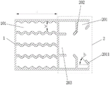
Fig. 1 is a schematic cross-sectional structure of the present invention.
Detailed Description
The first embodiment is as follows: the present embodiment is described with reference to fig. 1, and the plastic-steel door/window frame profile with a multilayer corrugated cavity according to the present embodiment includes a profile main body 1, wherein at least three cavities 101 with corrugated cross sections are sequentially arranged in the profile main body 1 from outside to inside; the maximum width W of the corrugated cavity 101 is 8-10 mm, and one side of the section bar main body 1 is provided with a glass clamping groove 2.
The second embodiment is as follows: the present embodiment is described with reference to fig. 1, and the inner side wall of the glass clamping groove 2 of the plastic-steel door/window frame profile with the multi-layer corrugated cavity is symmetrically provided with sealing strip clamping grooves 201. Other components and connections are the same as those in the first embodiment.
The third concrete implementation mode: the present embodiment is described with reference to fig. 1, in which glass pressing plates 202 are symmetrically disposed on the inner side walls of glass clamping grooves 2 of a plastic-steel door/window frame profile with a multi-layer corrugated cavity, and the glass pressing plates 202 are located between a sealing strip clamping groove 201 and a profile body 1.
So set up, can be pressed tightly by the compaction after the glass installation, avoid it to rock. Other components and connection relationships are the same as those in the first or second embodiment.
The fourth concrete implementation mode: referring to fig. 1, the present embodiment is described, and a positioning groove 203 is formed on the inner bottom surface of a glass clamping groove 2 of a plastic-steel door/window frame profile with a multi-layer corrugated cavity according to the present embodiment.
So set up, make things convenient for glass installation and location, improve the installation effectiveness.
Other components and connections are the same as those in the first embodiment.
The fifth concrete implementation mode: the present embodiment is described with reference to fig. 1, and the length H of the corrugated cavity 101 of the plastic-steel sash profile with a multi-layer corrugated cavity according to the present embodiment is 50mm to 100 mm. Other components and connections are the same as those in the first embodiment.
The sixth specific implementation mode: the present embodiment is described with reference to fig. 1, in which the sealing strip slot 201 of the plastic-steel door/window frame profile with the multi-layer corrugated cavity is provided with an outer edge 2011 that is inclined inward, and an inclination angle a of the outer edge 2011 is 45 °. Other components and connection relationships are the same as those in the second embodiment.
The above description is only a preferred embodiment of the present invention, and is not intended to limit the present invention in any way, and although the present invention has been disclosed with reference to the preferred embodiment, it is not intended to limit the present invention, and any person skilled in the art can make some changes or modifications to equivalent embodiments without departing from the scope of the present invention, and all those skilled in the art can make modifications or modifications equivalent embodiments without departing from the technical spirit of the present invention.
Claims (6)
1. The utility model provides a mould steel door and window frame section bar with multilayer ripple cavity, its characterized in that: the plastic-steel door and window frame profile with the multilayer corrugated cavities comprises a profile main body (1), wherein at least three cavities (101) with corrugated cross sections are sequentially arranged in the profile main body (1) from outside to inside; the maximum width (W) of the corrugated cavity (101) is 8-10 mm, and a glass clamping groove (2) is arranged on one side of the section main body (1).
2. The plastic-steel door and window frame profile with the multilayer corrugated cavities as claimed in claim 1, wherein: the inner side wall of the glass clamping groove (2) is symmetrically provided with sealing strip clamping grooves (201).
3. The plastic-steel door and window frame profile with the multilayer corrugated cavities as claimed in claim 1 or 2, wherein: the glass pressing plates (202) are symmetrically arranged on the inner side wall of the glass clamping groove (2), and the glass pressing plates (202) are located between the sealing strip clamping groove (201) and the section bar main body (1).
4. The plastic-steel door and window frame profile with the multilayer corrugated cavities as claimed in claim 1, wherein: the inner bottom surface of the glass clamping groove (2) is provided with a positioning groove (203).
5. The plastic-steel door and window frame profile with the multilayer corrugated cavities as claimed in claim 1, wherein: the length (H) of the corrugated cavity (101) is 50mm to 100 mm.
6. The plastic-steel door and window frame profile with the multilayer corrugated cavities as claimed in claim 2, wherein: the sealing strip clamping groove (201) is provided with an outer edge (2011) which is inclined inwards, and the inclination angle (A) of the outer edge (2011) is 45 degrees.
Priority Applications (1)
| Application Number | Priority Date | Filing Date | Title |
|---|---|---|---|
| CN202220798012.3U CN217080138U (en) | 2022-04-07 | 2022-04-07 | Plastic-steel door and window frame section bar with multilayer ripple cavity |
Applications Claiming Priority (1)
| Application Number | Priority Date | Filing Date | Title |
|---|---|---|---|
| CN202220798012.3U CN217080138U (en) | 2022-04-07 | 2022-04-07 | Plastic-steel door and window frame section bar with multilayer ripple cavity |
Publications (1)
| Publication Number | Publication Date |
|---|---|
| CN217080138U true CN217080138U (en) | 2022-07-29 |
Family
ID=82554609
Family Applications (1)
| Application Number | Title | Priority Date | Filing Date |
|---|---|---|---|
| CN202220798012.3U Active CN217080138U (en) | 2022-04-07 | 2022-04-07 | Plastic-steel door and window frame section bar with multilayer ripple cavity |
Country Status (1)
| Country | Link |
|---|---|
| CN (1) | CN217080138U (en) |
-
2022
- 2022-04-07 CN CN202220798012.3U patent/CN217080138U/en active Active
Similar Documents
| Publication | Publication Date | Title |
|---|---|---|
| CN203050365U (en) | Novel double bridge cutoff aluminum plastic coextrusion filling composite section bars | |
| CN104612538B (en) | Composite door and window profile combined by inner and outer metal profiles and middle integral heat insulation profile | |
| CN102628333A (en) | Heat insulating bridge-cut-off aluminum-plastic co-extrusion profile | |
| CN217080138U (en) | Plastic-steel door and window frame section bar with multilayer ripple cavity | |
| CN204552477U (en) | The composite door and window frame section bar of filling with insulation material in the middle aluminium chamber of a kind of thermal insulation | |
| US20060000163A1 (en) | Insulation cage | |
| CN215054208U (en) | Green energy-saving assembly type building wall with sealing assembly | |
| CN214365654U (en) | Aluminum alloy section with heat insulation function | |
| CN206583064U (en) | Assembled frame of air conditioner and its column | |
| CN202227543U (en) | Energy-saving glass curtain wall structure | |
| CN201502862U (en) | Elastic expandable metal and nonmetal combined sectional material | |
| CN203822090U (en) | Thermal insulation bridge-cutoff aluminum alloy section door and window | |
| CN202970365U (en) | High-tensile, energy-saving and environmentally-friendly window with three sealed cavities | |
| CN208294337U (en) | A kind of window pair frame installed for plastics or aluminium plastic co-extruding door and window dry method | |
| CN217354165U (en) | Energy-saving fireproof bridge-cut-off aluminum door and window profile and energy-saving fireproof bridge-cut-off aluminum door and window | |
| CN216446757U (en) | Lattice sandwich structure's antidetonation type plastic steel window frame section bar | |
| CN216974646U (en) | Aluminum-plastic co-extrusion profile structure | |
| CN214424315U (en) | Aluminum-plastic composite energy-saving door and window curtain wall section bar capable of being assembled | |
| CN217354120U (en) | Aluminum-plastic composite insertion structure and aluminum-plastic composite profile | |
| CN201412025Y (en) | Window frame section bar of single-sashed two-casement four-glass window | |
| CN220868540U (en) | Flexible sealed unitized curtain wall system | |
| CN216841184U (en) | Sectional material structure for doors and windows | |
| CN215166985U (en) | Mounting structure capable of realizing rear mounting of unit curtain wall | |
| CN215978995U (en) | Heat-preservation and heat-insulation aluminum alloy door and window | |
| CN216894029U (en) | Low-cost high-strength heat-insulation aluminum alloy frame for casement window |
Legal Events
| Date | Code | Title | Description |
|---|---|---|---|
| GR01 | Patent grant | ||
| GR01 | Patent grant |