CN217049934U - Coal mine solid filling material feeding equipment - Google Patents
Coal mine solid filling material feeding equipment Download PDFInfo
- Publication number
- CN217049934U CN217049934U CN202220633990.2U CN202220633990U CN217049934U CN 217049934 U CN217049934 U CN 217049934U CN 202220633990 U CN202220633990 U CN 202220633990U CN 217049934 U CN217049934 U CN 217049934U
- Authority
- CN
- China
- Prior art keywords
- chamber
- cavity
- buffer
- filling material
- blanking
- Prior art date
- Legal status (The legal status is an assumption and is not a legal conclusion. Google has not performed a legal analysis and makes no representation as to the accuracy of the status listed.)
- Active
Links
Images


Landscapes
- Jigging Conveyors (AREA)
Abstract
The utility model discloses a coal mine solid filling material feeding device, which relates to the technical field of coal mining, and is inconvenient for vibrating and blanking a blanking pipe, so that the blanking pipe is easy to block during blanking, a feed inlet is arranged at the top end of a feed cavity, a blanking plate is arranged inside the feed cavity, a buffer cavity is arranged at the bottom end of the feed cavity, a buffer mechanism is arranged inside the buffer cavity, a vibrating mechanism is arranged inside the mounting cavity, the buffer mechanism and the blanking plate are mutually matched to buffer the feeding of filling materials, the vibrating mechanism can drive a discharge port to vibrate and prevent blocking, the utility model discloses a vibrating mechanism is arranged inside the mounting cavity, and the discharge port can vibrate during blanking by utilizing the mutual matching of the vibrating mechanism, so that the discharge port is not easy to block during blanking, the working efficiency of the equipment is improved when the equipment is used, and therefore the practicability of the equipment is greatly improved when the equipment is used.
Description
Technical Field
The utility model relates to a coal mining technology field specifically is a colliery solid filling material throws material equipment.
Background
Along with the development background of economy, the living standard of people is continuously improved, the development of the mining industry of China is very rapid, a mine goaf is an underground goaf left after mining, and if the mine goaf is not filled, the ground is collapsed, so that danger is brought, solid filling materials are required to be used for carrying out the coal mine goaf, the main materials filled in the current coal mine goaf are gangue, and in addition, coal dust, steel slag and the like, so that feeding equipment is required to be used for feeding treatment;
the existing feeding equipment has the following problems in use:
1. when the existing feeding equipment is used, the blanking pipe is not convenient to shake and blank, so that the blanking pipe is easy to block during blanking, the working efficiency of the equipment is reduced during use, and the practicability of the equipment is reduced;
2. when the existing feeding equipment is used, the solid material is buffered and descended inconveniently, so that the solid material is influenced by gravity and is fed at a high speed when being fed, the equipment is easily damaged, and the service life of the equipment is shortened.
Therefore, a coal mine solid filling material feeding device is provided for solving the problems.
SUMMERY OF THE UTILITY MODEL
The utility model aims at providing a colliery solid filling material throws material equipment to solve the problem that proposes in the above-mentioned background art.
In order to achieve the above object, the utility model provides a following technical scheme: the utility model provides a colliery solid filling material throws material equipment, includes the feeding chamber, the feed inlet is installed on the top in feeding chamber, the internally mounted in feeding chamber has the blanking board, the cushion chamber is installed to the bottom in feeding chamber, the inside of cushion chamber is provided with buffer gear, the buffer board is installed on buffer gear's top, the discharge gate is installed to the both sides of cushion chamber bottom, the installation cavity is installed to the bottom of cushion chamber, the inside of installation cavity is provided with vibrations mechanism, mutually supporting of buffer gear and blanking board cushions the processing when can be to filling material's feeding, vibrations mechanism can drive the discharge gate and shake and prevent to block up.
As a preferred technical scheme of the utility model, vibrations mechanism includes spacing subassembly and power component, spacing subassembly includes telescopic link and expanding spring, the telescopic link is installed in the both sides of cushion chamber bottom and the both sides of installation cavity, the lateral wall of telescopic link is provided with expanding spring, the one end of telescopic link is connected with the one end of discharge gate.
As a preferred technical scheme of the utility model, power component includes fixed plate, servo motor, carousel, driven runner, movable frame, transfer line and spacing wheel, the fixed plate is installed in the inside of installation cavity, servo motor is installed to the one end of fixed plate, the internally mounted of fixed plate has the carousel, servo motor's output is connected with the one end of carousel, the other end of carousel is connected with driven runner, driven runner's lateral wall is provided with the movable frame, the transfer line is installed to the both sides of movable frame, the one end of transfer line extends to the outside of installation cavity, spacing wheel is installed to the both sides of fixed plate one end.
As a preferred technical scheme of the utility model, spacing round is provided with two sets ofly, and every group is two, two spacing round carries out spacing processing to the transfer line.
As a preferred technical scheme of the utility model, the blanking plate is provided with four, the blanking plate is the slope design, four in the inside in feeding chamber be symmetric distribution about the axis in feeding chamber between the blanking plate.
As a preferred technical scheme of the utility model, buffer gear includes fixed chamber, reset spring, fly leaf, movable rod and guide structure, fixed chamber is installed in the inside bottom of buffer chamber, reset spring is installed to the inside bottom in fixed chamber, the fly leaf is installed on reset spring's top, the movable rod is installed on the top of fly leaf, the top of movable rod extends to the outside in fixed chamber, the top of movable rod is connected with the bottom of buffer board.
As a preferred technical scheme of the utility model, guide structure includes spacing groove and stopper, the spacing groove sets up in the both sides of fixed intracavity portion, the inside of spacing groove is provided with the stopper, the one end of stopper is connected with the one end of fly leaf.
Compared with the prior art, the beneficial effects of the utility model reside in that:
1. the utility model discloses a be provided with the vibrations mechanism in the inside of installation cavity, utilize the telescopic link of vibrations mechanism, expanding spring, fixed plate, servo motor, carousel, driven runner, movable frame, transfer line and spacing round mutually support, can act on vibrations to the discharge gate when unloading, make this discharge gate difficult for blockking up when unloading, improved the work efficiency of this equipment when using to the practicality of this equipment when using has been greatly improved;
2. the utility model discloses a be provided with buffer gear in the inside of cushion chamber, utilize mutually supporting of buffer gear's fixed chamber, reset spring, fly leaf, movable rod, spacing groove, stopper and blanking board, can cushion the processing to solid filler material when the unloading for solid material's speed when the unloading becomes slow, and the impact force that causes is less, is difficult for causing the damage to this equipment, thereby prolongs the life of this equipment greatly.
Drawings
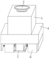
FIG. 1 is a schematic view of the overall structure of the present invention,
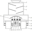
FIG. 2 is a schematic front sectional view of the buffering mechanism of the present invention,
FIG. 3 is a schematic side view of the vibration mechanism of the present invention,
fig. 4 is a schematic view of a partially enlarged structure at a position in fig. 2 according to the present invention.
In the figure: 1. a feed cavity; 2. a feed inlet; 3. a blanking plate; 4. a buffer chamber; 5. a buffer plate; 6. a discharge port; 7. a mounting cavity; 8. a telescopic rod; 9. a tension spring; 10. a fixing plate; 11. a servo motor; 12. a turntable; 13. a driven runner; 14. a movable frame; 15. a transmission rod; 16. a limiting wheel; 17. a fixed cavity; 18. a return spring; 19. a movable plate; 20. a movable rod; 21. a limiting groove; 22. and a limiting block.
Detailed Description
The technical solutions in the embodiments of the present invention will be described clearly and completely with reference to the drawings in the embodiments of the present invention, and it is obvious that the described embodiments are only some embodiments of the present invention, not all embodiments. Based on the embodiments in the present invention, all other embodiments obtained by a person skilled in the art without creative efforts all belong to the protection scope of the present invention.
Example (b): as shown in figures 1-4, the utility model provides a coal mine solid filling material feeding device, which comprises a feeding cavity 1, a feeding inlet 2 is arranged at the top end of the feeding cavity 1, blanking plates 3 are arranged inside the feeding cavity 1, four blanking plates 3 are arranged inside the feeding cavity 1, the four blanking plates 3 are in an inclined design, the four blanking plates 3 are symmetrically distributed around the central axis of the feeding cavity 1, a buffer cavity 4 is arranged at the bottom end of the feeding cavity 1, a buffer mechanism is arranged inside the buffer cavity 4, a buffer plate 5 is arranged at the top end of the buffer mechanism, discharge ports 6 are arranged at two sides of the bottom end of the buffer cavity 4, an installation cavity 7 is arranged at the bottom end of the buffer cavity 4, a vibration mechanism is arranged inside the installation cavity 7, and the buffer mechanism is matched with the blanking plates 3, buffering treatment can be carried out during the feeding of filling materials, and the vibration mechanism can drive the discharge hole 6 to vibrate so as to prevent blockage.
Further, the vibration mechanism comprises a limiting component and a power component, the limiting component comprises a telescopic rod 8 and a telescopic spring 9, the telescopic rod 8 is installed on two sides of the bottom end of the buffer cavity 4 and two sides of the installation cavity 7, the telescopic spring 9 is arranged on the outer side wall of the telescopic rod 8, one end of the telescopic rod 8 is connected with one end of the discharge hole 6, the power component comprises a fixed plate 10, a servo motor 11, a rotary plate 12, a driven rotary wheel 13, a movable frame 14, a transmission rod 15 and a limiting wheel 16, the fixed plate 10 is installed inside the installation cavity 7, the servo motor 11 is installed at one end of the fixed plate 10, the rotary plate 12 is installed inside the fixed plate 10, the output end of the servo motor 11 is connected with one end of the rotary plate 12, the other end of the rotary plate 12 is connected with the driven rotary wheel 13, the movable frame 14 is arranged on the outer side wall of the driven rotary wheel 13, the transmission rods 15 are installed on two sides of the movable frame 14, one end of the transmission rod 15 extends to the outside the installation cavity 7, spacing wheel 16 is installed to the both sides of fixed plate 10 one end, spacing wheel 16 is provided with two sets ofly, every group is two, two spacing wheels 16 carry out spacing processing to transfer line 15, in using, solid filling material carries out the ejection of compact through discharge gate 6, it rotates to start servo motor 11 and drive carousel 12 this moment, the event drives movable frame 14 through driven runner 13 and rotates, and then under spacing of spacing wheel 16, it removes reciprocating motion to move about moving transfer line 15 through movable frame 14 drive, and then under telescopic link 8 and expanding spring 9's spacing, it controls about moving discharge gate 6 to drive through transfer line 15, it shakes to drive discharge gate 6, make this discharge gate 6 be difficult for blockking up when the unloading, the work efficiency of this equipment when using has been improved, thereby the practicality of this equipment when using has been improved greatly.
Further, the buffer mechanism comprises a fixed cavity 17, a reset spring 18, a movable plate 19, a movable rod 20 and a guide structure, the fixed cavity 17 is installed at the bottom end inside the buffer cavity 4, the reset spring 18 is installed at the bottom end inside the fixed cavity 17, the movable plate 19 is installed at the top end of the reset spring 18, the movable rod 20 is installed at the top end of the movable plate 19, the top end of the movable rod 20 extends to the outside of the fixed cavity 17, the top end of the movable rod 20 is connected with the bottom end of the buffer plate 5, the guide structure comprises a limiting groove 21 and limiting blocks 22, the limiting groove 21 is arranged at two sides inside the fixed cavity 17, the limiting blocks 22 are arranged inside the limiting groove 21, one end of each limiting block 22 is connected with one end of the movable plate 19, during use, the filling material can be conveyed to the inside of the buffer cavity 4 by the transmission of the blanking plate 3, the solid filling material impacts on the buffer plate 5, at the moment, the reset spring 18 is acted by elasticity, under spacing of spacing groove 21 and stopper 22, drive fly leaf 19 and movable rod 20 and move about telescopically, and then drive buffer board 5 through multiunit movable rod 20 and stretch out and draw back for the impact force that this equipment received is less, can cushion solid filler material when the unloading, makes the speed of solid material when the unloading slow down, and the impact force that causes is less, is difficult for causing the damage to this equipment, thereby prolongs the life of this equipment greatly.
The working principle is as follows: the solid filling material is firstly placed into the feeding cavity 1 from the feeding hole 2 by a worker, the solid filling material falls onto the blanking plate 3, due to the inclined design of the blanking plate 3, the filling material can be conveyed into the buffer cavity 4 by the transmission of the blanking plate 3, the solid filling material impacts on the buffer plate 5, at the moment, the reset spring 18 is under the action of elastic force, under the limit of the limit groove 21 and the limit block 22, the movable plate 19 and the movable rods 20 are driven to move in a telescopic manner, and then the buffer plate 5 is driven to extend and retract through the plurality of groups of movable rods 20, so that the impact force on the equipment is small, the solid filling material can be buffered during blanking, the speed of the solid material during blanking is reduced, the impact force is small, the equipment is not easy to be damaged, the service life of the equipment is greatly prolonged, and then the solid filling material is discharged through the discharge hole 6, starting servo motor 11 at this moment and driving carousel 12 and rotate, so drive movable frame 14 through driven runner 13 and rotate, and then under spacing round 16, it removes reciprocating motion about moving transfer line 15 is to drive through movable frame 14, and then under telescopic link 8 and expanding spring 9 are spacing, it removes about driving discharge gate 6 through transfer line 15 drive, it shakes to drive discharge gate 6, make this discharge gate 6 difficult jam when the unloading, the work efficiency of this equipment when using has been improved, thereby the practicality of this equipment when using has been improved greatly, accomplish throwing of fixed filling material, then solid filling material carries appropriate position through transmission device.
Although embodiments of the present invention have been shown and described, it will be appreciated by those skilled in the art that various changes, modifications, substitutions and alterations can be made in these embodiments without departing from the principles and spirit of the invention, the scope of which is defined in the appended claims and their equivalents.
Claims (7)
1. The utility model provides a colliery solid filling material throws material equipment, includes feeding chamber (1), its characterized in that: feed inlet (2) are installed on the top of feeding chamber (1), the internally mounted of feeding chamber (1) has blanking plate (3), cushion chamber (4) are installed to the bottom of feeding chamber (1), the inside of cushion chamber (4) is provided with buffer gear, buffer plate (5) are installed on buffer gear's top, discharge gate (6) are installed to the both sides of cushion chamber (4) bottom, installation cavity (7) are installed to the bottom of cushion chamber (4), the inside of installation cavity (7) is provided with vibrations mechanism, buffer gear and blanking plate (3) mutually support, cushion the processing when can be to the feeding of filling material, vibrations mechanism can drive discharge gate (6) and shake and prevent to block up.
2. The coal mine solid filling material feeding device according to claim 1, characterized in that: vibrations mechanism includes spacing subassembly and power component, spacing subassembly includes telescopic link (8) and expanding spring (9), the both sides in buffer chamber (4) bottom and the both sides of installation cavity (7) are installed in telescopic link (8), the lateral wall of telescopic link (8) is provided with expanding spring (9), the one end of telescopic link (8) is connected with the one end of discharge gate (6).
3. The coal mine solid packing material feeding device according to claim 2, wherein: the power component comprises a fixed plate (10), a servo motor (11), a rotary disc (12), a driven rotary wheel (13), a movable frame (14), a transmission rod (15) and a limiting wheel (16), the fixing plate (10) is arranged in the mounting cavity (7), one end of the fixing plate (10) is provided with a servo motor (11), a rotary table (12) is arranged in the fixed plate (10), the output end of the servo motor (11) is connected with one end of the rotary table (12), the other end of the turntable (12) is connected with a driven rotating wheel (13), the outer side wall of the driven rotating wheel (13) is provided with a movable frame (14), transfer line (15) are installed to the both sides of activity frame (14), the one end of transfer line (15) extends to the outside of installation cavity (7), spacing round (16) are installed to the both sides of fixed plate (10) one end.
4. The coal mine solid filling material feeding device according to claim 3, characterized in that: the limiting wheels (16) are arranged in two groups, each group comprises two limiting wheels, and the limiting wheels (16) limit the transmission rod (15).
5. The coal mine solid filling material feeding device according to claim 1, characterized in that: the feeding device is characterized in that the number of the blanking plates (3) is four, the blanking plates (3) are designed to be inclined in the feeding cavity (1), and the four blanking plates (3) are symmetrically distributed relative to the central axis of the feeding cavity (1).
6. The coal mine solid filling material feeding device according to claim 1, characterized in that: buffer gear is including fixed chamber (17), reset spring (18), fly leaf (19), movable rod (20) and guide structure, install in buffer chamber (4) inside bottom in fixed chamber (17), reset spring (18) are installed to the inside bottom in fixed chamber (17), fly leaf (19) are installed on the top of reset spring (18), movable rod (20) are installed on the top of fly leaf (19), the top of movable rod (20) extends to the outside in fixed chamber (17), the top of movable rod (20) is connected with the bottom of buffer board (5).
7. The coal mine solid filling material feeding device according to claim 6, characterized in that: the guide structure comprises a limiting groove (21) and a limiting block (22), the limiting groove (21) is arranged on two sides of the inside of the fixed cavity (17), the limiting block (22) is arranged inside the limiting groove (21), and one end of the limiting block (22) is connected with one end of the movable plate (19).
Priority Applications (1)
| Application Number | Priority Date | Filing Date | Title |
|---|---|---|---|
| CN202220633990.2U CN217049934U (en) | 2022-03-23 | 2022-03-23 | Coal mine solid filling material feeding equipment |
Applications Claiming Priority (1)
| Application Number | Priority Date | Filing Date | Title |
|---|---|---|---|
| CN202220633990.2U CN217049934U (en) | 2022-03-23 | 2022-03-23 | Coal mine solid filling material feeding equipment |
Publications (1)
| Publication Number | Publication Date |
|---|---|
| CN217049934U true CN217049934U (en) | 2022-07-26 |
Family
ID=82490238
Family Applications (1)
| Application Number | Title | Priority Date | Filing Date |
|---|---|---|---|
| CN202220633990.2U Active CN217049934U (en) | 2022-03-23 | 2022-03-23 | Coal mine solid filling material feeding equipment |
Country Status (1)
| Country | Link |
|---|---|
| CN (1) | CN217049934U (en) |
-
2022
- 2022-03-23 CN CN202220633990.2U patent/CN217049934U/en active Active
Similar Documents
| Publication | Publication Date | Title |
|---|---|---|
| CN204485984U (en) | A kind of mine rock material disintegrating machine with dustproof effect | |
| CN217049934U (en) | Coal mine solid filling material feeding equipment | |
| CN215235690U (en) | Big, medium and small splitter of navel orange | |
| CN113387113B (en) | Many materials band conveyer with shock-absorbing function | |
| CN213474423U (en) | Buffer mechanism for reducing chain plate impact of plate type feeding machine | |
| CN213325405U (en) | Scraper conveyer in mine | |
| CN110975972B (en) | Coal material crushing device for coal mine | |
| CN213863928U (en) | Belt conveyor for mine exploitation | |
| CN219362298U (en) | Electromechanical transmission conveyer for coal mine | |
| CN220664258U (en) | Belt feeder coal drop point buffering dust collector | |
| CN220563641U (en) | Discharge hopper of impact type polycrystalline silicon sand making machine | |
| CN212821155U (en) | Product and abrasive material sorting unit | |
| CN214691703U (en) | Automatic feeding device of coal vibrations | |
| CN215927384U (en) | Coal mining machine safety protection device for coal mining | |
| CN210854019U (en) | Concrete production raw material conveyor | |
| CN109397582A (en) | A kind of plastic crushing equipment convenient for feeding | |
| CN212355371U (en) | Simple belt conveyor for underground coal mine electromechanical transportation | |
| CN219362423U (en) | Cable protection pipe even unloading structure | |
| CN209834813U (en) | Novel double-helix feeding machine | |
| CN214868086U (en) | Laser cutting device of automobile starter isolator | |
| CN220949867U (en) | Adhesive tape cleaning and conveying limiting device | |
| CN217512019U (en) | Damping and noise-reducing structure of crushing sand making machine | |
| CN219905909U (en) | Conveyor for mining system | |
| CN216037211U (en) | Novel three-dimensional package carousel stock stop | |
| CN214731999U (en) | High-efficient heavy plate-type feeding machine of bi-motor drive |
Legal Events
| Date | Code | Title | Description |
|---|---|---|---|
| GR01 | Patent grant | ||
| GR01 | Patent grant |