CN217044871U - Forklift truck wheel carrier reaming machine - Google Patents
Forklift truck wheel carrier reaming machine Download PDFInfo
- Publication number
- CN217044871U CN217044871U CN202220279036.8U CN202220279036U CN217044871U CN 217044871 U CN217044871 U CN 217044871U CN 202220279036 U CN202220279036 U CN 202220279036U CN 217044871 U CN217044871 U CN 217044871U
- Authority
- CN
- China
- Prior art keywords
- reaming
- wheel carrier
- forklift
- processing platform
- forklift truck
- Prior art date
- Legal status (The legal status is an assumption and is not a legal conclusion. Google has not performed a legal analysis and makes no representation as to the accuracy of the status listed.)
- Active
Links
Images


Abstract
The utility model provides a fork truck wheel carrier reaming machine belongs to processing equipment technical field, include: the device comprises a rack, wherein a support bracket is arranged on the rack, a processing platform for placing a forklift wheel carrier is arranged on the support bracket, and a limiting component for preventing the forklift wheel carrier from moving or rotating in the processing process is arranged at a position corresponding to the processing platform; and the reaming assembly is movably arranged on the rack and comprises a plurality of reaming tools, and the position of each reaming tool corresponds to the position of the shaft hole on the forklift wheel carrier one by one. The utility model discloses a reaming subassembly accomplishes the reaming processing in each shaft hole on the fork truck wheel carrier, has guaranteed the uniformity of shaft hole processing on the one hand, and on the other hand has improved work efficiency, has reduced corresponding working strength.
Description
Technical Field
The utility model belongs to the technical field of the processing equipment, a fork truck wheel carrier fraising machine is related to.
Background
The forklift plays a very important role in a logistics system of an enterprise, is a masterforce army in material handling equipment, is widely applied to various departments of national economy such as stations, ports, airports, factories, warehouses and the like, and is efficient equipment for mechanical loading, unloading, stacking and short-distance transportation.
At present, the fork truck wheel carrier is used for connecting fork truck wheel and fork truck automobile body, and current fork truck wheel carrier is after processing, need carry out the spraying plastics to the surface of fork truck wheel carrier, and the shaft hole aperture on the fork truck wheel carrier can diminish after the spraying plastics to lead to the unable smooth assembly of round pin axle to go into in the shaft hole, and to the problem that above-mentioned exists, general operation workman passes through artifical reaming, lead to work load big like this, high in labor strength, moreover the shaft hole aperture's after reaming or reaming uniformity is relatively poor.
SUMMERY OF THE UTILITY MODEL
The utility model aims at having the above-mentioned problem to current technique, provided one kind and can improved the uniformity of shaft hole processing to guarantee work efficiency, reduce intensity of labour's wheel carrier reaming machine.
The purpose of the utility model can be realized by the following technical proposal: a forklift truck wheel carrier reaming machine comprising:
the device comprises a rack, wherein a supporting bracket is arranged on the rack, a processing platform for placing a forklift wheel carrier is arranged on the supporting bracket, and a limiting component for preventing the forklift wheel carrier from moving or rotating in the processing process is arranged at a position corresponding to the processing platform;
and the reaming assembly is movably arranged on the rack and comprises a plurality of reaming tools, and the position of each reaming tool corresponds to the position of the shaft hole on the forklift wheel carrier one by one.
In the fork truck wheel carrier reaming machine, the reaming assembly can be close to or far away from the supporting bracket through the sliding assembly, wherein the sliding assembly comprises a sliding cylinder, and the sliding cylinder is connected with the reaming assembly.
In the fork truck wheel carrier reaming machine, the reaming assembly comprises a base plate, and a reaming motor is connected to the base plate, wherein the output end of the reaming motor is connected with a reaming tool through a belt pulley structure.
In the fork truck wheel carrier reaming machine, the belt wheels structurally connected with the output end of the reaming motor are integrally arranged.
In the above fork truck wheel carrier reaming machine, the base plate is connected with a bearing support, and the reaming tools are mounted on the bearing support through the spindle base, wherein the bearing support is connected with a tensioning wheel connected with a belt of one of the belt pulleys.
In the above reaming machine for forklift wheel carrier, the reaming tool comprises a driving shaft, one end of the driving shaft is connected with a belt wheel connected with a belt through a fastener, the other end of the driving shaft is connected with a brush or a steel wire brush and locked by a collet nut, wherein two bearings are nested on the driving shaft between the belt wheel and the collet nut, a spacer ring is arranged between the two bearings, a copper bush is nested on the spacer ring, and an end cover is nested at each of two ends of the copper bush.
In foretell fork truck wheel carrier reaming machine, spacing subassembly is from top to bottom fixed the fork truck wheel carrier on the processing platform, and spacing subassembly is including installing the spacing support on the processing platform, wherein, installs spacing cylinder on spacing support, and the output of spacing cylinder is connected with the stopper.
In foretell fork truck wheel carrier reaming machine, set up locating component on the processing platform, this locating component includes the relative locating piece that sets up, and this locating piece passes through the fastener and connects on the processing platform, wherein, realizes the centre gripping to the fork truck wheel carrier through two locating pieces.
In the fork truck wheel carrier reaming machine, the positioning hole connected with the processing platform on the positioning block is provided with the long round hole.
In the fork truck wheel carrier reaming machine, the processing platform is also provided with a discharging cylinder and a discharging plate which corresponds to the discharging cylinder and is arranged on the processing platform.
Compared with the prior art, the beneficial effects of the utility model are that:
(1) the utility model provides a pair of fork truck wheel carrier reaming machine accomplishes the reaming processing in each shaft hole on the fork truck wheel carrier through the reaming subassembly, has guaranteed the uniformity of shaft hole processing on the one hand, and on the other hand has improved work efficiency, has reduced corresponding working strength.
(2) Through setting up locating component, make spacing subassembly can forward compress tightly the fork truck wheel carrier on the one hand, on the other hand makes the reaming instrument can thoroughly run through the shaft hole, improves the reliability of shaft hole reaming.
Drawings
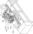
Fig. 1 is a schematic structural view of the reaming machine for forklift wheel carriers of the present invention.
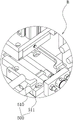
Fig. 2 is an enlarged view of a portion a in fig. 1.
Fig. 3 is the partial structure schematic diagram of the forklift truck wheel carrier reaming machine of the utility model.
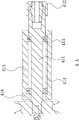
Fig. 4 is an enlarged view of a portion B in fig. 3.
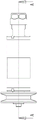
Fig. 5 is a schematic view of a reaming tool according to a preferred embodiment of the present invention.
Fig. 6 is a schematic view of the structure shown in fig. 5 from another view angle.
Fig. 7 is a sectional view a-a of fig. 6.
In the figure, 100, a rack; 110. a support bracket; 111. a processing platform; 120. a discharging cylinder; 130. a discharge plate; 200. forklift wheel carriers; 210. a shaft hole; 300. a limiting component; 310. a limiting bracket; 320. a limiting cylinder; 330. a limiting block; 400. a reaming assembly; 410. a reaming tool; 411. a drive shaft; 412. a collet nut; 413. a bearing; 414. a space ring; 415. a copper sleeve; 416. an end cap; 420. a substrate; 430. a reaming motor; 440. a pulley structure; 450. a load bearing support; 460. a tension wheel; 470. a brush; 480. a steel wire brush; 490. a main shaft base; 500. a positioning assembly; 510. positioning blocks; 511. positioning holes; 600. a sliding component; 610. a slipping cylinder; 620. a slider; 630. a slide rail.
Detailed Description
The following are specific embodiments of the present invention and the accompanying drawings are used to further describe the technical solution of the present invention, but the present invention is not limited to these embodiments.
It should be noted that all the directional indicators (such as upper, lower, left, right, front, rear … …) in the embodiments of the present invention are only used to explain the relative position relationship between the components, the motion situation, etc. in a specific posture (as shown in the drawings), and if the specific posture is changed, the directional indicator is changed accordingly.
As shown in fig. 1 to 7, the utility model provides a pair of fork truck wheel carrier reaming machine, include:
the forklift truck comprises a rack 100 and a supporting bracket 110 arranged on the rack 100, wherein a processing platform 111 for placing a forklift truck carrier 200 is arranged on the supporting bracket 110, and a limiting component 300 for preventing the forklift truck carrier 200 from moving or rotating in the processing process is arranged at a position corresponding to the processing platform 111;
and the reaming assembly 400 is movably installed on the frame 100, wherein the reaming assembly 400 comprises a plurality of reaming tools 410, and the position of each reaming tool 410 corresponds to the position of the shaft hole 210 on the forklift truck frame 200 one by one.
When the forklift truck frame 200 needs to be reamed, the forklift truck frame 200 is firstly placed on the processing platform 111, then the forklift truck frame 200 is fixed on the processing platform 111 through the limiting component 300 to prevent the forklift truck frame 200 from moving or rotating, at the moment, the shaft holes 210 in the forklift truck frame 200 and the reaming tools 410 complete the one-to-one corresponding position relationship, then the reaming component 400 is driven to be close to the supporting bracket 110, so that the reaming tools 410 are correspondingly inserted into the shaft holes 210 to perform reaming work, after the processing is completed, the reaming component 400 is far away from the supporting bracket 110, so that the reaming tools 410 are withdrawn from the shaft holes 210, finally the limiting component 300 releases the fixation of the forklift truck frame 200, and a worker can take down the processed forklift truck frame 200 from the processing platform 111.
The utility model provides a pair of fork truck wheel carrier reaming machine accomplishes the reaming processing of each shaft hole 210 on the fork truck wheel carrier 200 through reaming subassembly 400, has guaranteed the uniformity of shaft hole 210 processing on the one hand, and on the other hand has improved work efficiency, has reduced corresponding working strength.
It should be noted that the forklift truck frame 200 is generally arranged in an H-shaped structure, i.e. a symmetrical structure, and therefore, the axle holes 210 are arranged on both sides of the forklift truck frame 200, and in order to further improve the processing efficiency of the axle holes 210, the two sides of the forklift truck frame 200 can be respectively and correspondingly provided with the hinge hole assemblies 400, so that the axle holes 210 on both sides of the forklift truck frame 200 can be synchronously processed, and the processing time is further saved.
Preferably, the limiting assembly 300 fixes the forklift truck 200 on the processing platform 111 from top to bottom.
Further, the limiting assembly 300 comprises a limiting bracket 310 installed on the processing platform 111, and a limiting cylinder 320 is installed on the limiting bracket 310, wherein the output end of the limiting cylinder 320 is connected with a limiting block 330. The limiting cylinder 320 drives the limiting block 330 to move in the direction close to the processing platform 111, so that the forklift truck 200 is positively pressed on the processing platform 111.
It should be noted that the limiting component 300 can achieve the vertical limiting of the forklift truck frame 200, but cannot ensure the horizontal limiting of the forklift truck frame 200, so that the situation that the forklift truck frame 200 horizontally deviates before being compressed by the limiting component 300 is easily caused, on one hand, the limiting component 300 cannot positively compress the forklift truck frame 200, and a "bias" state exists, on the other hand, the reaming tool 410 on one side of the forklift truck frame 200 cannot completely penetrate through the axle hole 210, and further, the reaming process in the axle hole 210 cannot be completed. Therefore, based on the above defects, the positioning assembly 500 is arranged on the processing platform 111, and the forklift truck wheel carrier 200 is limited in the horizontal direction by the positioning assembly 500, so that the limiting assembly 300 can be positively pressed without deviation.
Preferably, the positioning assembly 500 includes positioning blocks 510 oppositely disposed, and the positioning blocks 510 are connected to the processing platform 111 by fasteners, wherein the two positioning blocks 510 are used to clamp the forklift truck 200. In addition, the positioning block 510 has a certain thickness, so that the forklift truck frame 200 and the positioning block 510 are in clamping fit, and the forklift truck frame 200 is limited in the horizontal direction.
It should be noted that, since the forklift trucks 200 corresponding to each forklift truck have slightly different sizes although the forklift trucks have the same or different shapes, in order to improve the versatility of the reaming machine, the positioning holes 511 of the positioning blocks 510 connected to the processing platform 111 may be provided with oblong holes, so that the relative distance between the two positioning blocks 510 is adjustable.
Preferably, the movement of the hinge hole assembly 400 toward or away from the support bracket 110 may be accomplished by the glide assembly 600.
Further preferably, the sliding assembly 600 includes a sliding cylinder 610 mounted on the frame 100, and the sliding cylinder 610 is connected to the hinge hole assembly 400, wherein the hinge hole assembly 400 is provided with a sliding block 620, and the sliding block 620 is slidably engaged with a sliding rail 630 mounted on the frame 100.
It is worth mentioning that, in order to reduce the lateral width of the reaming machine and improve the space utilization on the frame 100, the slide cylinder 610 may be installed in a hollowed-out area of the support bracket 110, and the existence of the hollowed-out area enables the entire support bracket 110 to form a structure similar to a square.
Preferably, the reaming assembly 400 includes a base plate 420 coupled to a slider 620, and a reaming motor 430 coupled to the base plate 420, wherein the reaming tool 410 is coupled to the output of the reaming motor 430 via a pulley structure 440.
The plurality of reaming tools 410 are driven to operate by the same reaming motor 430, thereby reducing the equipment cost of the reaming machine and ensuring the synchronism of the operations of the plurality of reaming tools 410.
It should be noted that the belt wheel at the end of each belt wheel structure 440 connected to the output end of the hinge motor 430 is integrally disposed, that is, the belt wheels connected to the output end of the hinge motor 430 in the plurality of belt wheel structures 440 are the same, wherein the belt wheel is provided with a plurality of coaxial grooves for connecting belts at different positions. And such a structural arrangement further ensures the synchronicity of the operation of the reaming tools 410.
It is further preferred that a carrier bracket 450 is attached to the base plate 420, and the plurality of reaming tools 410 are mounted to the carrier bracket 450 by a spindle base 490, wherein a tensioner 460 attached to a belt of one of the pulleys is attached to the carrier bracket 450.
Preferably, the reaming tool 410 comprises a driving shaft 411, one end of the driving shaft 411 is connected with a belt pulley connected with a belt through a fastener, the other end of the driving shaft 411 is connected with a brush 470 or a wire brush 480 and is locked through a collet nut 412, wherein two bearings 413 are nested on the driving shaft 411 between the belt pulley and the collet nut 412, a spacer ring 414 is arranged between the two bearings 413, a copper sleeve 415 is nested on the spacer ring 414, and an end cover 416 is nested at each end of the copper sleeve 415.
In this embodiment, the brush 470 or the wire brush 480 is detachably connected to the driving shaft 411, so that an operator can replace the brush according to a machining process required by the corresponding shaft hole 210 of the forklift truck wheel carrier 200, which is convenient to operate. In addition, the brush 470 is adopted to realize flexible reaming, and the knife edge is prevented from being broken when the reamer is adopted for reaming.
Preferably, the processing platform 111 is further provided with a discharging cylinder 120 and a discharging plate 130 corresponding to the discharging cylinder 120 and mounted on the processing platform 111, wherein after the shaft hole 210 of the forklift truck carrier 200 is processed, the forklift truck carrier 200 is pushed by the discharging cylinder 120 to enter the discharging plate 130, so that the automatic discharging of the forklift truck carrier 200 is realized, and the working efficiency is further improved.
It should be noted that the descriptions in the present application as to "first", "second", "a", etc. are for descriptive purposes only and are not to be construed as indicating or implying relative importance or implying any indication of the number of technical features indicated. Thus, a feature defined as "first" or "second" may explicitly or implicitly include at least one of the feature. In the description of the present invention, "a plurality" means at least two, e.g., two, three, etc., unless explicitly defined otherwise. The terms "connected", "fixed", and the like are to be construed broadly, and for example, "fixed" may be a fixed connection, a detachable connection, or an integral part; can be mechanically or electrically connected; they may be directly connected or indirectly connected through intervening media, or they may be interconnected within two elements or in a relationship where two elements interact with each other unless otherwise specifically limited. The specific meaning of the above terms in the present invention can be understood according to specific situations by those skilled in the art.
In addition, the technical solutions of the embodiments of the present invention can be combined with each other, but it is necessary to use a person skilled in the art to realize the basis, and when the technical solutions are combined and contradictory to each other or cannot be realized, the combination of the technical solutions should not exist, and is not within the protection scope of the present invention.
The specific embodiments described herein are merely illustrative of the spirit of the invention. Various modifications, additions and substitutions may be made by those skilled in the art to the specific embodiments described without departing from the spirit of the invention or exceeding the scope of the invention as defined in the accompanying claims.
Claims (10)
1. A fork truck wheel carrier reaming machine, characterized in that includes:
the device comprises a rack, wherein a support bracket is arranged on the rack, a processing platform for placing a forklift wheel carrier is arranged on the support bracket, and a limiting component for preventing the forklift wheel carrier from moving or rotating in the processing process is arranged at a position corresponding to the processing platform;
and the reaming assembly is movably arranged on the rack and comprises a plurality of reaming tools, and the position of each reaming tool corresponds to the position of the shaft hole on the forklift wheel carrier one by one.
2. The forklift truck wheel carrier reaming machine according to claim 1, wherein the reaming assembly is movable toward or away from the support bracket by a sliding assembly, wherein the sliding assembly comprises a sliding cylinder, and the sliding cylinder is connected with the reaming assembly.
3. The forklift truck carriage reaming machine of claim 1, wherein the reaming assembly comprises a base plate, and a reaming motor is connected to the base plate, wherein the output end of the reaming motor is connected to the reaming tool through a pulley structure.
4. The forklift truck wheel carrier reaming machine according to claim 3, wherein a plurality of pulleys are structurally integrated with the pulleys connected to the output end of the reaming motor.
5. The forklift truck wheel carrier reaming machine according to claim 3, wherein a carrying bracket is connected to the base plate, and a plurality of reaming tools are mounted on the carrying bracket through the spindle base, wherein a tensioning wheel connected to a belt of one of the pulleys is connected to the carrying bracket.
6. The forklift truck wheel carrier reaming machine according to claim 3, wherein the reaming tool comprises a driving shaft, one end of the driving shaft is connected with a belt wheel connected with a belt through a fastener, the other end of the driving shaft is connected with a hairbrush or a wire brush and locked through a collet nut, wherein two bearings are nested on the driving shaft between the belt wheel and the collet nut, a spacer ring is arranged between the two bearings, a copper sleeve is nested on the spacer ring, and an end cover is nested at each end of the copper sleeve.
7. The reaming machine for the wheel carrier of the forklift as claimed in any one of claims 1 to 6, wherein the limiting component fixes the wheel carrier of the forklift on the processing platform from top to bottom and comprises a limiting bracket mounted on the processing platform, wherein a limiting cylinder is mounted on the limiting bracket, and the output end of the limiting cylinder is connected with a limiting block.
8. The reaming machine for the wheel carrier of the forklift according to any one of claims 1 to 6, wherein the processing platform is provided with a positioning assembly, the positioning assembly comprises positioning blocks which are oppositely arranged, the positioning blocks are connected to the processing platform through fasteners, and the clamping of the wheel carrier of the forklift is realized through the two positioning blocks.
9. The reaming machine for the wheel carrier of the forklift truck as claimed in claim 8, wherein the positioning hole of the positioning block connected to the processing platform is provided with a long circular hole.
10. The forklift truck wheel carrier reaming machine according to any one of claims 1 to 6, wherein a discharging cylinder and a discharging plate corresponding to the discharging cylinder and mounted on the processing platform are further mounted on the processing platform.
Priority Applications (1)
| Application Number | Priority Date | Filing Date | Title |
|---|---|---|---|
| CN202220279036.8U CN217044871U (en) | 2022-02-11 | 2022-02-11 | Forklift truck wheel carrier reaming machine |
Applications Claiming Priority (1)
| Application Number | Priority Date | Filing Date | Title |
|---|---|---|---|
| CN202220279036.8U CN217044871U (en) | 2022-02-11 | 2022-02-11 | Forklift truck wheel carrier reaming machine |
Publications (1)
| Publication Number | Publication Date |
|---|---|
| CN217044871U true CN217044871U (en) | 2022-07-26 |
Family
ID=82485940
Family Applications (1)
| Application Number | Title | Priority Date | Filing Date |
|---|---|---|---|
| CN202220279036.8U Active CN217044871U (en) | 2022-02-11 | 2022-02-11 | Forklift truck wheel carrier reaming machine |
Country Status (1)
| Country | Link |
|---|---|
| CN (1) | CN217044871U (en) |
-
2022
- 2022-02-11 CN CN202220279036.8U patent/CN217044871U/en active Active
Similar Documents
| Publication | Publication Date | Title |
|---|---|---|
| CN107971682B (en) | Quick clamp replacing device | |
| CN111038944A (en) | AGV material tray positioner | |
| CN211545164U (en) | Feeding device and processing equipment | |
| CN112122850B (en) | Welding tool and welding method for pallet truck cargo fork leg assembly | |
| CN211495528U (en) | AGV material tray positioner | |
| CN217044871U (en) | Forklift truck wheel carrier reaming machine | |
| CN209986568U (en) | Working table | |
| CN219425978U (en) | Welding and repair welding alternating type industrial welding workstation | |
| CN214161845U (en) | Turnover tool | |
| CN212793769U (en) | Turnover polishing blanking system of white body side wall welding workstation | |
| CN213497151U (en) | Welding equipment | |
| CN210359360U (en) | Double-shaft drilling machine tool | |
| CN212047647U (en) | Transfer trolley for automobile door plate and production line with transfer trolley | |
| CN210998789U (en) | Clamping mechanism of automatic centering for arm | |
| CN219339494U (en) | Industrial robot floor truck | |
| CN220393226U (en) | Liftable transport frame for machine tool machining materials | |
| CN216888636U (en) | Trolley used for matching automobile production welding workshop adjusting line with AGV | |
| CN206898692U (en) | A kind of car body welding producing line flexibility switching device | |
| CN220312468U (en) | Quick clamp replacing device | |
| CN214291655U (en) | Welding fixture structure for inner plate assembly of automobile back door | |
| CN112207606B (en) | Channel-section steel processing transfer device, processing device and production line | |
| CN212122333U (en) | Automatic assembly machine | |
| CN217344072U (en) | Unloader and laser marking equipment | |
| CN215160616U (en) | Heavy-load four-way shuttle synchronous lifting mechanism | |
| CN211545147U (en) | Automatic sorting machine and stacker crane |
Legal Events
| Date | Code | Title | Description |
|---|---|---|---|
| GR01 | Patent grant | ||
| GR01 | Patent grant |