CN217021311U - Cutting jig - Google Patents
Cutting jig Download PDFInfo
- Publication number
- CN217021311U CN217021311U CN202220087101.7U CN202220087101U CN217021311U CN 217021311 U CN217021311 U CN 217021311U CN 202220087101 U CN202220087101 U CN 202220087101U CN 217021311 U CN217021311 U CN 217021311U
- Authority
- CN
- China
- Prior art keywords
- assembly
- cut
- lower die
- piece
- punch
- Prior art date
- Legal status (The legal status is an assumption and is not a legal conclusion. Google has not performed a legal analysis and makes no representation as to the accuracy of the status listed.)
- Active
Links
Images


Abstract
A cutting jig is used for cutting a piece to be cut, and the piece to be cut comprises a workpiece and a cutting portion which are connected with each other. The cutting jig comprises a lower die assembly, an upper die assembly and a driving assembly, wherein the upper die assembly comprises a first movable assembly, a second movable assembly and an elastic piece, the lower die assembly and the second movable assembly jointly fix a piece to be cut, and under the driving action of the driving assembly and the elastic action of the elastic piece, a punch in the first movable assembly continuously moves towards the piece to be cut and removes a cut part; the compression amount of the elastic piece can be designed according to the required cutting depth, so that the part of the piece to be cut, which does not need to be removed, is prevented from being cut, and the workpiece is prevented from being damaged; the cutting jig replaces manual operation, and the cutting is clean and efficient.
Description
Technical Field
The application relates to the tool field, especially relates to a tool cuts.
Background
In the process of manufacturing the workpiece by adopting the injection molding process, the injection molding is carried out through the injection port to mold the workpiece, so that the surface of the molded workpiece is connected with an excessive part (a cut-off part) formed at the injection port, and the cut-off part needs to be removed.
The process of removing the cut-out portion of the piece to be cut 200' generally includes manual trimming and cutting. When the material is cut manually, please refer to fig. 1, when the size of the glue injection port is small, the glue injection port is difficult to be cut off completely, and burrs are easy to be left; and the efficiency is low due to manual material shearing. Referring to fig. 2, in a conventional cutting process, the workpiece 210 ' is directly penetrated from two opposite surfaces thereof, and for some shaped workpieces 210 ' (e.g., having a step 230 '), the cut-out portion 220 ' is removed and simultaneously the step 230 ' on the workpiece is cut, thereby damaging the workpiece.
SUMMERY OF THE UTILITY MODEL
In view of the above, it is desirable to provide a cutting jig which can cut a workpiece cleanly and efficiently without damaging the workpiece.
A cutting jig is used for cutting a piece to be cut, and the piece to be cut comprises a workpiece and a cutting portion which are connected with each other. The cutting jig comprises: lower mould subassembly, last mould subassembly and drive assembly. The lower die assembly comprises a supporting piece, the supporting piece comprises a first concave part and a second concave part which are communicated with each other, the first concave part is used for accommodating a workpiece, and the second concave part is used for accommodating the cut-off part; the upper die assembly comprises a first movable assembly, an elastic piece and a second movable assembly, the elastic piece is elastically connected with the first movable assembly and the second movable assembly, and the second movable assembly is positioned at one side close to the lower die assembly; the first movable member includes a punch extending toward the support; the driving component is connected with and can drive the lower die component and/or the first movable component; the workpiece to be cut is placed in the supporting piece, the driving assembly drives the upper die assembly and/or the lower die assembly to move relatively, the second movable assembly and the supporting piece fix the workpiece, the elastic piece deforms, and the punch is driven to move towards the workpiece to be cut until the cut part is cut.
In some embodiments, the support further comprises a third recess, the third recess in communication with the first recess.
In some embodiments, the lower die assembly further comprises a lower die holder, and the support is disposed on a surface of the lower die holder facing the upper die assembly.
In some embodiments, the lower die holder is provided with a guide sleeve, the guide sleeve is formed by a surface depression of the lower die holder carrying the support, and the guide sleeve is exposed on the support.
In some embodiments, the lower die assembly further comprises a limiting post located on the surface of the lower die base facing the upper die assembly and protruding towards the upper die assembly.
In some embodiments, the first movable assembly comprises an upper die base, a clamping plate, a guide pillar and a punch, and the upper die base, the clamping plate, the guide pillar and the punch are fixedly connected; the clamp plate is fixed on the surface of the upper die base facing the lower die assembly, the guide pillar is fixed on the upper die base and faces the guide sleeve, and the punch is fixed on the upper die base or the clamp plate.
In some embodiments, the punch includes a first face and a second face, the first face and the second face joining to form a cutting edge, the second face and the second face forming an acute angle therebetween.
In some embodiments, the second movable assembly includes a back plate and a pressing plate, the pressing plate is disposed on a side of the clamping plate away from the upper mold assembly, and the back plate is movably connected to the clamping plate through an elastic member.
In some embodiments, a first through hole is formed in the back plate, a second through hole is formed in the pressing plate, the first through hole is communicated with the second through hole, and the punch can be arranged in the first through hole and the second through hole in a penetrating manner.
In some embodiments, at least one of the first recess and the second recess is a groove.
The cutting jig provided by the application replaces manual operation, so that the cutting is clean, burrs are not easy to leave, and the efficiency is high; in addition, the cutting jig comprises a lower die assembly, an upper die assembly and a driving assembly, wherein the upper die assembly comprises a first movable assembly, a second movable assembly and an elastic piece, the lower die assembly and the second movable assembly jointly fix the piece to be cut, and under the driving action of the driving assembly and the elastic action of the elastic piece, a punch in the first movable assembly continuously moves towards the piece to be cut and removes a cut part; the compression amount of the elastic piece can be designed according to the required cutting depth, so that the part of the piece to be cut, which does not need to be removed, is prevented from being cut, and the workpiece is prevented from being damaged.
Drawings
Fig. 1 is a schematic partial structural view of a to-be-cut part provided in the related art of the present application.
Fig. 2 is a schematic structural view of a damaged workpiece while a cut-off portion is removed by a cutting process according to the related art of the present application.
Fig. 3 is a schematic front view of a cutting tool according to an embodiment of the present application.
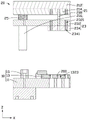
Fig. 4 is a schematic overall structure diagram of the cutting jig provided in the embodiment of the present application, including a lower die assembly and an upper die assembly.
Fig. 5 is a schematic view of the overall structure of the supporting member in fig. 4.
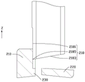
Fig. 6 is a schematic cross-sectional view of a punch provided in an embodiment of the present application before cutting off a member to be cut.
Fig. 7 is a schematic cross-sectional view of a punch provided in an embodiment of the present application during cutting of a to-be-cut member.
Fig. 8 is a schematic cross-sectional view of a cutting jig provided in an embodiment of the present application before a to-be-cut piece is cut off.
Fig. 9 is a schematic cross-sectional view of a pressing plate and a supporting member just contacting when a cutting tool provided by the embodiment of the application cuts off a member to be cut.
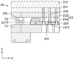
Fig. 10 is a schematic cross-sectional view of a cutting jig provided in an embodiment of the present application after a cutting portion is cut by a punch when the cutting jig cuts a member to be cut.
Description of the main elements


The following detailed description will further illustrate the present application in conjunction with the above-described figures.
Detailed Description
In order that the above objects, features and advantages of the present application can be more clearly understood, a detailed description of the present application will be made below with reference to the accompanying drawings and detailed description. In addition, the embodiments and features of the embodiments of the present application may be combined with each other without conflict. In the following description, numerous specific details are set forth to provide a thorough understanding of the present application, and the described embodiments are merely a subset of the embodiments of the present application, rather than all embodiments.
Unless defined otherwise, all technical and scientific terms used herein have the same meaning as commonly understood by one of ordinary skill in the art to which this application belongs. The terminology used herein in the description of the present application is for the purpose of describing particular embodiments only and is not intended to be limiting of the application. As used herein, the term "and/or" includes all and any combination of one or more of the associated listed items.
In various embodiments of the present application, for convenience in description and not limitation, the term "coupled" as used in the specification and claims of the present application is not limited to physical or mechanical connections, either direct or indirect. "upper", "lower", "above", "below", "left", "right", and the like are used merely to indicate relative positional relationships, and when the absolute position of the object being described is changed, the relative positional relationships are changed accordingly.
Referring to fig. 3, the present embodiment provides a cutting jig 100, and the cutting jig 100 is used for cutting a to-be-cut piece 200. The member to be cut 200 includes the workpiece 210 and the cut portion 220 connected to each other, and the specific type of the workpiece 210 is not limited, and the material of the cut portion 220 is not limited depending on the specific type of product. In the present embodiment, the workpiece 210 is taken as a lens holder, the cut-out portion 220 is taken as a glue body, and the cut-out portion 220 is a corresponding portion formed at the glue injection port in the glue injection process.
Referring to fig. 3 again, fig. 3 is a front view of the cutting jig 100. The cutting jig 100 includes a lower die assembly 10, an upper die assembly 20, and a drive assembly 30. The lower die assembly 10 supports the part to be cut 200, the upper die assembly 20 includes a punch 218, the punch 218 faces the part to be cut 200, and the drive assembly 30 drives the upper die assembly 20 and/or the lower die assembly 10 to move relatively so that the punch 218 cuts the cut portion 220 of the part to be cut 200.
Referring to fig. 4, for convenience of reference, the driving assembly 30 and other supporting structures are omitted from fig. 4, and fig. 4 is a schematic view of the overall structure of the lower mold assembly 10 and the upper mold assembly 20 of fig. 3. The lower die assembly 10 includes a lower die base 11 and a support 13. The lower die holder 11 is a block, the lower die holder 11 has a bearing surface 112, the supporting member 13 is fixed on the bearing surface 112, and the bearing surface 112 is parallel to the horizontal plane when the cutting jig 100 is in use.
For convenience of illustration, the plane of the carrying surface 112 is defined as an XY plane, a direction perpendicular to the XY plane is defined as a Z-axis direction, the XY plane is defined by an X-axis direction and a Y-axis direction perpendicular to each other, and the X-axis direction, the Y-axis direction and the Z-axis direction are perpendicular to each other.
The lower die holder 11 has a guide sleeve 114, and the guide sleeve 114 is recessed from the bearing surface 112 in the Z-axis direction toward the surface facing away from the support 13. The number of the guide sleeves 114 may be one or more, in this embodiment, the number of the guide sleeves 114 is four, and the guide sleeves 114 are respectively located at four corner positions of the lower die holder 11, and the position of the guide sleeves 114 is not overlapped with the surface of the lower die holder 11 carrying the support 13, that is, when the support 13 is fixed on the lower die holder 11, the guide sleeves 114 are exposed to the support 13 along the Z-axis direction. Guide sleeve 114 is used to guide the movement of upper die assembly 20.
Referring to fig. 5, the supporting member 13 is a block. The supporting member 13 includes a receiving portion 132, and the receiving portion 132 is used for receiving the member to be cut 200. Specifically, the accommodating portion 132 includes a first recess 1321 and a second recess 1323 that communicate with each other. The first recess 1321 is used for accommodating the workpiece 210, the second recess 1323 is used for accommodating the cut-out portion 220, and the specific shapes of the first recess 1321 and the second recess 1323 are set according to the formation of the piece to be cut-out 200.
At least one of the first recess 1321 and the second recess 1323 is a groove to satisfy a function of supporting the member to be cut 200. In this embodiment, the first recess 1321 is a groove, and the second recess 1323 is a through hole, that is, the first recess 1321 is formed by a surface of the support 13 away from the lower die holder 11 and recessed toward the lower die holder 11 along the Z-axis direction, and the second recess 1323 penetrates through two opposite surfaces of the support 13 along the Z-axis direction. The first recess 1321 and the second recess 1323 are connected to each other in the XY plane, that is, the second recess 1323 may be formed by an inner wall forming the first recess 1321 being recessed in the X-axis direction and/or the Y-axis direction. When the piece 200 to be cut is accommodated in the accommodating portion 132, the first recess 1321 is a groove capable of supporting the piece 200 to be cut, and the second recess 1323 is a through hole for allowing the cut portion 220 to directly fall from the through hole when the piece 200 to be cut is cut and the cut portion 220 is separated from the workpiece 210. Wherein, when the member to be cut 200 is placed in the receiving portion 132, a portion of the member to be cut 200 protrudes from a surface of the support member 13 facing the upper die assembly 20 in the Z-axis direction, so that the upper die assembly 20 and the support member 13 fix the member to be cut 200 during cutting.
In other embodiments, the first recess 1321 and the second recess 1323 may be both grooves, that is, the first recess 1321 and the second recess 1323 are formed by recessing the surface of the support 13 facing away from the lower die holder 11 in the direction of the lower die holder 11 along the Z-axis direction. When the to-be-cut piece 200 is accommodated in the accommodating portion 132, the first recessed portion 1321 and the second recessed portion 1323 are both grooves capable of supporting the to-be-cut piece 200.
In other embodiments, the first recess 1321 is a through hole, the second recess 1323 is a groove, and the second recess 1323 supports the to-be-cut piece 200 when the to-be-cut piece 200 is received in the receiving portion 132.
In this embodiment, each first recess 1321 is connected to two second recesses 1323, and the support member 13 is provided with 8 mutually independent first recesses 1321 and second recesses 1323 for accommodating the pieces to be cut 200, that is, 8 pieces to be cut 200 can be cut at the same time, thereby improving the processing efficiency.
Referring to fig. 5 again, the supporting member 13 further includes a third recess 134, and the third recess 134 is communicated with the first recess 1321. In some embodiments, the third recess 134 may be a groove, and the third recess 134 is formed by recessing the surface of the support 13 facing away from the lower die holder 11 in the direction of the Z-axis toward the lower die holder 11; in other embodiments, the third recess 134 may be a through hole, and the third recess 134 penetrates through the two opposite surfaces of the supporting member 13 along the Z-axis direction. When the to-be-cut-off member 200 is placed in the first recess 1321 and the second recess 1323, the work 210 of the to-be-cut-off member 200 passes through the third recess 134. The third recess 134 is provided to facilitate access to the to-be-cut piece 200.
Referring to fig. 4 again, the upper mold assembly 20 includes a first movable assembly 21, a second movable assembly 23, and an elastic member 25, wherein the first movable assembly 21 and the second movable assembly 23 are spaced apart from each other by the elastic member 25 and are movably connected to each other.
The first movable assembly 21 includes an upper die base 212, a clamping plate 214, a guide post 216 and a punch 218, and the upper die base 212, the clamping plate 214, the guide post 216 and the punch 218 are fixedly connected. The upper die holder 212 and the clamping plate 214 are block-shaped, and the clamping plate 214 is fixed to a surface of the upper die holder 212 facing the lower die assembly 10. The guide post 216 is fixed to a surface of the upper die base 212 facing the lower die assembly 10, the guide post 216 is a columnar shape, the guide post 216 extends toward the lower die assembly 10 along the Z-axis direction, and the guide post 216 penetrates the guide post 216. The number of the guide posts 216 is the same as that of the guide sleeves 114, and the positions of the guide posts 216 and the positions of the guide sleeves 114 are arranged correspondingly, that is, the projection of the guide posts 216 along the Z-axis direction is located in the guide sleeves 114, and when the upper die assembly 20 and the lower die assembly 10 move relatively, the guide sleeves 114 are used for accommodating the guide posts 216 and guiding the movement of the upper die assembly 20 relative to the lower die assembly 10 along the Z-axis direction.
A punch 218 is fixed to the upper die base 212 or the clamping plate 214, and the punch 218 extends in the Z-axis direction toward the lower die assembly 10. The mounting positions and the number of the punches 218 are related to the areas to be cut and the number of the to-be-cut pieces 200, and in the present embodiment, one to-be-cut piece 200 mounts two punches 218.
Referring also to FIG. 6, in some embodiments, the punch 218 includes a first surface 2181 and a second surface 2183, and a line connecting the first surface 2181 and the second surface 2183 is a blade 2185 of the punch 218. The first face 2181 is parallel to the Z-axis direction, the second face 2183 is a surface of the punch 218 facing the lower die assembly 10, and the second face 2183 and the first face 2181 form an included angle θ, the included angle θ is an acute angle, and the included angle θ ranges from 45 ° to 89 °. Referring to fig. 6 and 7, when the cutting edge 2185 of the punch 218 cuts the to-be-cut part 200, the second surface 2183 is inclined compared with the to-be-cut part 200, and in the process that the cutting edge 2185 starts to contact the to-be-cut part 200 until the cutting part 220 is completely separated from the workpiece 210, the second surface 2183 gradually contacts the to-be-cut part 220 and abuts against the cutting part 220, so that the cut cutting part 220 is smoothly separated from the workpiece 210 and falls down. In this embodiment, the cutting portion 220 is cut by the cutting edge 2185 of the punch 218, no cutting edge is provided in the lower die assembly 10, and no other sharp component collides with the punch 218 during the cutting process of the punch 218, so that the service life of the punch 218 can be prolonged.
Referring to fig. 4 again, the second movable assembly 23 includes a back plate 232 and a pressing plate 234, wherein the back plate 232 and the pressing plate 234 are fixedly connected. The pressing plate 234 is disposed on a side of the clamping plate 214 facing away from the upper mold assembly 20, and the back plate 232 is movably connected to the clamping plate 214 through the elastic member 25. The guide posts 216 also pass through the back plate 232, and the back plate 232 can be displaced relative to the guide posts 216 along the extending direction of the guide posts 216. The pressing plate 234 is disposed on the surface of the back plate 232 facing the lower mold assembly 10, and when the upper mold assembly 20 moves towards the lower mold assembly 10, the pressing plate 234 covers the surface of the supporting member 13, so as to limit the to-be-cut piece 200 in the supporting member 13 for easy cutting.
The back plate 232 is provided with a first through hole 2321, the pressure plate 234 is provided with a second through hole 2341, the first through hole 2321 is communicated with the second through hole 2341, that is, along the Z-axis direction, the projections of the first through hole 2321 and the second through hole 2341 coincide. The positions of the first through hole 2321 and the second through hole 2341 correspond to the position of the punch 218, and when the pressure plate 234 is not in contact with the supporting member 13, the punch 218 is accommodated in the first through hole 2321 and the second through hole 2341; after the pressing plate 234 is in contact with the supporting member 13 and the pressing force is continuously applied, the clamping plate 214 compresses the elastic member 25 to deform the elastic member 25, and the punch 218 penetrates through the first through hole 2321 and the second through hole 2341 and moves towards the member to be cut 200, so that the cut portion 220 on the member to be cut 200 is cut.
The elastic member 25 can be deformed by external force, and can recover the deformation after losing the external force, such as a spring, an elastic polymer material (e.g. polyimide, PI), and the like. In the embodiment, the elastic member 25 is a spring, the spring is sleeved on the guide post 216 between the clamping plate 214 and the back plate 232, the spring is partially accommodated in the clamping plate 214 and the back plate 232, and the maximum compression amount of the spring is the distance between the clamping plate 214 and the back plate 232 when the spring is in an uncompressed state. In other embodiments, the number and specific arrangement positions of the elastic members 25 are not limited.
The maximum compression of the resilient member 25 can be set according to the amount of the member to be cut 200 to be cut and the position of the punch 218 in the back plate 232 and the pressing plate 234, the compression of the resilient member 25 is equal to the displacement distance of the punch 218 compared with the second movable assembly 23, and the maximum compression of the resilient member 25 is equal to the sum of the distance between the punch 218 and the pressing plate 234 toward the surface of the support 13 and the depth of the member to be cut 200 to be cut in the Z-axis direction. By controlling the maximum amount of compression of the elastic member 25, that is, when the workpiece 210 has the step 230 projecting in the X-axis direction and/or the Y-axis direction, the punch 218 cannot move in the Z-axis direction after the cut-away portion 220 is removed, so that the step 230 on the workpiece 210 can be prevented from being cut.
A drive assembly 30 is coupled to upper mold assembly 20 and/or lower mold assembly 10 for driving upper mold assembly 20 and/or lower mold assembly 10 in a relative motion along the Z-axis. In this embodiment, the driving assembly 30 is connected to the upper mold assembly 20, and the driving assembly 30 can drive the upper mold assembly 20 to move toward the lower mold assembly 10. The drive assembly 30 may be a pneumatic cylinder.
The present application is described below with reference to a specific excision process.
Referring to fig. 8, in the initial state, the upper mold assembly 20 and the lower mold assembly 10 are spaced apart, the to-be-cut piece 200 is disposed in the first recess 1321 and the second recess 1323 of the supporting member 13, and the cut portion 220 of the to-be-cut piece 200 is suspended in the second recess 1323 (through hole). The punch 218 is located in the first through hole 2321 and the second through hole 2341, i.e., the punch 218 does not protrude from the surface of the platen 234 facing the lower die assembly 10.
Referring to fig. 9, power is turned on to the driving assembly 30 to operate the driving assembly 30, and the driving assembly 30 drives the upper mold assembly 20 to move toward the lower mold assembly 10. Wherein the driving assembly 30 is connected to the upper mold assembly 20, the driving assembly 30 drives the upper mold base 212 to move towards the lower mold assembly 10 along the Z-axis direction, and the first movable assembly 21 including the upper mold assembly 20 and the second movable assembly 23 connected to the first movable assembly 21 move towards the lower mold assembly 10 synchronously until the pressing plate 234 in the second movable assembly 23 contacts with the support 13 of the lower mold assembly 10. At this point, the elastic element 25 connecting the first movable element 21 and the second movable element 23 is at the critical point of being uncompressed but about to be compressed; in addition, the cover plate covers the supporting member 13 to fix the member to be cut 200 in the first recess 1321 and the second recess 1323.
Referring to fig. 10, drive assembly 30 continues to drive upper die assembly 20 toward lower die assembly 10. Wherein the second movable assembly 23 is in contact with the lower die assembly 10 and does not move any further; the first movable assembly 21 elastically connected to the second movable assembly 23 continues to move toward the lower die assembly 10 in the Z-axis direction by the deformation of the elastic member 25. At this time, the clamping plate 214 contacts the back plate 232, the elastic member 25 is completely retracted in the clamping plate 214 and the back plate 232, and the punch 218 penetrates the first through hole 2321 and the second through hole 2341 and protrudes from the surface of the pressing plate 234 facing the lower die assembly 10, so as to cut the to-be-cut member 200 (see also fig. 7).
Referring to fig. 4 again, the lower mold assembly 10 may further include a limiting post 15, the limiting post 15 is disposed on a surface of the lower mold base 11 facing the upper mold assembly 20, and the limiting post 15 extends toward the upper mold assembly 20 along the Z-axis direction. During the movement of the upper mold assembly 20 toward the lower mold assembly 10, the limiting columns 15 are used to limit the maximum distance that the upper mold assembly 20 moves toward the lower mold assembly 10, and prevent the workpiece 210 from being damaged or deformed by the second movable assembly 23 of the upper mold assembly 20 pressing the workpiece 210 over the upper mold assembly 20.
The cutting jig 100 provided by the application replaces manual operation, so that the cutting is clean, burrs are not easy to remain, and the efficiency is high; in addition, the cutting jig 100 provided by the application comprises a lower die assembly 10, an upper die assembly 20 and a driving assembly 30, wherein the upper die assembly 20 comprises a first movable assembly 21, a second movable assembly 23 and an elastic member 25, the lower die assembly 10 and the second movable assembly 23 jointly fix the to-be-cut part 200, and under the driving action of the driving assembly 30 and the elastic action of the elastic member 25, the punch 218 in the first movable assembly 21 continues to move towards the to-be-cut part 200 and removes the cut part 220; wherein, the compression amount of the elastic member 25 can be designed according to the required cutting depth, so as to avoid cutting the part of the member 200 to be cut, which is not required to be removed, and avoid damaging the workpiece 210.
Although the present application has been described in detail with reference to the preferred embodiments, it will be understood by those skilled in the art that various changes may be made and equivalents may be substituted without departing from the spirit and scope of the present application.
Claims (10)
1. The utility model provides a cutting jig for cut and treat the excision piece, treat the excision piece and include interconnect's work piece and excision portion, its characterized in that includes:
the lower die assembly comprises a support piece, the support piece comprises a first concave part and a second concave part which are communicated with each other, the first concave part is used for accommodating the workpiece, and the second concave part is used for accommodating the cut part;
the upper die assembly comprises a first movable assembly, an elastic piece and a second movable assembly, the elastic piece is elastically connected with the first movable assembly and the second movable assembly, and the second movable assembly is positioned at one side close to the lower die assembly; the first moveable member including a punch that extends toward the support member; and
the driving assembly is connected with and can drive the lower die assembly and/or the first movable assembly;
the part to be cut is arranged in the supporting piece, the driving assembly drives the upper die assembly and/or the lower die assembly to move relatively, the second movable assembly and the supporting piece are fixed on the workpiece, the elastic piece deforms and drives the punch to move towards the part to be cut until the cut part is cut.
2. The cutting jig of claim 1, wherein the support further comprises a third recess, the third recess being in communication with the first recess.
3. The cutting jig of claim 1, wherein the lower die assembly further comprises a lower die base, and the supporting piece is arranged on the surface of the lower die base facing the upper die assembly.
4. The cutting jig according to claim 3, wherein a guide sleeve is arranged on the lower die holder, the guide sleeve is formed by a surface depression of the lower die holder, which bears the support, and the guide sleeve is exposed to the support.
5. The cutting jig according to claim 4, characterized in that the lower die assembly further comprises a limiting post which is located on the surface of the lower die base facing the upper die assembly and protrudes towards the upper die assembly.
6. The cutting jig according to claim 4 or 5, characterized in that the first movable assembly comprises an upper die holder, a clamping plate, a guide post and the punch, wherein the upper die holder, the clamping plate, the guide post and the punch are fixedly connected; the punch is fixed on the upper die base or the clamping plate, the guide pillar is fixed on the upper die base and faces the guide sleeve, and the punch is fixed on the upper die base or the clamping plate.
7. The cutting jig of claim 6, wherein the punch comprises a first surface and a second surface, the first surface and the second surface are connected to form a blade, and an included angle between the second surface and the second surface is an acute angle.
8. The cutting jig of claim 6, wherein the second movable assembly comprises a back plate and a pressing plate, the pressing plate is arranged on one side of the clamping plate, which faces away from the upper die assembly, and the back plate is movably connected with the clamping plate through the elastic piece.
9. The cutting jig according to claim 8, wherein a first through hole is provided in the back plate, a second through hole is provided in the pressing plate, the first through hole is communicated with the second through hole, and the punch is disposed through the first through hole and the second through hole.
10. The cutting jig of claim 1, wherein at least one of the first recess and the second recess is a groove.
Priority Applications (1)
| Application Number | Priority Date | Filing Date | Title |
|---|---|---|---|
| CN202220087101.7U CN217021311U (en) | 2022-01-13 | 2022-01-13 | Cutting jig |
Applications Claiming Priority (1)
| Application Number | Priority Date | Filing Date | Title |
|---|---|---|---|
| CN202220087101.7U CN217021311U (en) | 2022-01-13 | 2022-01-13 | Cutting jig |
Publications (1)
| Publication Number | Publication Date |
|---|---|
| CN217021311U true CN217021311U (en) | 2022-07-22 |
Family
ID=82445753
Family Applications (1)
| Application Number | Title | Priority Date | Filing Date |
|---|---|---|---|
| CN202220087101.7U Active CN217021311U (en) | 2022-01-13 | 2022-01-13 | Cutting jig |
Country Status (1)
| Country | Link |
|---|---|
| CN (1) | CN217021311U (en) |
-
2022
- 2022-01-13 CN CN202220087101.7U patent/CN217021311U/en active Active
Similar Documents
| Publication | Publication Date | Title |
|---|---|---|
| CN217021311U (en) | Cutting jig | |
| CN211191593U (en) | Compound burring device of aluminium die casting | |
| CN215508590U (en) | Stamping die of metal shell | |
| CN212665364U (en) | Fool-proof jig for workpiece assembly | |
| CN210208382U (en) | Stamping device of convenient blanking | |
| CN219745994U (en) | Wedge mechanism and stamping die | |
| CN108544264B (en) | Workpiece clamp and processing equipment | |
| CN219985920U (en) | Die and processing device | |
| CN217451685U (en) | Blanking mechanism and blanking machine | |
| CN219233791U (en) | Forming die convenient for demolding for metal piece machining | |
| CN216989501U (en) | Punching tool for continuous die | |
| CN219703205U (en) | Trimming switching mechanism and die | |
| CN209902028U (en) | Fine blanking die | |
| CN114102756B (en) | Cutting die | |
| CN215845082U (en) | Quick blank pressing forming device | |
| CN209998967U (en) | Mobile phone shell positioning device | |
| CN210061862U (en) | Mobile phone shell water gap cutting device | |
| CN214977125U (en) | Forming and punching composite die | |
| CN218693017U (en) | Inclined plane fine cutting forming mechanism for hard disk shell | |
| CN215848537U (en) | Continuous machining mechanism of punch press for cutting protective equipment | |
| CN217860842U (en) | Jig tool | |
| CN111633105B (en) | Side cutting structure | |
| CN215467457U (en) | Sand-punching and broaching die convenient for taking workpiece | |
| CN219966107U (en) | Bending die | |
| CN217798442U (en) | Double-sided punching and cutting die |
Legal Events
| Date | Code | Title | Description |
|---|---|---|---|
| GR01 | Patent grant | ||
| GR01 | Patent grant |