CN217017012U - Automatic centrifugal solid-liquid separation machine of unloading - Google Patents
Automatic centrifugal solid-liquid separation machine of unloading Download PDFInfo
- Publication number
- CN217017012U CN217017012U CN202220029536.6U CN202220029536U CN217017012U CN 217017012 U CN217017012 U CN 217017012U CN 202220029536 U CN202220029536 U CN 202220029536U CN 217017012 U CN217017012 U CN 217017012U
- Authority
- CN
- China
- Prior art keywords
- rotary drum
- conveying pipe
- assembly
- liquid separator
- centrifugal solid
- Prior art date
- Legal status (The legal status is an assumption and is not a legal conclusion. Google has not performed a legal analysis and makes no representation as to the accuracy of the status listed.)
- Active
Links
Images


Abstract
The utility model relates to the technical field of solid-liquid separation, in particular to an automatic discharging centrifugal solid-liquid separator, which comprises a rack; the rotary drum rotates centrifugally, the bottom of the rotary drum is hollowed, and the rotary drum is rotatably connected with the rack; the upper end of the first conveying pipe for conveying the mixture extends into the rotary drum, and the upper end of the first conveying pipe is provided with a plurality of discharge holes; the cleaning assembly is used for cleaning the inner wall of the rotary drum and is detachably arranged on the first conveying pipe; the first shell is connected with the bottom of the rotary drum and is sleeved outside the rotary drum to form an oil storage cavity by enclosing with the outer surface of the rotary drum, and the first shell is connected with the rack; the utility model can self-clean the solid waste attached to the rotary drum, thereby avoiding the reduction of the efficiency of subsequent solid-liquid separation, and simultaneously the equipment has the advantages of convenient use and long service life.
Description
Technical Field
The utility model relates to the technical field of solid-liquid separation, in particular to an automatic discharging centrifugal solid-liquid separator.
Background
In the manufacturing industry, oil is widely applied, but because the oil is often mixed with impurities such as scrap iron, dust or powder after being used for a period of time, the oil is invalid after being used for a period of time, the invalid oil needs to be separated by a solid-liquid separator when being recycled, the existing solid-liquid separator is generally used for separating solid-liquid mixture by centrifugal rotation, and the residue is discharged through a discharge port arranged at the lower part of a centrifugal cylinder;
the Chinese patent with the application number of 200810019884X, which is announced on 19.01.2011, is named as a centrifuge spin basket, which comprises a hat-shaped basket bottom, a barrel, a plurality of liquid outlet holes and a liquid blocking plate, wherein the middle part of the hat-shaped basket bottom is provided with a central hole;
this patent has suction filtration and two kinds of functions of centrifugation, and centrifugal efficiency is high, nevertheless can adhere to some solid waste and can not obtain effectual clearance on this a barrel inner wall for centrifugation to lead to the subsequent centrifugal separation efficiency of this equipment to reduce.
SUMMERY OF THE UTILITY MODEL
The utility model aims to overcome part of defects in the prior art, and provides an automatic discharging centrifugal solid-liquid separator which can automatically clean solid waste attached to a rotary drum, so that the efficiency reduction of subsequent solid-liquid separation is avoided, and meanwhile, the centrifugal solid-liquid separator has the advantages of convenience in use and long service life.
In order to achieve the partial purposes, the utility model provides the following technical scheme: an automatic discharging centrifugal solid-liquid separator comprises a frame;
the rotary drum rotates centrifugally, the bottom of the rotary drum is hollowed out, and the rotary drum is rotationally connected with the rack;
the upper end of the first conveying pipe for conveying the mixture extends into the rotary drum, and the upper end of the first conveying pipe is provided with a plurality of discharge holes;
the cleaning assembly is used for cleaning the inner wall of the rotary drum and is detachably arranged on the first conveying pipe;
the first shell is connected with the bottom of the rotary drum and surrounds the outer surface of the rotary drum to form an oil storage cavity, the first shell is sleeved outside the rotary drum, and the first shell is connected with the rack.
The cleaning assembly comprises a scraper assembly connected with the outer wall of the first conveying pipe.
The doctor assembly is inclined towards the inner surface of the drum.
The width of the scraper component along the radius direction of the rotary drum is not less than the distance H from the hollow-out position at the bottom of the rotary drum to the maximum inner diameter surface of the rotary drum.
The bottom of the rotary drum is provided with a waste hopper with a cover, and a first driving assembly for driving the cover to cover or open the waste hopper is arranged beside the waste hopper.
The first driving assembly drives the cover to close or open by adopting rotary power.
The first drive assembly includes a corner cylinder.
The lower end of the first conveying pipe is connected with a third driving assembly which is used for driving the first conveying pipe to rotate so as to enable the cleaning assembly to be close to or attached to the inner wall of the rotary drum.
The rack comprises a mounting plate arranged in the middle of the rack, and a shock absorber abutting against the mounting plate is further arranged on the rack; the lower end of the first conveying pipe is provided with a rotary seat connected to the mounting plate.
The first shell is connected with the bottom of the rotary drum through an inverted funnel-shaped enclosing plate.
The utility model has the beneficial effects that:
1. according to the utility model, the first conveying pipe is sprayed onto the rotating drum which rotates centrifugally, most of the mixture is attached to the cake filtering layer on the inner wall of the rotating drum under the centrifugal action of the rotating drum, so that the oil in the mixture is centrifuged, the centrifuged oil flows into the oil storage cavity after passing through the cake filtering layer and the rotating drum, and the cleaning assembly cleans the inner wall of the rotating drum after the mixture is centrifugally separated, so that the problem that the inner wall of the rotating drum is blocked and centrifugal separation work is difficult to perform next time is avoided.
2. According to the scraper assembly, the scraper assembly is connected to the outer wall of the first conveying pipe through the arc-shaped support, so that most of the structure of one side face, away from the inner wall of the rotary drum, of the scraper assembly is in a suspended state and is not connected with other parts, when the scraper assembly scrapes solid waste materials, the solid waste materials accumulated on the surface of the scraper assembly naturally fall down from one side, away from the inner wall of the rotary drum, of the scraper assembly, and then the scraper assembly can conveniently scrape the solid waste materials.
3. According to the utility model, the scraper component is perpendicular to the rotary drum, so that the solid waste is scraped with the greatest damage to the cutting edge of the scraper component, and the scraper component is arranged to incline towards the inner surface of the rotary drum, so that the scraper component scrapes the solid waste on the inner surface of the rotary drum in a 'shovel' manner, the resistance of the scraper component in scraping the solid waste is reduced, the abrasion degree of the scraper component in scraping the solid waste is reduced, the service life of the scraper component is prolonged, and the provided power energy is saved.
4. According to the utility model, the solid waste accumulated on the surface of the scraper assembly naturally falls from one side of the scraper assembly, which is far away from the inner wall of the rotary drum, so that the solid waste just falls from the hollow part at the bottom of the rotary drum after being scraped by the scraper assembly, and the problem that the solid waste touches the inner side wall of the rotary drum and is adsorbed on the rotary drum again under the action of centrifugal force when falling is avoided.
5. According to the scraper assembly, the vibration of the rotary seat and the first conveying pipe can be reduced by damping the mounting plate through the damper, and the scraper assembly is mounted on the upper portion of the first conveying pipe, so that the vibration of the scraper assembly can be reduced, and therefore the contact collision between the cutting edge of the scraper assembly and the inner wall of the rotary drum can be reduced by arranging the damper, and the service life of the scraper assembly is prolonged.
In conclusion, the centrifugal cleaning device has the advantages of convenience in self-cleaning after solid-liquid centrifugal separation, good effect, convenience in equipment operation and the like.
Drawings
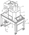
FIG. 1 is a schematic view of the overall structure of the present invention;
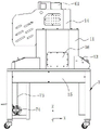
FIG. 2 is a front view of FIG. 1;
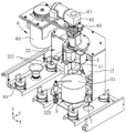
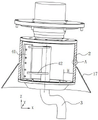
FIG. 3 is a schematic view of the internal structure of the present invention;
FIG. 4 is a further detailed structural schematic of the present invention;
FIG. 5 is a schematic view of the connection of the doctor assembly to the first delivery tube;
FIG. 6 is a view showing the positional relationship between the doctor assembly and the rotary drum;
FIG. 7 is an enlarged view of a portion of FIG. 6;
FIG. 8 is a schematic illustration of the retarder and clutch connection;
the reference numbers are that a frame 1, a first shell 11, a distribution box 12, a control panel 13, a second shell 14, a third shell 15, an access panel 16, a coaming 17, a rotary drum 2, a cake filtering layer 21, an oil storage cavity 22, an oil guide pipe 221, a first conveying pipe 3, a discharge hole 31, a rotary seat 32, a cleaning assembly 4, a scraper assembly 41, an arc-shaped support 42, a waste hopper 5, a cover 51, a first driving assembly 52, a corner cylinder 521, a second driving assembly 6, a speed reducer 61, a clutch 62, a second driving piece 63, a second telescopic piece 64, a third driving assembly 7, a third telescopic piece 71, a hinged rod 72, a second conveying pipe 73, a conveying pump 74, a mounting plate 8 and a shock absorber 81.
Detailed Description
The technical solutions in the embodiments of the present invention will be clearly and completely described below with reference to the drawings in the embodiments of the present invention, and it is obvious that the described embodiments are only a part of the embodiments of the present invention, and not all of the embodiments. All other embodiments, which can be obtained by a person skilled in the art without making any creative effort based on the embodiments in the present invention, belong to the protection scope of the present invention.
In the description of the present invention, it is to be understood that the terms "center", "longitudinal", "lateral", "length", "width", "thickness", "upper", "lower", "front", "rear", "left", "right", "vertical", "horizontal", "top", "bottom", "inner", "outer", "clockwise", "counterclockwise", and the like, indicate orientations or positional relationships based on those shown in the drawings, merely for convenience of description and simplicity of description, and do not indicate or imply that the device or element so referred to must have a particular orientation, be constructed in a particular orientation, and be operated, and thus, are not to be construed as limiting the present invention. Furthermore, the terms "first", "second" and "first" are used for descriptive purposes only and are not to be construed as indicating or implying relative importance or to implicitly indicate the number of technical features indicated. Thus, a feature defined as "first" or "second" may explicitly or implicitly include one or more of that feature. In the description of the present invention, "a plurality" means two or more unless specifically defined otherwise.
Example one
As shown in fig. 1 to 4, an automatic discharge centrifugal solid-liquid separator includes:
a frame 1;
the rotary drum 2 rotates centrifugally, the bottom of the rotary drum 2 is hollowed out, and the rotary drum 2 is rotatably connected with the rack 1;
the upper end of the first conveying pipe 3 for conveying the mixture extends into the rotary drum 2, and the upper end of the first conveying pipe 3 is provided with a plurality of discharging holes 31;
the cleaning assembly 4 is used for cleaning the inner wall of the rotary drum 2, and the cleaning assembly 4 is arranged on the first conveying pipe 3;
the first shell 11 is connected with the bottom of the rotary drum 2 and is sleeved outside the rotary drum 2, the first shell 11 and the outer surface of the rotary drum 2 are enclosed to form an oil storage cavity 22, and the first shell 11 is connected with the rack 1.
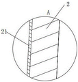
Further, the inner wall of rotary drum 2 encloses to close and is provided with worry cake layer 21, the bottom of rotary drum 2 is less than the diameter of rotary drum 2 upper end for fretwork form and rotary drum 2's lower extreme, first conveyer pipe 3 spouts to on centrifugal pivoted rotary drum 2, most mixtures are attached to the cake layer 21 of considering of rotary drum 2 inner wall department under rotary drum 2's centrifugal force, realize the centrifugation of fluid in the mixture, the fluid of centrifugation play flows into in the oil storage chamber 22 after worrying cake layer 21 and rotary drum 2 through worrying, clearance subassembly 4 clears up rotary drum 2 inner wall behind mixture centrifugal separation, with guarantee rotary drum 2 with comparatively invariable efficiency to mixture centrifugal separation, avoid rotary drum 2 inner wall department to block up and be difficult to carry out centrifugal separation work next time.
The cleaning assembly 4 comprises a scraper assembly 41 connected to the outer wall of the first conveying pipe 3.
The first conveying pipe 3 is connected with the scraper component 41 through an arc-shaped support 42.
Further, scrape the material through scraper subassembly 41 to the inside of rotary drum 2, strike off the solid waste who separates out in the mixture and make it fall from rotary drum 2 bottom, because scraper subassembly 41 is connected on the outer wall of first conveyer pipe 3 through arc support 42, make scraper subassembly 41 keep away from the state that most structures of a side of rotary drum 2 inner wall are in unsettled and not connected with other part, thereby make scraper subassembly 41 when striking off solid waste, the solid waste that scraper subassembly 41 surface pile up will follow scraper subassembly 41 and keep away from one side that rotary drum 2 inner wall falls down naturally, and then make things convenient for the blanking after scraper subassembly 41 strikes off solid waste.
The doctor assembly 41 is inclined towards the inner surface of the drum 2.
Further, the scraper assembly 41 is perpendicular to the rotary drum 2 and most damages the cutting edge of the scraper assembly 41 when scraping the solid waste, and the scraper assembly 41 is set to be inclined towards the inner surface of the rotary drum 2, so that the scraper assembly 41 scrapes the solid waste on the inner surface of the rotary drum 2 in a 'shoveling' manner, the resistance of the scraper assembly 41 when scraping the solid waste is reduced, the wear degree of the scraper assembly 41 when scraping the solid waste is reduced, the service life of the scraper assembly 41 is prolonged, and the provided power energy is saved.
The width of the scraper component 41 along the radius direction of the rotary drum 2 is not less than the distance H from the bottom hollow position of the rotary drum 2 to the maximum inner diameter surface of the rotary drum 2.
The solid waste accumulated on the surface of the scraper component 41 naturally falls from one side of the scraper component 41 far away from the inner wall of the rotary drum 2, so that the scraper component 41 can conveniently fall from the hollow part at the bottom of the rotary drum 2 right after scraping the solid waste, and the problem that the solid waste is collided with the inner side wall of the rotary drum 2 when falling and is adsorbed on the rotary drum 2 again under the action of centrifugal force when the scraper component 41 scrapes the solid waste on the rotary drum 2 is avoided.
Example two
As shown in fig. 3-8, where the same or corresponding parts as in the first embodiment have been given the same reference numerals as in the first embodiment, only the differences from the first embodiment will be described below for the sake of convenience. The second embodiment is different from the first embodiment in that: the bottom of the rotary drum 2 is provided with a waste hopper 5 with a cover 51, and a first driving assembly 52 for driving the cover 51 to close or open the waste hopper 5 is arranged beside the waste hopper 5.
The first driving assembly 52 drives the cover 51 to close or open by using rotary power.
The first drive assembly 52 includes a corner cylinder 521.
Further, before scraping the solid waste with scraper assembly 41, first driving assembly 52 drives lid 51 to rotate or rotate after rising to open waste bin 5, so as to realize the collection of the solid waste, and first driving assembly 52 includes a corner cylinder 521, and drives lid 51 at the upper end of waste bin 5 to rise through corner cylinder 521 and then to rotate a certain angle around corner cylinder 521 and then to keep away from waste bin 5, so as to realize the opening of lid 51 at the upper end of waste bin 5.
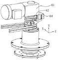
A second drive assembly 6 for driving the drum 2 in centrifugal rotation is also included.
The second driving assembly 6 comprises a speed reducer 61, and the speed reducer 61 is arranged on the frame 1;
the clutch 62 is in transmission connection with the speed reducer 61, and the clutch 62 is positioned at the upper part of the rotary drum 2;
the second driving piece 63, the second driving piece 63 is in transmission connection with the rotary drum 2 through a belt;
a second telescopic member 64, wherein the second telescopic member 64 used for driving the clutch 62 to be connected with or disconnected from the upper part of the rotary drum 2 is arranged on the frame 1;
further, the second telescopic member 64 is a telescopic cylinder or a telescopic hydraulic cylinder or an electric telescopic rod, and the second driving member 63 includes, but is not limited to, a servo motor; a speed reducing motor in transmission connection with the speed reducer 61 is arranged beside the speed reducer 61; the second driving part 63 drives the rotary drum 2 to centrifugally rotate through a belt, when scraping is needed, the second driving part 63 stops driving, the second telescopic part 64 drives the clutch 62 to be in transmission connection with the upper part of the rotary drum 2 through stretching, so that the speed reducing motor drives the rotary drum 2 to rotate through the speed reducer 61 and the clutch 62, and the speed of the rotary drum 2 is adjusted during scraping; the lower part of frame 1 is provided with block terminal 12, and the middle part of frame 1 is provided with control panel 13, and control panel 13's side is provided with the display screen, and second extensible member 64, second driving piece 63, block terminal 12, control panel 13 and display screen electricity are connected, through opening and close of control panel 13 control second driving piece 63 and second extensible member 64 to and the speed reduction gear of control reduction gear 61, thereby realize the centrifugal pivoted speed regulation of rotary drum 2.
The lower end of the first conveying pipe 3 is connected with a third driving component 7 which is used for driving the first conveying pipe 3 to rotate so as to enable the cleaning component 4 to be close to or attached to the inner wall of the rotary drum 2.
Further, the material used for the first conveying pipe 3 is a hard material, such as metal, and the third driving assembly 7 drives the first conveying pipe 3 to rotate, so that the scraper assembly 41 on the first conveying pipe 3 is close to and contacts the rotary drum 2, and under the rotation of the rotary drum 2, the solid waste attached to the rotary drum 2 is scraped.
The third drive assembly 7 comprises:
a third telescopic member 71, wherein the third telescopic member 71 is fixed on the frame 1;
and one end of the hinge rod 72 is hinged with the end part of the third telescopic part 71, and the other end of the hinge rod 72 is fixedly connected with the first conveying pipe 3.
Further, a second delivery pipe 73 is rotatably connected to the lower end of the first delivery pipe 3, and a delivery pump 74 is disposed on the second delivery pipe 73.
Furthermore, the third telescopic member 71 is a telescopic cylinder or a telescopic hydraulic cylinder or an electric telescopic rod, the hinge rod 72 can be made of elastic rubber materials, and the third telescopic member 71 pushes the hinge rod 72 to enable the hinge rod 72 to drive the first conveying pipe 3 to rotate around the upper end of the second conveying pipe 73, so that the scraper component 41 on the first conveying pipe 3 is close to the rotary drum 2, and the cutting edge of the scraper component is close to or attached to the rotary drum 2, so that the solid waste on the rotary drum 2 is scraped, and the automation level is further improved; the transfer pump 74 is, but is not limited to, a 4.5KW pump station.
The rack 1 comprises a mounting plate 8 arranged in the middle of the rack 1, and the rack 1 is also provided with a shock absorber 81 abutted against the mounting plate 8; the lower end of the first delivery pipe 3 is provided with a rotary seat 32 connected to the mounting plate 8.
Further, the first delivery pipe 3 takes a rotary seat 32 on the mounting plate 8 as a rotary center, and the first delivery pipe 3 is rotatably connected with the rotary seat 32; shock absorber 81 is damping spring shock absorber, shock absorber 81 is installed in frame 1 and is contradicted on mounting panel 8, on the one hand, shock absorber 81 can be to the holistic shock attenuation that carries out of automatic discharge centrifugal solid-liquid separation machine, on the other hand, carry out the shock attenuation to mounting panel 8 through shock absorber 81, can reduce the vibration volume of revolving bed 32 and first conveyer pipe 3, and scraper subassembly 41 is installed on the upper portion of first conveyer pipe 3, thereby can reduce scraper subassembly 41's vibration volume, therefore, can reduce scraper subassembly 41's blade and rotary drum 2 inner wall contact collision through setting up shock absorber 81, thereby improve scraper subassembly 41's life.
The upper end of first casing 11 is provided with second casing 14, the lower extreme of first casing 11 is provided with third casing 15, and all is provided with access panel 16 on first casing 11, second casing 14 and the third casing 15.
Further, the first casing 11, the second casing 14 and the third casing 15 are arranged to facilitate the integral installation and disassembly of the automatic discharging centrifugal solid-liquid separator, and the access panel 16 is arranged to facilitate the easy access of the automatic discharging centrifugal solid-liquid separator.
The first housing 11 is connected to the bottom of the drum 2 via an inverted funnel-shaped enclosure 17. The baffle 17 is arranged to facilitate the diversion of the separated oil.
Working procedure
The working principle is as follows: the mixture is conveyed into the first conveying pipe 3 through the conveying pump 74 and the second conveying pipe 73, is sprayed out through the discharging hole 31 on the side surface of the upper part of the first conveying pipe 3 and is sprayed onto the inner wall of the rotary drum 2, the rotary drum 2 is driven by the first driving assembly 52 to rotate centrifugally, the mixture is sprayed onto the inner wall of the rotary drum 2 and then moves centrifugally along with the rotary drum 2, oil in the mixture is separated from the rotary drum 2 under the action of centrifugal force and flies out of the rotary drum 2 to enter the oil storage chamber 22, the oil storage chamber 22 is connected with the outside through an oil guide pipe 221, and the separated oil is discharged through the oil guide pipe 221; the solid waste is left on the inner wall of the rotary drum 2 to continue to do centrifugal motion, when the batch of mixture is centrifuged for a period of time and then the separation of the oil liquid and the solid waste is finished, the second driving member 63 stops driving, the second expansion member 64 drives the clutch 62, the speed reducer 61 is in transmission connection with the rotary drum 2, the drum 2 is driven by a speed reducing motor to rotate in a speed reducing way, then the cover 51 is driven by the first driving assembly 52 to open the upper part of the waste hopper 5, then the third telescopic part 71 pushes the hinge rod 72 to rotate for a certain angle so as to rotate the first conveying pipe 3, the first conveying pipe 3 rotates and drives the scraper assembly 41 to rotate for a certain angle, so as to realize that the scraper component 41 on the first conveying pipe 3 is close to and the cutting edge is close to the inner wall of the rotary drum 2 to scrape off the solid waste on the rotary drum 2, the solid waste drops from the scraper component 41 and enters the waste hopper 5 to be collected, and the next separation work is performed after the solid-liquid separation of a round of mixture is completed.
The above description is intended to be illustrative of the preferred embodiment of the present invention and should not be taken as limiting the utility model, but rather, the intention is to cover all modifications, equivalents, and alternatives falling within the spirit and scope of the utility model.
Claims (10)
1. An automatic centrifugal solid-liquid separation machine of unloading characterized by, includes:
a frame (1);
the rotary drum (2) rotates centrifugally and is hollow at the bottom, and the rotary drum (2) is rotatably connected with the rack (1);
the upper end of the first conveying pipe (3) for conveying the mixture extends into the rotary drum (2), and the upper end of the first conveying pipe (3) is provided with a plurality of discharging holes (31);
the cleaning assembly (4) is used for cleaning the inner wall of the rotary drum (2), and the cleaning assembly (4) is arranged on the first conveying pipe (3);
the first shell (11) is connected with the bottom of the rotary drum (2) and surrounds the first shell (11) of the oil storage cavity (22) with the outer surface of the rotary drum (2) to form a sleeve, and the first shell (11) is connected with the rack (1).
2. An automatic discharge centrifugal solid-liquid separator according to claim 1, characterized in that said cleaning assembly (4) comprises a scraper assembly (41) connected to the outer wall of said first conveying pipe (3).
3. An automatic discharge centrifugal solid-liquid separator according to claim 2, characterized in that said scraper assembly (41) is inclined towards the inner surface of the bowl (2).
4. The centrifugal solid-liquid separator of claim 2, wherein the width of the scraper assembly (41) along the radius direction of the rotary drum (2) is not less than the distance H from the bottom hollow position of the rotary drum (2) to the maximum inner diameter surface of the rotary drum (2).
5. The centrifugal solid-liquid separator of claim 1, wherein the bottom of the drum (2) is provided with a waste hopper (5) with a cover (51), and a first driving assembly (52) for driving the cover (51) to close or open the waste hopper (5) is arranged beside the waste hopper (5).
6. The centrifugal solid-liquid separator according to claim 5, wherein the first drive assembly (52) uses rotational power to drive the cover (51) to close or open.
7. An automatic discharge centrifugal solid-liquid separator according to claim 6, characterized in that said first drive assembly (52) comprises an angle cylinder (521).
8. The centrifugal solid-liquid separator of claim 2, wherein the lower end of the first conveying pipe (3) is connected with a third driving assembly (7) for driving the first conveying pipe (3) to rotate so as to enable the cleaning assembly (4) to be close to or attached to the inner wall of the rotary drum (2).
9. An automatic discharge centrifugal solid-liquid separator according to claim 1, wherein: the rack (1) comprises a mounting plate (8) arranged in the middle of the rack (1), and a shock absorber (81) abutting against the mounting plate (8) is further arranged on the rack (1); the lower end of the first conveying pipe (3) is provided with a rotary seat (32) connected to the mounting plate (8).
10. An automatic discharge centrifugal solid-liquid separator according to claim 1, wherein: the first shell (11) is connected with the bottom of the rotary drum (2) through an inverted funnel-shaped enclosing plate (17).
Applications Claiming Priority (2)
| Application Number | Priority Date | Filing Date | Title |
|---|---|---|---|
| CN202123182636 | 2021-12-17 | ||
| CN2021231826367 | 2021-12-17 |
Publications (1)
| Publication Number | Publication Date |
|---|---|
| CN217017012U true CN217017012U (en) | 2022-07-22 |
Family
ID=82444437
Family Applications (1)
| Application Number | Title | Priority Date | Filing Date |
|---|---|---|---|
| CN202220029536.6U Active CN217017012U (en) | 2021-12-17 | 2022-01-07 | Automatic centrifugal solid-liquid separation machine of unloading |
Country Status (1)
| Country | Link |
|---|---|
| CN (1) | CN217017012U (en) |
Cited By (1)
| Publication number | Priority date | Publication date | Assignee | Title |
|---|---|---|---|---|
| CN116550479A (en) * | 2023-07-03 | 2023-08-08 | 河南中正石油起重机械有限公司 | Drilling fluid rapid filtration centrifuge |
-
2022
- 2022-01-07 CN CN202220029536.6U patent/CN217017012U/en active Active
Cited By (2)
| Publication number | Priority date | Publication date | Assignee | Title |
|---|---|---|---|---|
| CN116550479A (en) * | 2023-07-03 | 2023-08-08 | 河南中正石油起重机械有限公司 | Drilling fluid rapid filtration centrifuge |
| CN116550479B (en) * | 2023-07-03 | 2023-09-19 | 河南中正石油起重机械有限公司 | Drilling fluid rapid filtration centrifuge |
Similar Documents
| Publication | Publication Date | Title |
|---|---|---|
| CN211412153U (en) | New forms of energy refuse treatment device | |
| CN110948695B (en) | Cement mixer capable of automatically disassembling materials | |
| CN217017012U (en) | Automatic centrifugal solid-liquid separation machine of unloading | |
| KR20160008731A (en) | Dust collector | |
| CN105880042A (en) | Spiral scraping type vertical centrifugal machine | |
| CN115253473A (en) | Recovery unit is handled to waste mineral oil | |
| CN106041632A (en) | Device and method for recovering cooling liquid for machining | |
| CN104888979A (en) | Gravity discharge screen centrifuge | |
| CN219483012U (en) | High-efficient centrifugal device | |
| CN112122296A (en) | Mixed dust removal equipment based on powder coating for plastic processing | |
| CN220215305U (en) | Discharging mechanism of horizontal centrifuge | |
| CN212041007U (en) | Horizontal scraper discharge centrifuge capable of discharging materials rapidly | |
| CN219784877U (en) | Centrifugal concentrating machine | |
| CN220012179U (en) | Environment-friendly engineering industrial wastewater dephosphorization treatment mechanism | |
| CN116803535B (en) | Dustproof mechanism of cement processing equipment | |
| CN220111339U (en) | Automatic sediment centrifuge of arranging of scraper unloading | |
| CN220578271U (en) | Material screening structure suitable for food processing | |
| CN219965220U (en) | Centrifuge with noise reduction function | |
| CN218282152U (en) | Horizontal scraper discharge centrifuge | |
| CN218742560U (en) | Flat plate type centrifuge | |
| CN214811516U (en) | Grinding machine is used in production of concise coconut oil | |
| CN214682317U (en) | Centrifuge for automatically extracting high-purity copper sulfate | |
| CN215465260U (en) | Horizontal centrifuge is from clearance aircraft bonnet with adjust structure | |
| CN218501453U (en) | Grease processing raw materials edulcoration device | |
| CN218260519U (en) | Internal rotation scraper type coal bucket blockage removing machine |
Legal Events
| Date | Code | Title | Description |
|---|---|---|---|
| GR01 | Patent grant | ||
| GR01 | Patent grant |