CN216966608U - Pre-welding machine convenient to adjust spot welding position - Google Patents
Pre-welding machine convenient to adjust spot welding position Download PDFInfo
- Publication number
- CN216966608U CN216966608U CN202220615165.XU CN202220615165U CN216966608U CN 216966608 U CN216966608 U CN 216966608U CN 202220615165 U CN202220615165 U CN 202220615165U CN 216966608 U CN216966608 U CN 216966608U
- Authority
- CN
- China
- Prior art keywords
- fixedly connected
- guide rail
- rotating rod
- spot welding
- worm
- Prior art date
- Legal status (The legal status is an assumption and is not a legal conclusion. Google has not performed a legal analysis and makes no representation as to the accuracy of the status listed.)
- Active
Links
Images


Landscapes
- Resistance Welding (AREA)
Abstract
The utility model relates to the technical field of prewelding, in particular to a prewelding machine convenient for adjusting spot welding positions, which comprises a workbench, wherein the top of the workbench is fixedly connected with an installation frame, the surface of the installation frame is fixedly connected with a first electric guide rail, the surface of the first electric guide rail is fixedly connected with a telescopic rod, the improved prewelding machine drives a worm to rotate by rotating a rotating rod, the worm drives a worm wheel to rotate, the worm wheel drives a material placing table to deflect, the prewelding machine can weld the side surface of a workpiece, the welding range of the prewelding machine can be effectively increased, the gear is driven to rotate by the rotating rod, a spring is compressed by force, a fixed rod is pushed by a sliding rod to abut against the gear, the rotating rod is fixed, when the fixed rod is loosened, the rotating rod can automatically reset due to the reaction force of the spring, and the problem that the material placing table needs to be manually reset when the next workpiece is welded is solved, the working time is effectively reduced, and the working efficiency is improved.
Description
Technical Field
The utility model relates to the technical field of prewelding, in particular to a prewelding machine convenient for adjusting spot welding positions.
Background
The pre-welding machine adopts the principle of double-sided double-point overcurrent welding, when the pre-welding machine works, two electrodes pressurize a workpiece to enable two layers of metal to form a certain contact resistance under the pressure of the two electrodes, when welding current flows from one electrode to the other electrode, instant thermal welding is formed at two contact resistance points, and the welding current instantly flows from the other electrode to the electrode along the two workpieces to form a loop, so that the internal structure of the workpiece to be welded cannot be damaged.
The welding is carried out again after current pre-welder places the work piece on putting the thing platform. The inventor finds that the prior art has the following problems: the existing pre-welding machine can only pre-weld one side and cannot pre-weld the rest sides.
SUMMERY OF THE UTILITY MODEL
The present invention is directed to a pre-welding machine which facilitates adjustment of spot welding positions to solve the problems set forth in the background art. In order to achieve the purpose, the utility model provides the following technical scheme: a pre-welding machine convenient for adjusting spot welding positions comprises a workbench, wherein the top of the workbench is fixedly connected with an installation frame, the surface of the installation frame is fixedly connected with a first electric guide rail, the surface of the first electric guide rail is fixedly connected with a telescopic rod, the bottom of the telescopic rod is fixedly connected with a welding pen, and the top of the workbench is fixedly connected with a second electric guide rail;
the top of the second electric guide rail is fixedly connected with an installation table, the interior of the installation table is rotatably connected with a rotating rod, the surface of the rotating rod is fixedly sleeved with a worm, the top of the installation table is fixedly connected with a connecting frame, the interior of the connecting frame is rotatably connected with a worm wheel, the worm wheel is meshed with the worm, the top of the worm wheel is fixedly connected with a connecting sleeve, and the top of the connecting sleeve is rotatably connected with a storage table;
the guide way has been seted up to the inside of mount table, the inside sliding connection of guide way has the dead lever, the equal fixedly connected with slide bar in both ends around the dead lever, the slide bar activity runs through in the mount table, the fixed surperficial cover of dwang has connect the gear, gear and dead lever activity butt, the surface activity of dwang has cup jointed the spring, the both ends of spring respectively with mount table and gear fixed connection.
Preferably, the surface of the object placing table is provided with anti-skid grains.
Further preferably, a hand lever is fixedly connected to the right end of the rotating lever.
Further preferably, the left end of the rotating rod is rotatably connected to the mounting table through a bearing.
Further preferably, a power box is installed at the top of the mounting rack, and the first electric guide rail and the second electric guide rail are electrically connected with the power box.
Further preferably, a protective gas cylinder is placed at the top of the workbench, a protective gas pipe is installed on the welding pen, and the protective gas pipe is connected with the protective gas cylinder.
Compared with the prior art, the utility model has the beneficial effects that:
according to the utility model, the worm is driven to rotate by rotating the rotating rod, and the worm drives the worm wheel to rotate, so that the worm wheel drives the object placing table to deflect, the pre-welding machine can weld the side surface of the workpiece, the welding range of the pre-welding machine can be effectively increased, and the working efficiency is improved.
According to the utility model, the gear is driven to rotate through the rotating rod, the spring is compressed under stress, the fixed rod is pushed to abut against the gear through the sliding rod, the rotating rod is fixed, and when the fixed rod is loosened, the rotating rod can automatically reset due to the counterforce of the spring, so that the problem that the object placing table needs to be manually reset when the next workpiece is welded is solved, the working time is effectively reduced, and the working efficiency is improved.
Drawings
FIG. 1 is a schematic front view of the present invention;
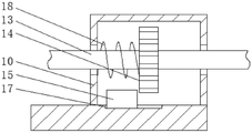
FIG. 2 is an enlarged schematic view of FIG. 1 at A according to the present invention;
FIG. 3 is a schematic view of a partially enlarged front cross-sectional structure of the mounting table of the present invention;
FIG. 4 is a schematic view of a partially enlarged side-sectional structure of the mounting stage of the present invention.
In the figure: 1. a first motorized rail; 2. a mounting frame; 3. a work table; 4. a telescopic rod; 5. a welding pen; 6. a placing table; 7. connecting sleeves; 8. a worm gear; 9. a connecting frame; 10. an installation table; 11. a second motorized rail; 12. a worm; 13. rotating the rod; 14. a gear; 15. fixing the rod; 16. a slide bar; 17. a guide groove; 18. a spring.
Detailed Description
The technical solutions in the embodiments of the present invention will be clearly and completely described below with reference to the drawings in the embodiments of the present invention, and it is obvious that the described embodiments are only a part of the embodiments of the present invention, and not all of the embodiments. All other embodiments, which can be obtained by a person skilled in the art without any inventive step based on the embodiments of the present invention, are within the scope of the present invention.
Referring to fig. 1 to 4, the present invention provides a technical solution: a pre-welding machine convenient for adjusting spot welding positions comprises a workbench 3, wherein the top of the workbench 3 is fixedly connected with an installation frame 2, the surface of the installation frame 2 is fixedly connected with a first electric guide rail 1, the surface of the first electric guide rail 1 is fixedly connected with a telescopic rod 4, the bottom of the telescopic rod 4 is fixedly connected with a welding pen 5, and the top of the workbench 3 is fixedly connected with a second electric guide rail 11;
the top of the second electric guide rail 11 is fixedly connected with an installation table 10, the inside of the installation table 10 is rotatably connected with a rotating rod 13, the surface of the rotating rod 13 is fixedly sleeved with a worm 12, the top of the installation table 10 is fixedly connected with a connecting frame 9, the inside of the connecting frame 9 is rotatably connected with a worm wheel 8, the worm wheel 8 is meshed with the worm 12, the top of the worm wheel 8 is fixedly connected with a connecting sleeve 7, and the top of the connecting sleeve 7 is rotatably connected with an object placing table 6;
In this embodiment, as shown in fig. 1 and fig. 2, the surface of the object placing table 6 is provided with anti-slip patterns, so that the friction between the object placing table 6 and the welding plate can be increased through the anti-slip patterns, the welding plate can be more stably placed on the object placing table 6, and the pre-welding precision is improved.
In this embodiment, as shown in fig. 1 and fig. 2, a hand lever is fixedly connected to the right end of the rotating lever 13, so that a user can have an origin of force through the hand lever, and the rotating lever 13 can be rotated through the hand lever more conveniently.
In this embodiment, as shown in fig. 1 and 2, the left end of the rotating rod 13 is rotatably connected to the mounting table 10 through a bearing, and the rotating rod 13 is fixed to the mounting table 10 through the bearing, so that the rotating rod 13 can rotate more stably.
In this embodiment, as shown in fig. 1, a power box is installed on the top of the mounting rack 2, the first electric rail 1 and the second electric rail 11 are electrically connected to the power box, and power is simultaneously supplied to the first electric rail 1 and the second electric rail 11 through the power box.
In this embodiment, as shown in fig. 1, a protection gas cylinder is placed at the top of the workbench 3, and a protection gas pipe is installed on the welding pen 5 and connected with the protection gas cylinder, so that the surface of the welding spot is not oxidized by protecting the gas of the protection gas cylinder, thereby improving the production efficiency.
The use method and the advantages of the utility model are as follows: this kind of prewelding machine convenient to adjust spot welding position is when the rolling, and the working process as follows:
as shown in fig. 1, fig. 2, fig. 3 and fig. 4, firstly, a workpiece is placed on the object placing table 6, the positions of the first electric guide rail 1 and the second electric guide rail 11 are adjusted according to the welding position required, after the adjustment is completed, when the side surface is welded according to the requirement, the rotating rod 13 is rotated, the rotating rod 13 drives the worm 12 to rotate, the worm 12 drives the worm wheel 8 to rotate, the worm wheel 8 drives the object placing table 6 to deflect through the connecting sleeve 7, the workpiece is driven to deflect by the object placing table 6, so that the pre-welding machine can weld the side surface of the workpiece, the welding range of the pre-welding machine can be effectively increased, the working efficiency is improved, the gear 14 is driven to rotate through the rotating rod 13, the spring 18 is compressed under the force, the fixing rod 15 is pushed to move along the track of the guide groove 17 through the sliding rod 16, when the fixing rod 15 abuts against the gear 14, the rotating rod 13 can be fixed, and the fixing rod 15 is moved away, dwang 13 can have solved the problem that needs manual when welding next work piece will put thing platform 6 and reset because spring 18's reaction force automatic re-setting, and the effectual time that reduces work improves work efficiency.
The foregoing shows and describes the general principles, essential features, and advantages of the utility model. It will be understood by those skilled in the art that the present invention is not limited to the embodiments described above, and the preferred embodiments of the present invention are described in the above embodiments and the description, and are not intended to limit the present invention. The scope of the utility model is defined by the appended claims and equivalents thereof.
Claims (6)
1. The utility model provides a prewelding machine convenient to adjust spot welding position, includes workstation (3), its characterized in that: the top of the workbench (3) is fixedly connected with an installation frame (2), the surface of the installation frame (2) is fixedly connected with a first electric guide rail (1), the surface of the first electric guide rail (1) is fixedly connected with a telescopic rod (4), the bottom of the telescopic rod (4) is fixedly connected with a welding pen (5), and the top of the workbench (3) is fixedly connected with a second electric guide rail (11);
the top of the second electric guide rail (11) is fixedly connected with an installation table (10), the interior of the installation table (10) is rotatably connected with a rotating rod (13), a worm (12) is fixedly sleeved on the surface of the rotating rod (13), the top of the installation table (10) is fixedly connected with a connecting frame (9), the interior of the connecting frame (9) is rotatably connected with a worm wheel (8), the worm wheel (8) is meshed with the worm (12), the top of the worm wheel (8) is fixedly connected with a connecting sleeve (7), and the top of the connecting sleeve (7) is rotatably connected with an object placing table (6);
guide way (17) have been seted up to the inside of mount table (10), the inside sliding connection of guide way (17) has dead lever (15), the equal fixedly connected with slide bar (16) in both ends around dead lever (15), slide bar (16) activity runs through in mount table (10), gear (14) have been cup jointed to the fixed surface of dwang (13), gear (14) and dead lever (15) activity butt, spring (18) have been cup jointed to the surface activity of dwang (13), the both ends of spring (18) respectively with mount table (10) and gear (14) fixed connection.
2. A prewelder for facilitating the adjustment of spot welding positions, according to claim 1, characterized by: the surface of the object placing table (6) is provided with anti-skid grains.
3. A prewelder for facilitating the adjustment of spot welding positions, according to claim 1, characterized by: the right end of the rotating rod (13) is fixedly connected with a hand lever.
4. A prewelder for facilitating the adjustment of spot welding positions, according to claim 1, characterized by: the left end of the rotating rod (13) is rotatably connected to the mounting table (10) through a bearing.
5. A prewelder for facilitating the adjustment of spot welding positions, according to claim 1, characterized by: the power box is installed at the top of mounting bracket (2), first electronic guide rail (1) and second electronic guide rail (11) are connected with the power box electricity.
6. A prewelder for facilitating the adjustment of spot welding positions, according to claim 1, characterized by: a protective gas cylinder is placed at the top of the workbench (3), a protective gas pipe is installed on the welding pen (5), and the protective gas pipe is connected with the protective gas cylinder.
Priority Applications (1)
| Application Number | Priority Date | Filing Date | Title |
|---|---|---|---|
| CN202220615165.XU CN216966608U (en) | 2022-03-18 | 2022-03-18 | Pre-welding machine convenient to adjust spot welding position |
Applications Claiming Priority (1)
| Application Number | Priority Date | Filing Date | Title |
|---|---|---|---|
| CN202220615165.XU CN216966608U (en) | 2022-03-18 | 2022-03-18 | Pre-welding machine convenient to adjust spot welding position |
Publications (1)
| Publication Number | Publication Date |
|---|---|
| CN216966608U true CN216966608U (en) | 2022-07-15 |
Family
ID=82359071
Family Applications (1)
| Application Number | Title | Priority Date | Filing Date |
|---|---|---|---|
| CN202220615165.XU Active CN216966608U (en) | 2022-03-18 | 2022-03-18 | Pre-welding machine convenient to adjust spot welding position |
Country Status (1)
| Country | Link |
|---|---|
| CN (1) | CN216966608U (en) |
-
2022
- 2022-03-18 CN CN202220615165.XU patent/CN216966608U/en active Active
Similar Documents
| Publication | Publication Date | Title |
|---|---|---|
| CN102513755B (en) | Automatic tracking seam welding/cutting manipulator | |
| CN218311745U (en) | Dual-purpose laser cutting machine anchor clamps of board pipe | |
| CN216966608U (en) | Pre-welding machine convenient to adjust spot welding position | |
| CN211052954U (en) | Robot welding device | |
| CN217859541U (en) | Photovoltaic support welding device for building photovoltaic power station | |
| CN217859639U (en) | Vacuum switch tube positioning and assembling die | |
| CN214236893U (en) | Novel precise combination mechanism of welding equipment | |
| CN216325730U (en) | Equipment support welding equipment with positioning mechanism | |
| CN212217399U (en) | Argon arc welding equipment | |
| CN210001889U (en) | clamping device for heat treatment of metal materials | |
| CN218135646U (en) | Spot welding machine with automatic feeding mechanism | |
| CN111673326A (en) | Intelligent welding equipment for automobile frame | |
| CN201997836U (en) | Automatic welding machine for turbochargers | |
| CN217799531U (en) | Multipoint spot welding machine for producing automobile silencer | |
| CN215698761U (en) | Automatic grounding assembly for TIG welding chuck | |
| CN111375966A (en) | Outer end cover pressure equipment frock of car aftertreatment | |
| CN218050806U (en) | Fixed point adjusting mechanism of spot welding machine | |
| CN213224830U (en) | Welding device with fixing mechanism for automobile machining | |
| CN219425902U (en) | Flux-cored wire surfacing equipment | |
| CN216126758U (en) | Spot welding device is used in new energy automobile's battery production | |
| CN221087585U (en) | Automatic spot welding special plane that snatchs of stationary blade | |
| CN217618339U (en) | Resistance welding device for T-shaped welding | |
| CN210649214U (en) | Welding equipment for spare tire bracket | |
| CN220312060U (en) | Resistance spot welding device capable of preventing welding flux from splashing | |
| CN217551578U (en) | Subway vehicle door stand equipment |
Legal Events
| Date | Code | Title | Description |
|---|---|---|---|
| GR01 | Patent grant | ||
| GR01 | Patent grant |