CN216946430U - Combined reclaimed water advanced treatment system of carbon fiber ecological grass and constructed wetland - Google Patents
Combined reclaimed water advanced treatment system of carbon fiber ecological grass and constructed wetland Download PDFInfo
- Publication number
- CN216946430U CN216946430U CN202220339666.XU CN202220339666U CN216946430U CN 216946430 U CN216946430 U CN 216946430U CN 202220339666 U CN202220339666 U CN 202220339666U CN 216946430 U CN216946430 U CN 216946430U
- Authority
- CN
- China
- Prior art keywords
- water
- channel
- wetland
- water collecting
- subsurface flow
- Prior art date
- Legal status (The legal status is an assumption and is not a legal conclusion. Google has not performed a legal analysis and makes no representation as to the accuracy of the status listed.)
- Active
Links
Images

Classifications
-
- Y—GENERAL TAGGING OF NEW TECHNOLOGICAL DEVELOPMENTS; GENERAL TAGGING OF CROSS-SECTIONAL TECHNOLOGIES SPANNING OVER SEVERAL SECTIONS OF THE IPC; TECHNICAL SUBJECTS COVERED BY FORMER USPC CROSS-REFERENCE ART COLLECTIONS [XRACs] AND DIGESTS
- Y02—TECHNOLOGIES OR APPLICATIONS FOR MITIGATION OR ADAPTATION AGAINST CLIMATE CHANGE
- Y02W—CLIMATE CHANGE MITIGATION TECHNOLOGIES RELATED TO WASTEWATER TREATMENT OR WASTE MANAGEMENT
- Y02W10/00—Technologies for wastewater treatment
- Y02W10/10—Biological treatment of water, waste water, or sewage
Landscapes
- Purification Treatments By Anaerobic Or Anaerobic And Aerobic Bacteria Or Animals (AREA)
Abstract
The utility model discloses a reclaimed water advanced treatment system combining carbon fiber ecological grass and an artificial wetland, which is mainly a combined device of the carbon fiber ecological grass and the artificial wetland; the tail water of a sewage treatment plant is connected to a water collecting well, carbon fiber ecological grass and a lifting water pump are installed in the water collecting well, and are sequentially connected with a water delivery channel, a water distribution channel and a primary subsurface flow constructed wetland, a water collecting pipe and a first rotatable elbow are installed on the wall of the water outlet end of the water distribution channel, the primary subsurface flow constructed wetland consists of a water inlet area, a main body area and a water outlet area, a perforated water collecting pipe is installed at the bottom of the water outlet area and is connected to the water distribution channel through a second rotatable elbow, a main emptying pipe is installed at the bottom of the water distribution channel, the rear end of the primary subsurface flow constructed wetland is sequentially connected with a secondary subsurface flow constructed wetland and a water collecting channel, and the structures of the secondary subsurface flow constructed wetland and the water collecting channel are respectively the same as the primary subsurface flow wetland and the water distribution channel. Rotatable elbows are adopted in the places where the water level of the system can be adjusted, the problem of water level change of the wetland in winter and summer is solved, the labor force is reduced, and the operation cost is reduced.
Description
Technical Field
The utility model relates to a reclaimed water advanced treatment system combining carbon fiber ecological grass and an artificial wetland, belonging to the technical field of sewage treatment.
Background
The carbon fiber is a fibrous carbon material with good biocompatibility, is a novel material with large specific surface area, strong adsorption performance and good biocompatibility, and the carbon fiber ecological grass has huge specific surface area (higher than 1000 m) due to the special form thereof2/g), rich micropores and various functional groups, thereby having higher adsorptivity, effectively removing the color, smell, oil content, phenol and the like of the wastewater, simultaneously removing difficultly-degradable substances, and particularly having strong purification effect on ammonia nitrogen. The method is generally used for treating black and odorous water in riverways, and can effectively remove COD, ammonia nitrogen and total phosphorus.
The artificial wetland is a simulated natural wetland, a water tank or a groove is constructed artificially, an anti-seepage water-stop layer is laid on the bottom surface of the artificial wetland, soil or a filler layer with a certain depth is filled, vascular bundle plants such as reeds or aquatic plants with developed root systems are planted, sewage enters from one end of the wetland through a water distribution canal and is in full plant root area contact with the surface of a medium full of a biological membrane and dissolved oxygen in a plug flow manner to obtain purification. The method is a technology for treating sewage and sludge by mainly utilizing the physical, chemical and biological synergistic effects of soil, artificial media, plants and microorganisms. The action mechanism of the ecological artificial wetland comprises adsorption, detention, filtration, oxidation reduction, precipitation, microbial decomposition, transformation, plant shielding, residue accumulation, transpiration moisture and nutrient absorption and digestion and absorption of various animals, so that the harmless and recycling of the wastewater is realized, and the artificial wetland is an energy-saving, economical, simple and efficient ecological sewage treatment technology.
Chinese patent CN201410363521.3 (No. CN 104129857A) discloses an 'deep water purification artificial wetland system in alpine regions' which comprises a water distribution regulating reservoir, an undercurrent artificial wetland unit, an undercurrent unit water distribution system, an undercurrent water outlet well, a surface current artificial wetland and a system tail end water outlet well, wherein the regulating reservoir has an aeration function, the subsurface flow constructed wetland is a composite subsurface flow constructed wetland, sewage is subjected to primary purification treatment, a subsurface flow wetland unit is provided with an impermeable layer, a matrix packing layer and a planting soil layer, aquatic plants are planted on the surface of the subsurface flow wetland unit, the front end of the composite subsurface flow constructed wetland unit is provided with a pressure water distribution system, the rear end of the composite subsurface flow constructed wetland unit is provided with a unit water collection system, a high water outlet valve, a medium water outlet valve and a low water outlet valve are arranged in the system, water levels in the freezing period and the non-freezing period can be conveniently adjusted and used, meanwhile, a membrane inversion system is arranged in the system, and the surface flow wetland is used for secondary purification treatment of the sewage. Effluent can reach the III or IV standards of surface water of GB3838-2002, but the process structure does not indicate a sewage discharge direction and treatment method after membrane inversion, three water outlet valves of effluent are arranged too complicated, the management difficulty is higher, and meanwhile, a pretreatment system is not provided, so that the stability of the system is poor, and the stability of a reclaimed water treatment system can not be guaranteed to reach the standard.
Disclosure of Invention
Aiming at the defects in the prior art, the utility model provides a combined treatment system of carbon fiber ecological grass and artificial wetland, which can solve the problem of stable operation of the system and the problem of flexibly adjusting the height of the operating water level in the freezing period and the non-freezing period in the north of China.
In order to achieve the purpose, the utility model adopts the following technical scheme:
a reclaimed water advanced treatment system combining carbon fiber ecological grass and an artificial wetland is characterized in that the reclaimed water advanced treatment system is mainly a combined device of the carbon fiber ecological grass and the artificial wetland; wherein the tail water 1 of the sewage treatment plant is connected with a water collecting well 2, the water collecting well 2 is internally provided with a carbon fiber ecological grass 3 and a lifting water pump 4, the outlet of the lifting water pump 4 is connected with a water delivery channel 5, a water through hole 6 is arranged on the wall between the water delivery channel and a water distribution channel 7, the water distribution channel 7 is paved with an inspection port anticorrosive wood cover plate 8, the wall between the water distribution channel 7 and a primary subsurface flow constructed wetland 16 is provided with a water collecting pipe 9, a first rotatable elbow 10 and a waterproof sleeve 11, the primary subsurface flow constructed wetland 16 consists of a water inlet area 12, a main body area 17 and a water outlet area 18, the front end of the water inlet area 12 is paved with first phi 80-110 cobblestones 13 and is built with a water channel brick wall 14, the main body area 17 is internally provided with a filler, the lower part of the filler is a geomembrane and is fixed by a rivet 15, the water outlet area 18 is filled with second phi 80-110 cobblestones 19, the lower part is provided with a perforated water collecting pipe 20, the perforated water collecting pipe 20 is connected to a water collecting and distributing channel 23 through a second rotatable elbow 22 and a first water outlet pipe 21, a vent main pipe 28 is installed at the bottommost part in the water collecting and distributing channel 23, the water collecting and distributing channel 23 is connected with a second-stage subsurface flow artificial wetland 24, the internal structure of the second-stage subsurface flow artificial wetland 24 is the same as that of the first-stage subsurface flow wetland, a water collecting channel 25 is connected behind the second-stage subsurface flow artificial wetland, a second water outlet pipe 27 is installed in the water collecting channel 25 and connected with a third rotatable elbow 26, and the vent main pipe 28 is installed in the water collecting channel 25.
According to the utility model, carbon fiber ecological grass is added in the water collecting well, so that the stability of the system is greatly improved. The subsurface flow constructed wetland is characterized in that water is distributed from the front end to the rear end, all pipelines and pipe fittings needing water level adjustment adopt rotatable elbows, the use of the elbows realizes the free conversion of water level change between the freezing period and the non-freezing period in the north, and the elbows do not need to be easily rotated without any valve operation. An emptying main pipe 28 is arranged in the water collecting and distributing channel 23 and the water collecting channel 25, so that the function of self-cleaning of the filler is realized. Compared with a valve water distribution mode adopting a gate valve and a check valve, the construction mode that the front end of the front end water inlet area 12 is paved with first phi 80-110 cobblestones 13 and a water passing tile wall 14 is constructed saves a water metering instrument and is relatively uniform and stable in water distribution.
The filler comprises the following components: a. a rammed plain soil layer; b. a clay tamping layer; c. the soil-planting soil-covering layer comprises a geotechnical film layer, a 100mm coarse sand layer, an 80-120mm gravel layer, a f.30-80mm volcanic rock layer, a g.10-30mm gravel layer, a h.5-10mm gravel layer, a i coarse sand layer and a j planting soil layer.
Compared with the prior art, the reclaimed water advanced treatment system combining the carbon fiber ecological grass and the artificial wetland has the beneficial effects that:
1. the carbon fiber ecological grass is introduced into the artificial wetland pretreatment system, so that the stability problem of the artificial wetland treatment system is solved.
2. Rotatable elbows are adopted in the places where the water level of the system can be adjusted, so that the problem of water level conversion switching in the wetland in winter and summer is solved, and the labor force is reduced. The operation cost is reduced.
3. The reliability and stability of the system determine that the system is not only suitable for temperate zone plain areas, but also can be applied to alpine and anoxic areas.
4. The process system has uniform hydraulic water distribution and good advanced treatment effect, and the treated drainage can reach the III or IV standards of the surface water of GB 3838-2002.
Drawings
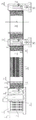
FIG. 1 is a schematic sectional view of a carbon fiber ecological grass and subsurface flow constructed wetland system of the utility model;
FIG. 2 is a schematic plane layout of the subsurface flow constructed wetland of the utility model;
in the figure:
1. tail water of a sewage treatment plant; 2. a water collecting well; 3. carbon fiber ecological grass; 4. lifting the water pump; 5. a water delivery channel;
6. water passing holes; 7. a water distribution channel; 8. an anticorrosive wood cover plate of the inspection opening; 9. a water collection pipe; 10. a first rotatable elbow; 11. a waterproof sleeve; 12. a water inlet area; 13. first phi 80-110 cobblestones; 14. a water-through tile wall;
15. fixing rivets for geomembranes; 16. a first-stage undercurrent artificial wetland; 17. a body region; 18. a water outlet area;
19. second phi 80-110 cobblestones; 20. a perforated water collecting pipe; 21. a first water outlet pipe 22 and a second rotatable elbow;
23. a water collecting and distributing channel; 24. a second-stage undercurrent artificial wetland; 25. a water collecting channel; 26. a third rotatable elbow;
27. a second water outlet pipe; 28. emptying the main pipe; 29. an inspection well; 30. a gate valve well; 31. a gate valve; 32. and emptying the branch pipe.
Detailed Description
The utility model is described below by means of specific embodiments. Unless otherwise specified, all technical means used in the present invention are well known to those skilled in the art. In addition, for a clearer description of the scheme and the implementation method of the utility model, the characteristics and the advantages of the patent are explained by referring to the schematic drawings, and particularly, refer to the attached figures 1 and 2
Example 1
As shown in fig. 1, a carbon fiber ecological grass and artificial wetland combined reclaimed water advanced treatment system is characterized in that the system is mainly a combined device of carbon fiber ecological grass and artificial wetland; wherein the tail water 1 of the sewage treatment plant is connected with a water collecting well 2, a carbon fiber ecological grass 3 and a lifting water pump 4 are installed in the water collecting well, the outlet of the lifting water pump is connected to a water delivery channel 5, a water through hole 6 is arranged on the wall between the water delivery channel and a water distribution channel 7, an inspection port anticorrosive wood cover plate 8 is laid on the water distribution channel, a water collecting pipe 9, a first rotatable elbow 10 and a waterproof casing pipe 11 are installed on the wall between the water distribution channel 7 and a primary subsurface flow artificial wetland 16, the primary subsurface flow artificial wetland 16 consists of a water inlet area 12, a main area 17 and a water outlet area 18, first phi 80-110 cobbles 13 are laid at the front end of the water inlet area 12 and a water tile wall 14 is built, a filler is installed in the main area 17, the lower part of the filler is a geomembrane and is fixed by a rivet 15 for fixing the geomembrane, a second phi 80-110 cobbles 19 are filled in the water outlet area 18, a perforated water collecting pipe 20 is installed at the lower part, the perforated water collecting pipe is connected to a water collecting channel 23 by a second rotatable elbow 22 and a first water outlet pipe 21, the bottommost part in the water collecting and distributing channel 23 is provided with an emptying main pipe 28, the water collecting and distributing channel is connected with a secondary subsurface flow constructed wetland 24, the internal structure of the secondary subsurface flow constructed wetland is the same as that of the primary subsurface flow wetland, the rear part of the secondary subsurface flow constructed wetland is connected with a water collecting channel 25, a second water outlet pipe 27 is arranged in the water collecting channel and is connected with a third rotatable elbow 26, and the emptying main pipe 28 is arranged in the water collecting channel 25.
Example 2
As shown in figure 1, the integrated structure of the reclaimed water advanced treatment system combining the carbon fiber ecological grass and the artificial wetland comprises that tail water 1 of a sewage treatment plant enters a water collecting well 2 through self-flowing, and a water conveying channel 5, a water distribution channel 7, a primary subsurface flow wetland 16, a water collection and distribution channel 23, a secondary subsurface flow artificial wetland 24 and a water collecting channel 25 are sequentially connected behind the water collecting well 2.
The carbon fiber ecological grass 3 and the lifting water pump 4 are arranged in the water collecting well 2, the water collecting well 2 has the effects of an intermediate water tank and a pretreatment tank, and the system can perform deep treatment on tail water of a domestic sewage plant in a non-freezing period, namely when the temperature is proper; in the freezing period, the treatment efficiency of the artificial wetland is reduced, and the carbon fiber ecological grass 3 is used as a pretreatment system to play a role in removing pollution load, so that the effluent of the whole set of reclaimed water advanced treatment system is ensured to stably reach the standard. The lifting water pump 4 lifts tail water to the water delivery channel 5, and the running water level of the artificial wetland system is guaranteed to meet the requirement of whole-course self-flow.
The water delivery channel 5 is arranged to ensure that a plurality of subsequent wetland units can be uniformly distributed with water. And a water through hole 6 is arranged on the wall between the water delivery channel 5 and the water distribution channel 7, and the weir top of the water through hole 6 needs to be kept horizontal to ensure that the water level entering the water distribution channel 7 is kept level.
A plurality of water collecting pipes 9 are arranged in the water distribution channel 7, in order to realize free adjustment of water level, a first rotatable elbow 10 is connected behind the water collecting pipes 9, tail water is respectively distributed to each unit of the primary subsurface flow artificial wetland 16, in order to prevent water leakage, a waterproof sleeve 11 is pre-buried on the walls of the water distribution channel 7 and the primary subsurface flow artificial wetland 16, the first rotatable elbow 10 is a vulnerable maintenance part, an inspection well 29 is arranged right above the first rotatable elbow 10, and an inspection port anticorrosive wood cover plate 8 is laid on the inspection well 29;
the primary subsurface flow constructed wetland 16 consists of a water inlet area 12, a main body area 17 and a water outlet area 18, wherein first phi 80-110 cobblestones 13 are laid at the front end of the water inlet area 12, and a water tile wall 14 is constructed; the purpose of the water inlet area 12 is to ensure that the tail water can flow into the main body area 17 automatically and uniformly, the main body area 17 is provided with a filler, the lower part of the filler is made of a geomembrane and is fixed by a rivet 15 for fixing the geomembrane, the water outlet area 18 is filled with second phi 80-110 cobblestones 19, the lower part of the filler is provided with a perforated water collecting pipe 20, and the perforated water collecting pipe 20 is connected to a water collecting and distributing channel 23 through a second rotatable elbow 22 and a first water outlet pipe 21. The front end inlet water level is freely adjustable, and the corresponding rear end outlet water also keeps adjustability, so the outlet is provided with a second rotatable elbow 22.
The water collecting and distributing channel 23 has two functions, one of which is to ensure that the water at the front end can be collected in the water collecting and distributing channel and uniformly distributed to the second-level subsurface flow constructed wetland 24, and the other of which is to discharge the water containing a large amount of microbial films out of the pool when the filler in the wetland is blocked, so that the emptying main pipe 28 is installed at the bottommost part in the channel, when the unit grid water needs to be discharged, the unit grid gate valve 31 is opened, the water is converged to the emptying main pipe 28 through the emptying branch pipe 32 and is discharged instantly, and a gate valve well 30 is arranged right above the gate valve, so that the water collecting and distributing channel is convenient to install and maintain.
The internal structure of the second-stage subsurface flow constructed wetland 24 is the same as that of the first-stage subsurface flow constructed wetland 16, the design parameters and the like are kept consistent, and then the second-stage subsurface flow constructed wetland is connected with a water collecting channel 25.
A second water outlet pipe 27 is arranged in the water collecting channel 25 and is in balance with the front liquid level, a third rotatable elbow 26 is arranged at the rear end of the water outlet pipe, and similarly, a main emptying pipe 28 is arranged in the water collecting channel 25 and is in the same way as the water in the water collecting and distributing channel 23 is emptied.
Example 3
The reclaimed water advanced treatment method is carried out by adopting a reclaimed water advanced treatment system combining carbon fiber ecological grass and an artificial wetland, taking certain wetland treatment as an example:
(1) in sewage treatment plant tail water 1 flowed into sump pit 2 through the pipeline automatically, sump pit 2 sets up to complete underground formula, and installation carbon fiber ecological grass 3 and lifting pump 4 in it promote the water pump with the tail water and promote delivery canal 5, ensure that constructed wetland system operation water level satisfies whole requirement of flowing automatically.
(2) The water delivery channel 5 is arranged to ensure that a plurality of subsequent wetland units can be uniformly distributed with water. The water passing holes 6 are formed in the wall between the water conveying channel and the water distribution channel 7, the weir tops of the water passing holes need to be kept horizontal, and the water level entering the water distribution channel 7 is guaranteed to be kept level.
(3) A plurality of water collecting pipes 9 are arranged in the water distribution channel 7, a first rotatable elbow 10 is connected behind the water collecting pipes for realizing free adjustment of water level, free conversion of water level change of the freezing period and the non-freezing period in the north is realized by using the elbow, and the elbow does not need any valve operation and only needs to be easily rotated. The application of rotatable elbow except reducing disposable purchase and installation cost, the labour that has significantly reduced later stage operation maintenance simultaneously has reduced the running cost, and this is the bright spot place of this patent.
Tail water is distributed to each unit of the primary subsurface flow constructed wetland 16 respectively, in order to prevent water leakage, a waterproof sleeve 11 is pre-embedded on the walls of the water distribution channel 7 and the primary subsurface flow constructed wetland 16, a first rotatable elbow 10 is a quick-wear maintenance part, in order to facilitate manual maintenance such as pipeline disassembly, an inspection well 29 is arranged right above the first rotatable elbow, and an inspection port anti-corrosion wood cover plate 8 is paved on the inspection well;
(4) the primary subsurface flow constructed wetland 16 is divided into three parts, and the water outlet area 18 is composed of a water inlet area 12 at the front end, wherein cobblestones 13 with the thickness equal to the height of the pool body and the first 80-110mm are filled in the water inlet area, and the length of the area is 1-1.5 m; the middle part is a main body area 17 which is filled with one or more graded fillers, the tail end is a water outlet area 18 which is filled with cobbles 19 with the thickness equal to the height of the tank body and the second 80-110mm, and the length of the area is 1-1.5 meters.
Compared with a valve water distribution mode adopting a gate valve and a check valve, the construction mode that the front end of the front end water inlet area 12 is paved with first phi 80-110 cobblestones 13 and a water passing tile wall 14 is constructed saves a water metering instrument and is relatively uniform and stable in water distribution.
The subsurface flow constructed wetland adopts a connection mode that a plurality of units run in parallel and two stages are connected in series, the area is determined according to a calculation method for double load check of hydraulic load and pollution load, and the length-width ratio is less than 3: 1, the length is preferably 20-50m, the water depth is 0.6-1.6m, and the hydraulic gradient is 0-0.5%.
The main body area 17 comprises a bottom impermeable layer, a middle filling layer and aquatic plants at the upper part, the effective water depth is calculated to be 1.53m, the impermeable layer comprises a soil rammed layer and a clay rammed layer with the thickness of 100mm, and the geomembrane 700-doped soil engineering material is 1000g/m2The geomembrane is spread over the entire pool bottom and pool walls and finally riveted to the pool wallsThe packing layer 40 is a coarse sand layer 100mm thick, a gravel layer 300mm thick with the diameter of 80-120mm, a volcanic rock 300mm thick with the diameter of 30-80mm, a gravel layer 150mm thick with the diameter of 10-30mm, a gravel layer 50mm thick with the diameter of 5-10mm, a coarse sand layer 100mm thick and planting soil 230mm thick from the bottom to the top; the plants are preferably made from local materials, and the aquatic plants with high survival rate, strong pollution resistance, developed root system, dense stems and leaves, strong oxygen delivery capacity, good water purification effect and the like and good comprehensive characteristics are selected;
the lower part of the water outlet area 18 is provided with a perforated water collecting pipe 20 which is connected to a collecting and distributing channel 23 by a second rotatable elbow 22 and a first water outlet pipe 21. The front end inlet water level is freely adjustable, and the corresponding rear end outlet water also keeps adjustability, so the outlet is provided with a second rotatable elbow 22.
The diameter of the perforation water collecting pipe 20 is 15mm, the perforations are arranged in a staggered way at an angle of 45 degrees, and the diameter is preferably 80-110 so that the perforation pipe is not blocked and the particle diameter of cobblestones at the tail end cannot be too small.
(5) The water collecting and distributing channel 23 has two functions, one is to ensure that the front end water can be collected into the water collecting and distributing channel and evenly distributed to the second-stage subsurface flow constructed wetland 24, and the other is to discharge the water containing a large amount of microbial membranes out of the pool when the filler in the wetland is blocked, so that an emptying main pipe 28 is arranged at the bottommost part in the channel; on the other hand, when the whole subsurface flow wetland filler is replaced, the emptying pipe can be started to discharge water, and the unit-by-unit maintenance is carried out.
When the unit water needs to be emptied, the gate valve 31 of the unit is opened, the emptying branch pipe 32 converges on the emptying main pipe 28 and discharges instantly, and a gate valve well 30 is arranged right above the gate valve, so that the installation and the maintenance are convenient. The drained water finally flows back to the front end water collecting well for simple sedimentation treatment and then is discharged,
(6) the internal structure of the second-stage subsurface flow constructed wetland 24 is the same as that of the first-stage subsurface flow constructed wetland 16, the design parameters and the like are kept consistent, and the rear part of the second-stage subsurface flow constructed wetland is connected with a water collecting channel 25.
(7) A second water outlet pipe 27 is arranged in the water collecting channel 25, a third rotatable elbow 26 is arranged at the rear end of the water outlet pipe for keeping balance with the front liquid level, and a vent main pipe 28 is arranged in the water collecting channel in the same way as the water in the water collecting and distributing channel 23 is emptied.
(8) Water automatically flows into the surface flow artificial wetland from the water collecting channel 25, the drained water can be drained through a pipeline, a water distribution weir is arranged at the front end of the surface flow artificial wetland, the weir top is kept horizontal, the water can uniformly flow into the wetland, the surface flow artificial wetland can not be provided with an impermeable membrane, the surface flow artificial wetland is additionally designed and arranged if water storage is needed, the bottom of the surface flow artificial wetland is tamped, emergent aquatic plants are planted on the upper part of the surface flow artificial wetland, and the water depth is about 0.5 meter. The effluent of the wetland is finally introduced into a water storage pond through a drainage channel, and can be discharged into a natural water body or irrigated for reuse after meeting the discharge standard.
(9) The scheme of operation in the freezing period of the cold season and heat preservation and freeze prevention comprises the following steps: the method is characterized in that antifreezing measures are taken for plants which are not cold-resistant before winter comes, and the plants are insulated and isolated. The artificial wetland plant heat preservation is that the withered plants on the surface of the wetland are harvested and evenly covered on the wetland, and a plastic film is attached to the wetland when necessary. In northern China, constructed wetland plants are mainly used for heat preservation by adopting wetland surface plants as main overwintering coverings. After the heat preservation of plants is adopted, the temperature fluctuation range of the shallow layer and the middle layer of the artificial wetland bed body is small, and the temperature is 7-12 ℃; the deep layer of the bed body is relatively stable and is generally kept at 11-13 ℃. The plants in the wetland are removed in time before turning green in spring, and the plant withered bodies covering the surface of the subsurface flow wetland are properly treated. The high water level operation in the wetland is kept in the period of the initial freezing in winter, the water level can be adjusted by adjusting the direction of the rotatable elbow, the ice layer covering is formed on the surface of the wetland, the interlayer heat preservation is formed, the lower layer microorganism keeps certain activity, and the treatment effect in winter is improved. The materials of the pipelines such as the water distribution header pipe, the branch pipe, the perforated pipe, the water collecting pipe, the emptying pipe and the like are all UPVC.
Claims (1)
1. A reclaimed water advanced treatment system combining carbon fiber ecological grass and an artificial wetland is characterized in that the reclaimed water advanced treatment system is mainly a combined device combining the carbon fiber ecological grass and the artificial wetland; wherein the tail water (1) of the sewage treatment plant is connected with a water collecting well (2), carbon fiber ecological grass (3) and a lifting water pump (4) are arranged in the water collecting well (2), the outlet of the lifting water pump (4) is connected to a water delivery channel (5), a water through hole (6) is arranged on the wall between the water delivery channel (5) and a water distribution channel (7), an inspection port anti-corrosion wood cover plate (8) is laid on the water distribution channel (7), a water collecting pipe (9), a first rotatable elbow (10) and a waterproof sleeve (11) are arranged on the wall between the water distribution channel (7) and a primary undercurrent artificial wetland (16), the primary undercurrent artificial wetland (16) consists of a water inlet area (12), a main body area (17) and a water outlet area (18), first phi 80-110 cobbles (13) are laid at the front end of the water inlet area (12) and a water flowing flower brick wall (14) is built, fillers are arranged in the main body area (17), geomembranes are arranged at the lower parts of the fillers and are fixed by rivets (15) for fixing geomembranes, the water outlet area (18) is filled with second phi 80-110 cobblestones (19), the lower part of the water outlet area is provided with a perforated water collecting pipe (20), the perforated water collecting pipe (20) is connected to a water collecting and distributing channel (23) through a second rotatable elbow (22) and a first water outlet pipe (21), the bottommost part of the water collecting and distributing channel (23) is provided with an emptying main pipe (28), the water collecting and distributing channel (23) is connected with a second-stage subsurface flow constructed wetland (24), the internal structure of the second-stage subsurface flow constructed wetland (24) is the same as that of the first-stage subsurface flow constructed wetland, the rear part of the second-stage subsurface flow constructed wetland is connected with a water collecting channel (25), the second water outlet pipe (27) is arranged in the water collecting channel (25) and is connected with a third rotatable elbow (26), and the emptying main pipe (28) is arranged in the water collecting channel (25).
Priority Applications (1)
| Application Number | Priority Date | Filing Date | Title |
|---|---|---|---|
| CN202220339666.XU CN216946430U (en) | 2022-02-21 | 2022-02-21 | Combined reclaimed water advanced treatment system of carbon fiber ecological grass and constructed wetland |
Applications Claiming Priority (1)
| Application Number | Priority Date | Filing Date | Title |
|---|---|---|---|
| CN202220339666.XU CN216946430U (en) | 2022-02-21 | 2022-02-21 | Combined reclaimed water advanced treatment system of carbon fiber ecological grass and constructed wetland |
Publications (1)
| Publication Number | Publication Date |
|---|---|
| CN216946430U true CN216946430U (en) | 2022-07-12 |
Family
ID=82291455
Family Applications (1)
| Application Number | Title | Priority Date | Filing Date |
|---|---|---|---|
| CN202220339666.XU Active CN216946430U (en) | 2022-02-21 | 2022-02-21 | Combined reclaimed water advanced treatment system of carbon fiber ecological grass and constructed wetland |
Country Status (1)
| Country | Link |
|---|---|
| CN (1) | CN216946430U (en) |
-
2022
- 2022-02-21 CN CN202220339666.XU patent/CN216946430U/en active Active
Similar Documents
| Publication | Publication Date | Title |
|---|---|---|
| CN104129857B (en) | Advanced water treatment artificial wet land system in a kind of extremely frigid zones | |
| CN104986860B (en) | Ecological treatment technology for power-free river water purification | |
| CN202849165U (en) | Multifunctional nitrogen and phosphorus removal treatment device for subsurface constructed wetland | |
| CN110862152B (en) | High-efficiency ecological purification system for farmland drainage | |
| CN109368796B (en) | Ecological landscape revetment for river water quality treatment | |
| CN102020399B (en) | U-shaped overflow soil filtration treatment device for domestic sewage | |
| CN201553667U (en) | Sewage treatment wetland system | |
| CN107162337B (en) | Multi-medium ecological treatment system and method for rural domestic sewage in frigid and arid regions | |
| CN108178315B (en) | Synchronous reclaimed water recycling method and rainwater garden system | |
| CN211664794U (en) | Ecological ditch capable of regulating and controlling water quantity | |
| CN103641282B (en) | Method for performing surface slow-rate infiltration land treatment on rural domestic wastewater | |
| CN106882879B (en) | Composite vertical flow constructed wetland purification system suitable for discharged tail water of sewage plant | |
| CN206219381U (en) | Suitable for cold district perpendicular flow artificial ecological wetland sewage disposal system | |
| CN113003728A (en) | Combined controllable efficient purification constructed wetland system | |
| CN210438584U (en) | Efficient composite artificial wetland system | |
| CN216946430U (en) | Combined reclaimed water advanced treatment system of carbon fiber ecological grass and constructed wetland | |
| CN105502801B (en) | Seasonal frost region Expressway Service combined sewage water processing system devices and methods therefor | |
| CN108147618B (en) | Unpowered riverside water ecological maintenance purification treatment system | |
| CN111547857A (en) | Ecological system for comprehensively treating rain sewage in rural areas and villages in hilly areas | |
| CN111056640A (en) | Constructed wetland structure suitable for cold areas | |
| CN213231934U (en) | Rural distributed sewage treatment recycling system in north | |
| CN201873597U (en) | U-type overflowing domestic sewage soil-filtration processing unit | |
| CN114409090A (en) | Multi-flow constructed wetland sewage treatment device | |
| CN210001654U (en) | Low-temperature region constructed wetland system | |
| CN204058202U (en) | A kind of unpowered domestic sewage processing system |
Legal Events
| Date | Code | Title | Description |
|---|---|---|---|
| GR01 | Patent grant | ||
| GR01 | Patent grant |