CN216889795U - Gantry crane system for GIL installation - Google Patents
Gantry crane system for GIL installation Download PDFInfo
- Publication number
- CN216889795U CN216889795U CN202220339928.2U CN202220339928U CN216889795U CN 216889795 U CN216889795 U CN 216889795U CN 202220339928 U CN202220339928 U CN 202220339928U CN 216889795 U CN216889795 U CN 216889795U
- Authority
- CN
- China
- Prior art keywords
- gantry
- gil
- electric
- lifting
- cranes
- Prior art date
- Legal status (The legal status is an assumption and is not a legal conclusion. Google has not performed a legal analysis and makes no representation as to the accuracy of the status listed.)
- Active
Links
- 238000009434 installation Methods 0.000 title abstract description 43
- 230000005540 biological transmission Effects 0.000 claims description 7
- 229910052751 metal Inorganic materials 0.000 claims description 3
- 239000002184 metal Substances 0.000 claims description 3
- 230000005611 electricity Effects 0.000 claims 1
- 229910000831 Steel Inorganic materials 0.000 description 18
- 230000033001 locomotion Effects 0.000 description 18
- 239000010959 steel Substances 0.000 description 18
- 230000001276 controlling effect Effects 0.000 description 10
- 238000006073 displacement reaction Methods 0.000 description 8
- 239000000463 material Substances 0.000 description 8
- 238000010276 construction Methods 0.000 description 6
- 238000010586 diagram Methods 0.000 description 6
- 230000008901 benefit Effects 0.000 description 5
- 230000005484 gravity Effects 0.000 description 3
- 229910000838 Al alloy Inorganic materials 0.000 description 2
- 239000004020 conductor Substances 0.000 description 2
- 238000000034 method Methods 0.000 description 2
- 238000003032 molecular docking Methods 0.000 description 2
- 230000001105 regulatory effect Effects 0.000 description 2
- 238000006467 substitution reaction Methods 0.000 description 2
- 230000001360 synchronised effect Effects 0.000 description 2
- 239000004593 Epoxy Substances 0.000 description 1
- 238000001514 detection method Methods 0.000 description 1
- 230000000694 effects Effects 0.000 description 1
- 238000011900 installation process Methods 0.000 description 1
- 238000009413 insulation Methods 0.000 description 1
- 210000001503 joint Anatomy 0.000 description 1
- 238000012423 maintenance Methods 0.000 description 1
- 238000004519 manufacturing process Methods 0.000 description 1
- 230000002035 prolonged effect Effects 0.000 description 1
- 238000007789 sealing Methods 0.000 description 1
- 230000007704 transition Effects 0.000 description 1
- 238000003466 welding Methods 0.000 description 1
- 238000004804 winding Methods 0.000 description 1
Images


Abstract
The application provides a portal crane system for GIL installation relates to electric power installation technical field, to the requirement of working area when can reducing the installation of GIL unit, improves the security of installation GIL unit. The gantry crane system comprises a plurality of gantry cranes which are distributed at intervals along the extension direction of the mounting rail of the GIL system, and any one of the gantry cranes comprises: the electric hoist comprises a gantry cross beam provided with an electric hoist track, an electric hoist arranged on the electric hoist track in a sliding manner, a gantry upright post used for supporting the gantry cross beam, and a base connected with the gantry upright post; the electric hoist comprises a lifting hook and a lifting belt, the lifting belt is connected with the lifting hook and used for lifting the lifting hook, the lifting direction of the lifting hook is perpendicular to the sliding direction of the electric hoist, the lifting hook is used for connecting GIL units, a plurality of lifting hooks of a plurality of portal cranes are used for connecting the same GIL unit, and the extending direction of any GIL unit is perpendicular to portal beams of the portal cranes; two ends of the gantry beam are respectively connected with the gantry upright post.
Description
Technical Field
The utility model relates to the technical field of electric power installation, in particular to a gantry crane system for GIL installation.
Background
A gas insulated metal enclosed line (GIL) is a high-voltage and high-current power transmission device adopting gas insulation and a conductor enclosed in a metal shell, and a power transmission system adopting the GIL mainly comprises an aluminum alloy shell, an aluminum alloy conductor, SF6 insulating gas and an epoxy support at present. The GIL and a conventional Gas Insulated Substation (GIS) have the advantages of simple structure, high reliability, good sealing performance, flexible installation and the like, and the power transmission system applying the GIL has obvious economic benefit, so the power transmission system of the GIL is widely applied.
In the prior art, GIL is assembled by connecting a plurality of GIL units together, however, because the length of a single GIL unit is long (e.g., a GIL unit of 1000 kilovolts has a length of 18 meters). Therefore, in the prior art, it is often necessary to install the GIL with a large crane.
However, installation of the GIL by a large crane is limited to geographical factors when installing the GIL. For example, when the working surface of the construction site is narrow, or the construction site is close to a live body (e.g., a high-voltage electric wire or the like), installation using a large crane is not possible, or the risk of installation work using a large crane is high.
SUMMERY OF THE UTILITY MODEL
The utility model provides a gantry crane system for GIL installation, which can reduce the requirement on the operation area when a GIL unit is installed and improve the safety of installing the GIL unit.
In order to achieve the purpose, the utility model adopts the following technical scheme:
a gantry crane system for GIL installation, the gantry crane system comprising a plurality of gantry cranes spaced apart along the extension of a GIL system mounting rail, each gantry crane comprising: the electric hoist is arranged on the electric hoist track in a sliding manner, the gantry upright post is used for supporting the gantry cross beam, and the base is connected with the gantry upright post; the electric hoist comprises a lifting hook and a lifting belt, the lifting belt is connected with the lifting hook and used for lifting the lifting hook, the lifting direction of the lifting hook is perpendicular to the sliding direction of the electric hoist, the lifting hook is used for connecting GIL units, a plurality of lifting hooks of a plurality of portal cranes are used for connecting the same GIL unit, and the extending direction of any GIL unit is perpendicular to portal beams of the portal cranes; two ends of the gantry beam are respectively connected with the gantry upright post.
The portal crane system comprises a plurality of portal cranes, when the GIL unit is long, the hoisting and installation of the GIL unit can be completed together by using the plurality of portal cranes, and because the single portal crane occupies a small area relative to a large crane (which can also be called a crane), and the plurality of portal cranes are distributed on the installation track at intervals, the area required by the portal crane system at the construction site is smaller than the area required by the large crane, and the requirement on the operation area when the GIL unit is installed is reduced.
In addition, the gantry crane of this application includes gantry beam, electric block, longmen stand and base, and when GIL installation, through the lifting hook connection GIL unit on the electric block, accomplish the vertical displacement to the GIL unit through the lifting belt, through making the displacement of electric block on the electric block track to accomplish the horizontal displacement to the GIL, when the lifting hook on the electric block colluded the GIL unit, gantry beam bore the gravity of GIL unit. Because the two ends of the gantry beam are respectively connected with the gantry columns and the lower ends of the gantry columns at the two ends are respectively connected with the base, the gravity of the GIL unit born by the gantry beam is transmitted to the base and acts on the ground by the base. And because a single GIL unit is longer, the lifting hooks of a plurality of gantry cranes are connected with the GIL units, so that the lifted GIL units can be kept balanced and the installation of the GIL units can be completed, meanwhile, the lifting hooks of the gantry crane system only move within the range of the installation track of the GIL units, the moving range of the lifting hooks is smaller, the operation height of the lifting hooks is lower, and when an electrified body exists near the operation surface of the construction site, the installation of the GIL units by using the gantry crane system is safer.
In a possible implementation manner, each gantry crane further comprises a controller, the controller is electrically connected with the electric hoist, and the controller is used for controlling the electric hoist to move on the electric hoist track and controlling the lifting hook to lift.
In one possible implementation, any of the portal cranes comprises: the trolley comprises wheels and an electric driving device, wherein the wheels are connected with the base and are used for enabling the gantry crane to move on the mounting rail; the electric drive device is arranged on the base and is connected with the wheels and used for driving the wheels to rotate.
In one possible implementation, the controller is also electrically connected to the electric drive, and the controller controls the electric drive to be turned on or off.
In one possible implementation, the gantry crane system further includes: the main controller is electrically connected with the electric hoists and the electric driving devices of the gantry cranes and is used for controlling the electric hoists of the gantry cranes to synchronously move on the electric hoist tracks and controlling the lifting hooks of the gantry cranes to synchronously lift and controlling the electric driving devices of the gantry cranes to synchronously start or stop.
In a possible implementation, the electric block of any gantry crane is a chain-link electric block.
In a possible implementation manner, any gantry crane further comprises a first auxiliary support frame, one end of the first auxiliary support frame is connected with the gantry upright, the other end of the first auxiliary support frame is connected with the base, and the first auxiliary support frame, the gantry upright and the base form a triangle.
In a possible implementation manner, any one of the portal cranes further comprises a second auxiliary support frame, one end of the second auxiliary support frame is connected with the portal column, the other end of the second auxiliary support frame is connected with the base, and the first auxiliary support frame, the second auxiliary support frame and the base form an isosceles triangle.
Drawings
Fig. 1 is a schematic structural diagram of a gantry crane system according to an embodiment of the present disclosure;
FIG. 2 is a schematic structural view of a gantry crane according to an embodiment of the present invention;
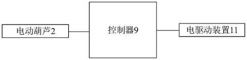
FIG. 3 is a circuit connection diagram of a gantry crane structure according to an embodiment of the present invention;
fig. 4 is a schematic diagram of general control of a gantry crane system provided in an embodiment of the present application.
Description of reference numerals:
100-gantry crane system; 101-a gantry crane; 200-mounting a rail; 300-GIL unit; 1-gantry beam; 2, an electric hoist; 21-a hook; 22-a lifting belt; 3-gantry column; 4-a base; 5-electric hoist rail; 6-a first auxiliary support frame; 7-a second auxiliary support frame; 8-a third auxiliary support frame; 9-a controller; 10-a wheel; 11-an electric drive; 12-a master controller;
Detailed Description
Embodiments of the present invention will be described in detail below with reference to the accompanying drawings.
In the description of the present invention, it is to be understood that the terms "center", "upper", "lower", "front", "rear", "left", "right", "vertical", "horizontal", "top", "bottom", "inner", "outer", and the like indicate orientations or positional relationships based on those shown in the drawings, and are only for convenience of description and simplicity of description, and do not indicate or imply that the referenced devices or elements must have a particular orientation, be constructed and operated in a particular orientation, and thus, are not to be construed as limiting the present invention.
The terms "first", "second" and "first" are used for descriptive purposes only and are not to be construed as indicating or implying relative importance or implicitly indicating the number of technical features indicated. Thus, a feature defined as "first" or "second" may explicitly or implicitly include one or more of that feature. In the description of the present invention, "a plurality" means two or more unless otherwise specified.
In the description of the present invention, it should be noted that, unless otherwise explicitly specified or limited, the terms "mounted," "connected," and "connected" are to be construed broadly, e.g., as meaning either a fixed connection, a removable connection, or an integral connection; can be mechanically or electrically connected; they may be connected directly or indirectly through intervening media, or they may be interconnected between two elements. The specific meanings of the above terms in the present invention can be understood in specific cases to those skilled in the art.
Fig. 1 shows a schematic structural diagram of a gantry crane system provided in an embodiment of the present application, which is used for connecting a plurality of GIL units to form a GIL system. As shown in fig. 1, the gantry crane system 100 includes a plurality of gantry cranes 101, and the plurality of gantry cranes 101 are spaced apart along the extension direction of the installation rail 200 of the GIL system. As shown in fig. 1, the gantry crane system 100 includes two gantry cranes 101, which are spaced apart from each other along the extension direction of the installation rail 200 of the GIL system, and the Y-axis direction in fig. 1 is the extension direction of the installation rail 200 of the GIL system.
The number of the gantry cranes 101 in the gantry crane system 100 may be 2, or 3, 4, or 5 … … the present application does not limit the specific number of the gantry cranes 101, and in practical applications, the number of the gantry cranes 101 may be configured appropriately according to the length or weight of the GIL unit 300.
Fig. 2 shows a schematic structural view of a gantry crane 101 according to an embodiment of the present invention, and as shown in fig. 2, any of the gantry cranes 101 includes: gantry beam 1, electric block 2, gantry column 3 and base 4.
Wherein, the gantry beam 1 is provided with an electric hoist rail 5, the electric hoist 2 is slidably arranged on the electric hoist rail 5, and the X-axis direction shown in fig. 1 and 2 is the sliding direction of the electric hoist 2. Optionally, the material of gantry beam 1 can be i-steel, channel steel, square steel and the like, and the application does not limit the materials. Compared with general section steel (such as square steel, channel steel, round steel and the like), the I-shaped steel has the advantages of low cost, high precision and small residual stress, does not need expensive welding materials and weld joint detection, and can save the manufacturing cost of the steel structure by about 30 percent, so the gantry beam 1 can adopt the I-shaped steel.
In addition, the electric block 2 includes: the lifting belt 22 is connected with the lifting hook 21 and used for lifting the lifting hook 21, the lifting direction of the lifting hook 21 is perpendicular to the sliding direction of the electric hoist 2, the lifting hook 21 is used for connecting the GIL units 300, the lifting hooks 21 of the gantry cranes 101 are used for connecting the same GIL unit 300, and the extending direction of any GIL unit 300 is perpendicular to the gantry beams 1 of the gantry cranes 101. That is, when any of the GIL units 300 is installed, it is possible to complete the installation of the GIL unit 300 by lifting it at different positions of the GIL unit 300 by a plurality of gantry cranes 101.
The Z-axis direction shown in fig. 1 and 2 is the lifting direction of the hook 21. In addition, the above-described "vertical" (i.e., the lifting direction of the hook 21 is perpendicular to the sliding direction of the electric hoist 2, and the extending direction of any GIL unit 300 is perpendicular to the gantry beam 1 of the plurality of gantry cranes 101) may be completely vertical, i.e., at an angle of 90 degrees, or may be nearly vertical, i.e., at an angle of 90 degrees, which is not limited in the present application.
It can be understood that the material of the lifting belt 22 may be a steel wire, and the electric hoist 2 completes the lifting by winding and unwinding the steel wire. Alternatively, the hook 21 may be U-shaped, the size of the U-shaped hook 21 matches the diameter of the GIL unit 300, and the hook 21 may also be a looped steel wire, which is sleeved on the GIL unit 300, which is not limited in this application.
In addition, the gantry upright column 3 is used for supporting the gantry beam 1, and two ends of the gantry beam 1 are respectively connected with the gantry upright column 3; the base 4 is connected to the gantry column 3 to increase the contact area of the gantry crane 101 with the ground. It will be appreciated that when the gantry crane 101 is used to pick up goods, the relatively large load that the gantry crane 101 is subjected to, if the area of the gantry crane 101 in contact with the ground is small, results in a relatively large weight per unit area of ground in contact with the gantry crane 101, which may damage or cause the ground to collapse.
The materials of the gantry upright column 3 and the base 4 can be the same or different. Optionally, the materials of the gantry upright column 3 and the base 4 can be square steel, and can also be channel steel and other section steels, and the application does not limit the materials.
Alternatively, the components (i.e. the gantry upright 3, the base 4, the gantry beam 1, etc.) of the gantry crane 101 can be detachably connected or integrally welded. Due to the fact that the detachable connection is low in transportation cost and simple in installation. Therefore, in order to reduce the difficulty of transportation, assembly and transition, the components of the gantry crane 101 according to the embodiment of the present application are detachably connected, and for example, the components of the gantry crane 101 may be connected by fasteners, which may be screws, bolts, rivets, etc., and the present application is not limited thereto.
The gantry crane system 100 provided by the application comprises a plurality of gantry cranes 101, when the GIL unit 300 is long, the hoisting and installation of the GIL unit 300 can be completed together by using the plurality of gantry cranes 101, because the floor area of a single gantry crane 101 is smaller than that of a large crane (which can also be called a crane), and the gantry cranes 101 are distributed on the installation track 200 at intervals, the area required by the gantry crane system 100 at the construction site is smaller than that of the large crane, and the requirement on the operation area when the GIL unit 300 is installed is reduced.
In addition, as shown in fig. 2, the gantry crane 101 of the present application includes a gantry beam 1, an electric hoist 2, a gantry column 3, and a base 4, and when the GIL unit 300 is installed, the GIL unit 300 is connected by a hook 21 on the electric hoist 2, the vertical displacement of the GIL unit 300 is completed by a lifting belt 22, the horizontal displacement of the GIL unit 300 is completed by the displacement of the electric hoist 2 on an electric hoist rail 5, and when the GIL unit 300 is hooked up by the hook 21 on the electric hoist 2, the gantry beam 1 bears the weight of the GIL unit 300. Because the two ends of the gantry beam 1 are respectively connected with the gantry columns 3, and the lower ends of the gantry columns 3 at the two ends are respectively connected with the base 4, the gravity of the GIL unit 300 born by the gantry beam 1 is transferred to the base 4 and acts on the ground by the base 4. Furthermore, since the single GIL unit 300 is long and the hooks 21 of the plurality of gantry cranes 101 are connected to the GIL unit 300, the hung GIL unit 300 can be kept balanced and the GIL unit 300 can be installed, and the hooks 21 of the gantry crane system 100 move only within the range of the installation rail 200 of the GIL unit 300, so that the range of motion of the hooks 21 is small and the working height of the hooks 21 is low, and it is safe to install the GIL unit 300 using the gantry crane system 100 when a charged body exists near the working surface of the construction site.
The structure of the gantry crane 101 will be further described below by taking the gantry crane 101 according to the embodiment of the present invention as an example.
In some embodiments, the electric hoist 2 may be a chain-type electric hoist, which has the advantages of compact structure, small volume, light weight, high efficiency, convenient use, reliable braking, simple maintenance, etc. Thus, when the electric hoist 2 of the gantry crane 101 is used to mount the GIL unit 300, since the brake of the chain type electric hoist is reliable, the mounting height of the GIL unit 300 can be controlled to accurately mount the GIL unit 300 when the GIL unit 300 is mounted.
In other embodiments, the electric hoist 2 can be a steel wire rope electric hoist, and the steel wire rope electric hoist has the advantages of stable operation, simple operation, convenient use and the like. When the electric block 2 of the gantry crane 101 is installing the GIL unit 300, the wire rope electric block can stably hoist the GIL unit 300 and complete the installation because the wire rope electric block operates stably.
The electric block 2 of the embodiment of the present application is preferably a chain type electric block because the precision requirement for the installation of the GIL unit 300 is high.
It will be appreciated that the electric block 2 typically includes a first motor therein that powers the raising and lowering of the lift belt 22 and the sliding of the electric block 2 on the electric block track 5. When the operation speed of the electric hoist 2 is fast (i.e., the lifting speed of the lifting belt 22 or the sliding speed of the electric hoist 2 on the electric hoist rail 5), since the precision requirement of the GIL unit 300 installation is high, it takes a lot of time to adjust the position of the lifted GIL unit 300 to ensure the accurate docking of the GIL unit 300. Therefore, in order to solve this problem, in some embodiments, the first motor is an inverter motor, and the inverter motor can realize stepless speed change, so that the lifting of the lifting belt 22 and the sliding speed of the electric hoist 2 on the electric hoist rail 5 can be controlled. Thus, when the gantry crane 101 is used for installing the GIL unit 300, the motor can be regulated to be in a low-rotation-speed mode, so that the installation and butt joint of the GIL unit 300 are stable and smooth, and the working efficiency is improved.
In other embodiments, GIL cell 300 is a 500 kv GIL cell 300. The gantry crane system 100 of the embodiment of the present application can install 500 kv GIL units 300 to constitute a 500 kv GIL system.
In some embodiments, GIL cell 300 is a 1000 kv GIL cell 300. It can be understood that the length of the 1000 kv GIL unit 300 is 18 meters, and since the 1000 kv GIL unit 300 is too long and troublesome to install, the embodiment of the present invention can be matched by a plurality of gantry cranes 101 to complete the installation of the GIL system 100.
In practical applications, when the portal crane 101 lifts the GIL unit 300, the load borne by the portal beam 1 of the portal crane 101 is large, which causes the load borne by the portal column 3 supporting the portal beam 1 to be large, which further causes the portal column 3 to tilt, and even more, the portal column 3 to collapse.
Therefore, in order to ensure the stability of the gantry upright column 3, the bearing capacity of the gantry upright column 3 is improved. In some embodiments, the gantry crane 101 further comprises a first auxiliary support frame 6, one end of the first auxiliary support frame 6 is connected to the gantry column 3, the other end of the first auxiliary support frame 6 is connected to the base 4, and the first auxiliary support frame 6 forms a triangle with the gantry column 3 and the base 4. In this way, the first auxiliary support frame 6 connects the gantry column 3 and the base 4 to form a triangular structure, and the stability of the gantry column 3 can be improved and the service life of the gantry crane 101 can be prolonged due to the good stability of the triangular structure.
In other embodiments, the gantry crane 101 further comprises: one end of the second auxiliary support frame 7 is connected with the gantry upright column 3, the other end of the second auxiliary support frame 7 is connected with the base 4, and the first auxiliary support frame 6, the second auxiliary support frame 7 and the base 4 form an isosceles triangle. Thus, the stability of the gantry column 3 is further enhanced, and the stable operation of the gantry crane 101 is further ensured.
In addition, in order to ensure the connection stability between the gantry beam 1 and the gantry column 3, in some embodiments, the gantry crane 101 further includes: and one end of the third auxiliary support frame 8 is connected with the gantry beam 1, the other end of the third auxiliary support frame 8 is connected with the gantry upright post 3, and the third auxiliary support frame 8, the gantry beam 1 and the gantry upright post 3 form a triangle. In this way, the third auxiliary support frame 8 indirectly connects the gantry beam 1 and the gantry column 3, and further enhances the stability of the connection between the gantry beam 1 and the gantry column 3.
Fig. 3 is a circuit connection diagram illustrating a gantry crane structure according to an embodiment of the present invention, and as shown in fig. 3, the gantry crane 101 further includes: and the controller 9, the controller 9 is electrically connected with the electric hoist 2, and the controller 9 is used for controlling the movement of the electric hoist 2 on the electric hoist track 5. In this way, the controller 9 can control the electric hoist 2 to move on the electric hoist rail 5, so as to control the GIL unit 300 lifted by the hook 21 to move in the horizontal direction, thereby facilitating the installation of the GIL unit 300.
In another possible implementation, the controller 9 is also used to control the lifting of the hook 21. In this way, the controller 9 can control the lifting and lowering of the hook 21, thereby controlling the GIL unit 300 lifted by the hook 21 to move in the vertical direction, and improving the installation efficiency.
In yet another possible implementation, the controller 9 can be used to control the movement of the electric block 2 on the electric block rail 5 and the lifting of the hook 21. Therefore, the controller 9 can control the horizontal movement and the vertical movement of the GIL unit 300 lifted by the hook 21, and in the process, workers do not need to participate in regulating and controlling the position of the GIL unit 300, so that the labor is saved.
Therein, it is understood that in some embodiments, the electrical connection between the controller 9 and the electric hoist 2 may be a wireless electrical connection, that is, the connection between the controller 9 and the electric hoist 2 is realized by wireless signals. Therefore, a worker can remotely control the movement of the electric hoist 2 through the controller 9, and the installation of the worker is facilitated.
In other embodiments, the electrical connection between the controller 9 and the electric hoist 2 may be a wired electrical connection, i.e., the connection between the controller 9 and the electric hoist 2 is realized by a wire. Therefore, the connection between the controller 9 and the electric hoist 2 is stable, and the controller 9 is not easily interfered by external factors (such as a magnetic field, solar black sub activities, and the like) in the process of controlling the operation of the electric hoist 2.
In addition, the controller 9 may be composed of a plurality of chips, and the controller 9 may also be composed of one integrated chip, which is not limited in this application.
Since it is necessary to connect a plurality of GIL units 300 one by one through the gantry system 100 during the installation of the GIL system 100. For example, after one GIL unit 300 is installed using the gantry crane system 100 at the first position of the installation rail 200, it is necessary to move the plurality of gantry cranes 101 of the gantry crane system 100 to the second position of the installation rail 200 and continue to install another GIL unit 300. Accordingly, it is necessary to move the gantry crane 101 several times during the actual installation process, and it takes much time and effort for a worker to move the gantry crane 101.
To address this problem, in some embodiments, as shown in FIG. 2, the gantry 101 further comprises wheels 10, the wheels 10 being connected to the base 4, the wheels 10 enabling the gantry 101 to move on the mounting rail 200. Therefore, workers can push the gantry crane 101 to move the gantry crane 101, physical strength is saved, and the use of the workers is facilitated.
The wheels 10 may be universal wheels, so that the gantry crane 101 can move in multiple directions, and the use by workers is convenient.
In order to prevent the wheels 10 from rotating during the lifting of the GIL unit 300 by the gantry crane 101, thereby causing the gantry crane 101 to slide, resulting in the problem that the GIL unit 300 cannot be smoothly installed. Thus, in some embodiments, the wheel 10 is also provided with a brake device that prevents the wheel 10 from rotating. This improves the stability of the gantry crane 101 and prevents the wheels 10 from rotating during the lifting of the gantry crane 101 from the GIL unit 300.
Wherein, this brake equipment can the brake calliper, also can be for brake block and brake drum etc. this application does not limit to this.
To further facilitate the installation for workers, in some embodiments, as shown in fig. 2, the gantry crane 101 further includes an electric drive 11, the electric drive 11 is mounted on the base 4, and the electric drive 11 is connected to the wheels 10 for driving the wheels 10 to rotate. Therefore, when the gantry crane 101 needs to be moved, the electric driving device 11 can provide power, the pushing by workers is not needed, and the manpower is saved.
Wherein the electric drive 11 may comprise: a second motor and a transmission device, i.e. the second motor drives the wheels 10 to rotate through the transmission device, so that the gantry crane 101 moves. The power of the second motor may be 1000kw or 1200kw, and the power of the second motor is not limited in this application.
In some embodiments, as shown in fig. 3, the controller 9 is also electrically connected to the electric drive 11, and the controller 9 controls the electric drive 11 to be turned on or off. Thus, a worker can control the movement of the gantry crane 101 through the controller 9, facilitating the installation of the GIL unit 300.
The electrical connection between the controller 9 and the electric driving device 11 may be a wired electrical connection or a wireless electrical connection, and reference may be made to the description of the electrical connection between the controller 9 and the electric hoist 2, which is not described herein again.
In order to ensure the installation accuracy of the GIL unit 300 during the installation of the GIL unit 300, a plurality of gantry cranes 101 are required to perform together in cooperation (e.g., synchronous horizontal displacement or synchronous vertical displacement of the hooks 21 of a plurality of gantry cranes 101).
Therefore, in order to synchronize the motion states of a plurality of gantry cranes 101 (e.g., the movement of the electric hoist 2 on the electric hoist rail 5, the lifting of the hook 21, and the movement of the wheels 10 driven by the electric drive device 11), fig. 4 illustrates an overall control diagram of the gantry crane system provided by the embodiment of the present application, and as shown in fig. 4, the gantry crane system 100 further includes an overall controller 12. The general controller 12 is electrically connected with the electric hoists 2 and the electric drives 11 of the multiple portal cranes 101, and the general controller 12 can control the electric hoists 2 of the multiple portal cranes 101 to synchronously move on the electric hoist track 5 and is used for controlling the lifting hooks 21 of the multiple portal cranes 101 to synchronously lift and control the electric drives 11 of the multiple portal cranes 101 to synchronously start or stop. Thus, the movement states of the plurality of gantry cranes 101 can be controlled simultaneously, and the docking accuracy of the GIL unit 300 can be improved.
It can be understood that the electric connection between the main controller 12 and the electric hoists 2 of the plurality of gantry cranes 101 may be a wireless electric connection or a wired electric connection, and the description of the present application is omitted.
In addition, the overall controller 12 may also be composed of a plurality of chips, and the overall controller 12 may also be composed of one integrated chip, which is not limited in this application.
In addition, the general controller 12 described above can control the motion states of three positions of the plurality of gantry cranes 101 (i.e., (i) the electric block 2 moves on the electric block rail 5, (ii) the lifting hook 21 is lifted, (iii) the electric drive 11 drives the wheels 10 to move). In some embodiments, the general controller 12 controls the motion status of two positions of the plurality of gantry cranes 101. For example, the master controller 12 controls the movement of the electric hoist 2 on the electric hoist rail 5 and the lifting of the hook 21; or the master controller 12 controls the lifting of the lifting hook 2 and the electric driving device 11 to drive the wheels 10 to move; alternatively, the general controller 12 controls the movement of the electric block 2 on the electric block rail 5 and the movement of the electric driving device 11 driving the wheels 10.
In other embodiments, the general controller 12 controls the movement of one position of a plurality of gantry cranes 101. For example, the general controller 12 controls the movement of the electric block 2 on the electric block rail 5; or, the master controller 12 controls the lifting of the hook 21; alternatively, the general controller 12 controls the electric driving device 11 to drive the wheel 10 to rotate, which is not limited in this application.
In the description herein, particular features, structures, materials, or characteristics may be combined in any suitable manner in any one or more embodiments or examples.
The above description is only for the specific embodiments of the present invention, but the scope of the present invention is not limited thereto, and any person skilled in the art can easily conceive of the changes or substitutions within the technical scope of the present invention, and all the changes or substitutions should be covered within the scope of the present invention. Therefore, the protection scope of the present invention shall be subject to the protection scope of the appended claims.
Claims (8)
1. A gantry crane system for linking gas insulated metal enclosed transmission busbar GIL units to form a GIL system, said gantry crane system comprising a plurality of gantry cranes spaced apart along the extension of the mounting rails of said GIL system, any of said gantry cranes comprising:
the gantry beam is provided with an electric hoist track;
electric block, electric block slides and sets up on the electric block track, electric block includes: the lifting belt is connected with the lifting hook and used for lifting the lifting hook, the lifting direction of the lifting hook is perpendicular to the sliding direction of the electric hoist, the lifting hook is used for connecting the GIL units, a plurality of lifting hooks of the gantry cranes are used for connecting the same GIL unit, and the extension direction of any GIL unit is perpendicular to the gantry beams of the gantry cranes;
the gantry upright post is used for supporting the gantry beam, and two ends of the gantry beam are respectively connected with the gantry upright post;
and the base is connected with the gantry upright column.
2. The gantry crane system of claim 1, wherein any of said gantry cranes further comprises:
the controller, the controller with electric block electricity is connected, the controller is used for control electric block is in move on the electric block track, and be used for control the lifting hook goes up and down.
3. The gantry crane system of claim 2, wherein any of said gantry cranes further comprises:
wheels connected with the base, the wheels being used for moving the gantry crane on the mounting rail;
the electric drive device is installed on the base and connected with the wheels and used for driving the wheels to rotate.
4. The gantry crane system of claim 3 wherein said controller is further electrically connected to said electric drive, said controller controlling said electric drive to turn on or off.
5. The gantry crane system of claim 3, further comprising:
the general controller is electrically connected with the electric hoists and the electric driving device of the gantry cranes, and is used for controlling the electric hoists of the gantry cranes to synchronously move on the electric hoist track, controlling the lifting hooks of the gantry cranes to synchronously lift and controlling the electric driving device of the gantry cranes to synchronously start or stop.
6. A gantry crane system according to any one of claims 1-5, wherein said electric hoist of any one of said gantry cranes is a chain-type electric hoist.
7. The gantry crane system of claim 1, wherein any of said gantry cranes further comprises:
one end of the first auxiliary support frame is connected with the gantry upright column, the other end of the first auxiliary support frame is connected with the base, and the first auxiliary support frame, the gantry upright column and the base form a triangle.
8. The gantry crane system of claim 7, wherein any of said gantry cranes further comprises:
one end of the second auxiliary support frame is connected with the gantry upright column, the other end of the second auxiliary support frame is connected with the base, and the first auxiliary support frame, the second auxiliary support frame and the base form an isosceles triangle.
Priority Applications (1)
| Application Number | Priority Date | Filing Date | Title |
|---|---|---|---|
| CN202220339928.2U CN216889795U (en) | 2022-02-18 | 2022-02-18 | Gantry crane system for GIL installation |
Applications Claiming Priority (1)
| Application Number | Priority Date | Filing Date | Title |
|---|---|---|---|
| CN202220339928.2U CN216889795U (en) | 2022-02-18 | 2022-02-18 | Gantry crane system for GIL installation |
Publications (1)
| Publication Number | Publication Date |
|---|---|
| CN216889795U true CN216889795U (en) | 2022-07-05 |
Family
ID=82185443
Family Applications (1)
| Application Number | Title | Priority Date | Filing Date |
|---|---|---|---|
| CN202220339928.2U Active CN216889795U (en) | 2022-02-18 | 2022-02-18 | Gantry crane system for GIL installation |
Country Status (1)
| Country | Link |
|---|---|
| CN (1) | CN216889795U (en) |
-
2022
- 2022-02-18 CN CN202220339928.2U patent/CN216889795U/en active Active
Similar Documents
| Publication | Publication Date | Title |
|---|---|---|
| CN110023230B (en) | Overhead travelling crane | |
| CN111711117A (en) | Special equipment is strideed across to reliability | |
| CN114852883A (en) | Hoisting device and control system thereof | |
| CN216889795U (en) | Gantry crane system for GIL installation | |
| CN102730585B (en) | Series compensation platform hydraulic installation system with level adjustment function | |
| CN114408756A (en) | Gantry crane system for GIL installation | |
| CN210031529U (en) | Automatic climbing platform for construction of hanging cable | |
| CN106081901A (en) | A kind of novel SMD hoisting trolley | |
| CN210855029U (en) | Steel box girder component construction vehicle for high-altitude transportation and hoisting operation | |
| CN212503702U (en) | Movable safety belt hanging point device for aerial work | |
| CN205151579U (en) | Two horizontal arm hoists | |
| CN201660377U (en) | Special gantry crane for overlength and large-tonnage parts | |
| CN114476952A (en) | Method for installing GIL unit by using gantry crane system | |
| CN219409025U (en) | Simple and easy track district heavy object hoisting device | |
| CN111717794A (en) | Self-propelled trolley and crane | |
| CN216272670U (en) | Hoisting member | |
| CN217947600U (en) | Dolly is installed to earth connection | |
| CN105271009A (en) | Double-horizontal-boom crane | |
| CN216512495U (en) | Special bridge crane for steel mill metallurgy | |
| CN216512468U (en) | A assembled slide-wire pole for supporting a quick-witted slide-wire of door | |
| CN212953965U (en) | Upper shaft crown block for processing metal section | |
| CN213294467U (en) | Tower crane that structural strength is high | |
| CN214269986U (en) | Connection steel structure for building construction | |
| CN215971195U (en) | Upright post lifting and inclining driving device and lifting hidden type movable contact net | |
| CN217264328U (en) | Top supporting structure based on truss girder and gravity energy storage system |
Legal Events
| Date | Code | Title | Description |
|---|---|---|---|
| GR01 | Patent grant | ||
| GR01 | Patent grant | ||
| PP01 | Preservation of patent right | ||
| PP01 | Preservation of patent right |
Effective date of registration: 20231024 Granted publication date: 20220705 |
|
| PD01 | Discharge of preservation of patent | ||
| PD01 | Discharge of preservation of patent |
Date of cancellation: 20240117 Granted publication date: 20220705 |