CN216883387U - Grinding wheel dressing device - Google Patents
Grinding wheel dressing device Download PDFInfo
- Publication number
- CN216883387U CN216883387U CN202220954788.XU CN202220954788U CN216883387U CN 216883387 U CN216883387 U CN 216883387U CN 202220954788 U CN202220954788 U CN 202220954788U CN 216883387 U CN216883387 U CN 216883387U
- Authority
- CN
- China
- Prior art keywords
- pull rod
- shell
- dresser
- ram
- rotatably connected
- Prior art date
- Legal status (The legal status is an assumption and is not a legal conclusion. Google has not performed a legal analysis and makes no representation as to the accuracy of the status listed.)
- Active
Links
Images

Abstract
The utility model discloses a grinding wheel dressing device which comprises a rack, wherein a shell is fixedly arranged on the front surface of the rack, a dresser seat is fixedly arranged on one side of the middle part of the front surface of the shell, a speed reducing motor is fixedly arranged on one side of the rack far away from the dresser seat, an output end of the speed reducing motor is fixedly connected with an eccentric sleeve, a joint bearing is fixedly arranged on one side of the front surface of the eccentric sleeve, the surface of the joint bearing is rotatably connected with a first hinge shaft, a ram is slidably connected inside the dresser seat, a diamond dressing block is fixedly arranged on the surface of the ram, one end of the ram is rotatably connected with a round pull rod, and one end of the round pull rod is rotatably connected with a square pull rod.
Description
Technical Field
The utility model relates to the field of steel ball processing and grinding, in particular to a grinding wheel dressing device.
Background
Dressing of the wheel is an operation in which the wheel is dressed to shape or to remove a dull finish with a dressing tool to restore the grinding performance and correct geometry of the working surface.
The grinding wheel dresser used in the processing of the common steel ball is a hydraulic dresser, a hydraulic cylinder is driven, but due to the structural limitation of a machine tool, the space for installing the dresser is very small, the cylinder diameter of the used hydraulic cylinder is small, the corresponding working pressure is large, because the hydraulic dresser is installed near a grinding area, the temperature is high, the humidity is large, a sealing ring is easy to age, hydraulic oil is easy to leak from the oil cylinder, the hydraulic oil is mixed into grinding fluid, the cutting force is insufficient, and the quality of a steel ball product is influenced, so that the grinding wheel dresser is provided.
SUMMERY OF THE UTILITY MODEL
The utility model aims to provide a grinding wheel dressing device to solve the problems that the prior dressing device provided by the background technology has small space for installing a dresser, the diameter of a used hydraulic cylinder is small, the corresponding working pressure is high, a sealing ring is easy to age due to the fact that the hydraulic dressing device is installed near a grinding area, the temperature is high, the humidity is high, hydraulic oil is easy to leak from the oil cylinder, and the quality of a steel ball product is influenced.
In order to achieve the purpose, the utility model provides the following technical scheme: the grinding wheel dressing device comprises a rack, wherein a shell is fixedly mounted on the front side of the rack, a dresser seat is fixedly mounted on one side of the middle of the front side of the shell, a speed reduction motor is fixedly mounted on one side, away from the dresser seat, of the rack, an eccentric sleeve is fixedly connected to the output end of the speed reduction motor, a joint bearing is fixedly mounted on one side of the front side of the eccentric sleeve, a first hinge shaft is connected to the surface of the joint bearing in a rotating mode, a ram is connected to the interior of the dresser seat in a sliding mode, a diamond dressing block is fixedly mounted on the surface of the ram, a round pull rod is connected to one end of the ram in a rotating mode, a square pull rod is connected to one end of the round pull rod in a rotating mode, a second hinge shaft is fixedly connected to one end of the square pull rod, and the first hinge shaft is hinged to the second hinge shaft.
When the grinding wheel dressing device adopting the technical scheme is used, the dresser drives the eccentric sleeve to rotate by the speed reduction motor, so that the knuckle bearing and the two hinge shafts are driven to pull the square pull rod and the round pull rod, and finally the diamond dressing block on the ram is driven to continuously reciprocate.
According to a preferable technical scheme of the utility model, a fan is fixedly installed on one side of the top of the front face of the rack, a dust collection box is fixedly communicated with the output end of the fan, an air outlet is formed in one side of the dust collection box, which is far away from the speed reduction motor, and a filter screen is clamped on the surface of the air outlet. The dust removal and chipping functions are achieved through the fan.
As a preferred technical scheme of the utility model, the input end of the fan is fixedly connected with a dust hood. The dust hood is convenient for collecting dust.
As a preferable technical scheme of the utility model, the top of the shell close to one side of the dresser seat is provided with a ball inlet. The ball inlet is used for placing a steel ball.
As a preferable technical scheme of the utility model, the bottom of the shell close to one side of the dresser seat is provided with a ball outlet. The ball outlet is used for discharging the steel balls.
As a preferable technical scheme of the utility model, the bottom end of the square pull rod is fixedly provided with a limiting bearing, and the limiting bearing is rotatably connected with the shell. The limiting bearing can limit the position of the square pull rod.
As a preferable technical scheme of the utility model, the diamond trimming block is provided with a plurality of diamond trimming blocks. The repairing effect of a plurality of diamond repairing blocks is better.
Compared with the prior art, the utility model has the beneficial effects that:
1. the trimmer is arranged between the ball inlet and the ball outlet, and the eccentric sleeve is driven to rotate by the speed reducing motor, so that the knuckle bearing and the two hinge shafts are driven to pull the square pull rod and the round pull rod, and finally the diamond trimming block on the ram is driven to continuously reciprocate to perform trimming work, so that the problem that the quality of a steel ball product is influenced by hydraulic oil leakage is solved;
2. the fan that sets up can inhale the raise dust piece that produces when repairing, and inspiratory wind is discharged from the air outlet, and dust and piece can be deposited in the suction hood under the obstruction of filter screen, and the clearance is more convenient.
Drawings
FIG. 1 is a perspective view of the present invention;
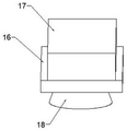
FIG. 2 is a perspective view of the blower of the present invention;
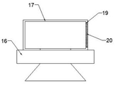
fig. 3 is a sectional view of the blower of the present invention.
In the figure: 1. a frame; 2. a housing; 3. a dresser seat; 4. a reduction motor; 5. an eccentric sleeve; 6. a knuckle bearing; 7. a first hinge axis; 8. a ram; 9. a diamond trimming block; 10. a round pull rod; 11. a square pull rod; 12. a second hinge axis; 13. a ball inlet; 14. a ball outlet; 15. a limit bearing; 16. a fan; 17. a dust collecting box; 18. a dust hood; 19. an air outlet; 20. and (5) filtering by using a filter screen.
Detailed Description
The technical solutions in the embodiments of the present invention will be clearly and completely described below with reference to the drawings in the embodiments of the present invention, and it is obvious that the described embodiments are only a part of the embodiments of the present invention, and not all of the embodiments. All other embodiments, which can be derived by a person skilled in the art from the embodiments given herein without making any creative effort, shall fall within the protection scope of the present invention.
Referring to fig. 1-3, the present invention provides a grinding wheel dressing device, including a frame 1, a housing 2 is fixedly installed on the front of the frame 1, a dresser seat 3 is fixedly installed on one side of the middle of the front of the housing 2, a reduction motor 4 is fixedly installed on one side of the frame 1 far from the dresser seat 3, an output end of the reduction motor 4 is fixedly connected with an eccentric sleeve 5, a knuckle bearing 6 is fixedly installed on one side of the front of the eccentric sleeve 5, a first hinge shaft 7 is rotatably connected to the surface of the knuckle bearing 6, a ram 8 is slidably connected to the interior of the dresser seat 3, a diamond dressing block 9 is fixedly installed on the surface of the ram 8, the dressing work is performed by reciprocating the diamond dressing block 9, one end of the ram 8 is rotatably connected with a circular pull rod 10, one end of the circular pull rod 10 is rotatably connected with a square pull rod 11, one end of the square pull rod 11 is fixedly connected with a second hinge shaft 12, the first hinge shaft 7 is hinged with the second hinge shaft 12 to play a role in transmission.
When the device is used, the eccentric sleeve 5 is driven to rotate by the speed reducing motor 4, so that the oscillating bearing 6 and the two hinge shafts are driven to pull the square pull rod 11 and the round pull rod 10, and finally the diamond trimming block 9 on the ram 8 is driven to continuously reciprocate to perform trimming work, so that the problem that the quality of a steel ball product is influenced by hydraulic oil leakage is solved as compared with a hydraulic trimmer, the speed reducing motor 4 is controlled by frequency conversion, and the speed can be adjusted steplessly;
a fan 16 is fixedly installed on one side of the top of the front face of the rack 1 to play a role in dust removal, the output end of the fan 16 is fixedly communicated with a dust collection box 17, an air outlet 19 is formed in one side, away from the speed reduction motor 4, of the dust collection box 17, a filter screen 20 is clamped on the surface of the air outlet 19, and the input end of the fan 16 is fixedly connected with a dust hood 18 to facilitate dust collection;
when the dust collector is used, the arranged fan 16 can suck the raised dust and debris generated during trimming through the dust hood 18, the sucked wind is discharged from the air outlet 19, and the dust and the debris can be retained in the dust hood 18 for storage under the obstruction of the filter screen 20, so that the cleaning is more convenient;
the top of one side, close to the dresser seat 3, of the shell 2 is provided with a ball inlet 13, the bottom of one side, close to the dresser seat 3, of the shell 2 is provided with a ball outlet 14 for the entry and exit of steel balls, the bottom end of the square pull rod 11 is fixedly provided with a limiting bearing 15, the limiting bearing 15 is rotatably connected with the shell 2 to play a limiting role, the diamond trimming blocks 9 are provided with a plurality of diamond trimming blocks, and the trimming effect is better;
during the use, the ball inlet 13 and the ball outlet 14 that set up are used for the entering and the discharge of steel ball respectively, provide power for the trimmer through gear motor 4, and the horizontal motion about square pull rod 11 can be made to spacing bearing 15 that sets up during the motion, makes the continuous reciprocating motion of a plurality of diamond trimming piece 9, carries out the trimming work.
When the grinding wheel dressing device is used, a dresser is arranged between a ball inlet 13 and a ball outlet 14, the reduction motor 4 drives the eccentric sleeve 5 to rotate, so that the knuckle bearing 6 and the two hinge shafts are driven to pull the square pull rod 11 and the round pull rod 10, and finally the diamond dressing block 9 on the ram 8 is driven to move continuously and reciprocally to carry out dressing work, the problem that the quality of a steel ball product is affected due to leakage of hydraulic oil is solved as compared with a hydraulic dresser, the reduction motor 4 is controlled in a variable frequency mode, the speed can be adjusted in a stepless mode, a fan 16 can suck flying dust and debris generated during dressing, sucked air is discharged from an air outlet 19, dust and debris can be retained in a dust hood 18 under the blocking of a filter screen 20 and stored, and the dressing is more convenient to clean.
Although the present invention has been described in detail with reference to the foregoing embodiments, it will be apparent to those skilled in the art that various changes in the embodiments and/or modifications of the utility model can be made, and equivalents and modifications of some features of the utility model can be made without departing from the spirit and scope of the utility model.
Claims (7)
1. A grinding wheel dressing device comprises a machine frame (1), and is characterized in that: the front of the rack (1) is fixedly provided with a shell (2), one side of the middle part of the front of the shell (2) is fixedly provided with a dresser seat (3), one side of the rack (1) far away from the dresser seat (3) is fixedly provided with a speed reducing motor (4), the output end of the speed reducing motor (4) is fixedly connected with an eccentric sleeve (5), one side of the front of the eccentric sleeve (5) is fixedly provided with a joint bearing (6), the surface of the joint bearing (6) is rotatably connected with a first hinge shaft (7), the interior of the dresser seat (3) is slidably connected with a ram (8), the surface of the ram (8) is fixedly provided with a diamond trimming block (9), one end of the ram (8) is rotatably connected with a circular pull rod (10), one end of the circular pull rod (10) is rotatably connected with a square pull rod (11), one end of the square pull rod (11) is fixedly connected with a second hinge shaft (12), the first hinge shaft (7) is hinged with the second hinge shaft (12).
2. The wheel truing apparatus according to claim 1, wherein: the fan (16) is fixedly mounted on one side of the top of the front face of the rack (1), the output end of the fan (16) is fixedly communicated with a dust collection box (17), an air outlet (19) is formed in one side, away from the speed reduction motor (4), of the dust collection box (17), and a filter screen (20) is clamped on the surface of the air outlet (19).
3. The wheel truing apparatus according to claim 2, wherein: the input end of the fan (16) is fixedly connected with a dust hood (18).
4. The wheel truing apparatus according to claim 1, wherein: the top of one side of the shell (2) close to the dresser seat (3) is provided with a ball inlet (13).
5. The wheel truing apparatus according to claim 1, wherein: the bottom of one side of the shell (2) close to the dresser seat (3) is provided with a ball outlet (14).
6. The wheel truing apparatus according to claim 1, wherein: the bottom end of the square pull rod (11) is fixedly provided with a limiting bearing (15), and the limiting bearing (15) is rotatably connected with the shell (2).
7. The wheel truing apparatus according to claim 1, wherein: the diamond trimming block (9) is provided with a plurality of blocks.
Priority Applications (1)
| Application Number | Priority Date | Filing Date | Title |
|---|---|---|---|
| CN202220954788.XU CN216883387U (en) | 2022-04-24 | 2022-04-24 | Grinding wheel dressing device |
Applications Claiming Priority (1)
| Application Number | Priority Date | Filing Date | Title |
|---|---|---|---|
| CN202220954788.XU CN216883387U (en) | 2022-04-24 | 2022-04-24 | Grinding wheel dressing device |
Publications (1)
| Publication Number | Publication Date |
|---|---|
| CN216883387U true CN216883387U (en) | 2022-07-05 |
Family
ID=82193709
Family Applications (1)
| Application Number | Title | Priority Date | Filing Date |
|---|---|---|---|
| CN202220954788.XU Active CN216883387U (en) | 2022-04-24 | 2022-04-24 | Grinding wheel dressing device |
Country Status (1)
| Country | Link |
|---|---|
| CN (1) | CN216883387U (en) |
-
2022
- 2022-04-24 CN CN202220954788.XU patent/CN216883387U/en active Active
Similar Documents
| Publication | Publication Date | Title |
|---|---|---|
| CN209021775U (en) | A kind of polishing machine with dust cleaning ability | |
| CN208811805U (en) | A kind of grinding machine with automatic clearing function | |
| CN214418454U (en) | Rust removal and grinding device for steel templates | |
| CN112108883A (en) | Adjustable automatic cutting and polishing equipment for alloy pipeline | |
| CN209548938U (en) | A kind of grinding machine air cleaning unit | |
| CN216883387U (en) | Grinding wheel dressing device | |
| CN216967334U (en) | Zinc-plating almag steel slab band grinding device | |
| CN110696101A (en) | Numerical control band saw machine that has dust removal function | |
| CN114750035A (en) | Polishing device and polishing method for metal part machining | |
| CN114074277A (en) | Polishing device for aluminum alloy machining and machining method | |
| CN214237668U (en) | Production of industry stainless steel pipe is with burnishing machine that has dust collection structure | |
| CN214024948U (en) | Glass apron edging device with dust removal effect | |
| CN112454054A (en) | Equipment capable of adjusting angle for cutting underground water pipe | |
| CN108747776B (en) | High-efficient burnishing machine with dust absorption function | |
| CN208409476U (en) | Grinding machine is used in a kind of machining of environment-friendly type | |
| CN215700489U (en) | Precision grinding machine is used in processing of accurate accessories | |
| CN208409497U (en) | A kind of new ceramics grinding device | |
| CN218051890U (en) | Constant head tank grinding subassembly | |
| CN219074584U (en) | Gear hobbing machine | |
| CN219967597U (en) | Grinding wheel dressing mechanism of bearing ring grinding machine | |
| CN220533841U (en) | Grinding machine with dust recycling function | |
| CN219901429U (en) | Automatic coping device is used in carton printing | |
| CN218254423U (en) | Grinding machine with dustproof effect | |
| CN214135285U (en) | Edge grinding device for machining wave-shaped highway guardrail plate | |
| CN220145378U (en) | Cleaning device for building model engraving machine |
Legal Events
| Date | Code | Title | Description |
|---|---|---|---|
| GR01 | Patent grant | ||
| GR01 | Patent grant |