CN216843014U - Wear-resistant gear box - Google Patents
Wear-resistant gear box Download PDFInfo
- Publication number
- CN216843014U CN216843014U CN202121045806.4U CN202121045806U CN216843014U CN 216843014 U CN216843014 U CN 216843014U CN 202121045806 U CN202121045806 U CN 202121045806U CN 216843014 U CN216843014 U CN 216843014U
- Authority
- CN
- China
- Prior art keywords
- base
- gear box
- box body
- wear
- group
- Prior art date
- Legal status (The legal status is an assumption and is not a legal conclusion. Google has not performed a legal analysis and makes no representation as to the accuracy of the status listed.)
- Active
Links
Images


Landscapes
- Vibration Prevention Devices (AREA)
Abstract
The utility model relates to the technical field of mechanical rotating equipment, in particular to a wear-resistant gear box; the base is located the top of base, the both sides limit of base has the recess, damper's quantity is two sets of, every group damper is located the groove respectively, the gear box body is located the top of base, the side of gear box body has the mounting groove, the holding ring is located mounting groove department, positioning component's quantity is two sets of, every group positioning component is located the both sides limit of holding ring respectively, damper through base both sides limit, shock attenuation is carried out to the base, thereby just, the gear box body is cushioned, just, two sets of damper can be assisted to two sets of positioning component of gear box body side, carry out the shock attenuation to its gear box body, strengthen damper's shock attenuation effect, just, be difficult for causing the not hard up of part, damage deformation, thereby prolong its life.
Description
Technical Field
The utility model relates to a machinery rotating equipment technical field especially relates to a stand wear and tear gear box.
Background
Gearboxes are used in a wide range of applications, for example in wind power installations, where gearboxes are an important mechanical component. The wind power generator mainly has the function of transmitting the power generated by the wind wheel under the action of wind power to the generator and enabling the generator to obtain corresponding rotating speed. The speed of the wind wheel is usually very low, and the speed of the wind wheel is far less than the speed required by the generator to generate electricity, and the speed is increased by the speed increasing action of a gear pair of the gearbox, so the gearbox is also called as a speed increasing box.
When gears in the existing gear box operate, vibration is easy to generate, and when the vibration is large, parts of all parts are easy to loosen, damage and deform, so that the service life of the gear box is influenced.
SUMMERY OF THE UTILITY MODEL
An object of the utility model is to provide a stand wear and tear gear box, when aiming at solving the inside gear function of gear box among the prior art, easily produce vibrations, when vibrations are great, easily cause each position part not hard up, damage deformation to influence its life's technical problem.
In order to achieve the purpose, the wear-resistant gear box adopted by the utility model comprises a base, a damping component, a base, a gear box body, a positioning ring and a positioning component, wherein the base is movably connected with the base, and is positioned above the base, grooves are arranged on two side edges of the base, the number of the shock absorption components is two, each group of the shock absorption components is respectively and fixedly connected with the base, and are respectively positioned at the grooves, the gear box body is fixedly connected with the base and positioned above the base, the side edge of the gear box body is provided with an installation groove, the positioning ring is movably connected with the gear box body, the positioning assemblies are arranged at the mounting groove, the number of the positioning assemblies is two, and each group of the positioning assemblies is respectively movably connected with the positioning ring and is arranged at two side edges of the positioning ring;
every group damping component includes fixed plate, slide rail, bracing piece, cylinder body, spring, chock and supports and holds the pole, the fixed plate with base fixed connection, and be located the top of base, the slide rail with fixed plate fixed connection, and be located the side of fixed plate, the one end of bracing piece with slide rail swing joint, the other end of bracing piece inserts the recess, and with recess swing joint, the cylinder body with bracing piece fixed connection, and be located the below of bracing piece, the spring set up in the inside of cylinder body, the chock set up in the below of spring, support the pole set up in the below of chock.
When the gear of the inside loading of gear box body operated, produced vibrations, the gear box body just shakes and pushes down, the below fixed connection of gear box body the base just pushes down, the recess department that base both sides limit set up is provided with damper, damper just can reach certain shock attenuation effect to it, sets up the holding ring both sides limit positioning assembly just can fix a position it to it, thereby supplementary damper carries out the shock attenuation to it to strengthen the shock attenuation effect.
Each group of damping assemblies further comprises a supporting plate, and the supporting plate is fixedly connected with the abutting rod and is positioned below the abutting rod.
The backup pad set up in the below of support the pole can strengthen the atress area of support the pole to improve its shock attenuation effect.
Every group damping component still includes the shock pad, the quantity of shock pad is two, every the equal fixedly connected with in below of backup pad the shock pad.
Every equal fixedly connected with in below of backup pad the shock pad, the shock pad can be right the backup pad is protected, and has certain shock attenuation effect.
Each group of shock absorption assembly further comprises a clamping and connecting plate, wherein the clamping and connecting plate is fixedly connected with the groove and is positioned on the side edge of the supporting rod.
The joint board set up in inside the recess, can assist the bracing piece improves the support effect of bracing piece.
Every group locating component includes locating plate, screw rod, nut and grip block, the locating plate with gear box body fixed connection, and be located the side of gear box body, the side of locating plate has the mounting hole, the screw rod runs through the mounting hole, and with grip block fixed connection, the nut with screw rod swing joint, and be located the side of locating plate.
Two sets of locating component set up in the both sides limit of gear box body can fix the holding ring to supplementary damping component carries out the shock attenuation to it.
Each group of positioning assembly further comprises a fixed rubber pad, and the fixed rubber pad is fixedly connected with the clamping block and is positioned on the side edge of the clamping block.
Every the side of grip block is provided with rubber fixing pad, rubber fixing pad also can strengthen the centre gripping effect of its grip block when can protecting its holding ring.
The wear-resistant gear box further comprises a rotating upright post, a rotating groove is formed above the base, and the rotating upright post is movably connected with the rotating groove and is positioned inside the rotating groove.
The top of base is provided with the swivelling chute, rotatory stand set up in the inside of swivelling chute is convenient for with the base top the base rotates to improve the practicality.
The wear-resistant gear box further comprises a plurality of balls, and a plurality of balls are arranged below the base.
The lower part of base is provided with a plurality ofly the ball, the ball can assist the base is in the top of rotatory stand rotates to improve its practicality.
The utility model discloses a wear-resistant gear box, through the gear operation of loading in the gear box body, produce vibrations, the gear box body just shakes and pushes down, the below fixed connection of gear box body just pushes down the base, the recess that base both sides limit set up is provided with damping component, the base just pushes down and drives each group damping component the bracing piece is pushed down, the below fixed connection of bracing piece has the cylinder body, be provided with the spring in the cylinder body, the spring just compresses because of the effect of pressure, the chock just moves up under the spring, the support rod that fixedly connects with the chock just moves up along with the upward movement of chock, the bracing piece just along with the downward movement of cylinder body, slide on the slide rail of fixed plate side, supplementary the cylinder body, the spring has certain effect that resets, just can reset it with it is connected to reach certain shock attenuation effect, the side of gear box body is provided with the mounting groove, the holding ring set up in mounting groove department, the holding ring can assist the gear box body will the inside gear of gear box body is fixed, and is two sets of locating component set up in the both sides limit of holding ring can be fixed the holding ring, simultaneously, supplementary shock attenuation component strengthens shock attenuation component's shock attenuation effect, just is difficult for causing the not hard up of part, and the damage warp to prolong its life.
Drawings
In order to clearly illustrate the embodiments of the present invention or the technical solutions in the prior art, the drawings used in the embodiments or the prior art descriptions will be briefly described below.
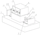
Fig. 1 is a schematic structural diagram of a wear-resistant gear box according to the present invention.
Fig. 2 is a front view of a wear-resistant gear box according to the present invention.
Fig. 3 is a side view of a wear resistant gear box of the present invention.
Fig. 4 is a cross-sectional view of the a-a line structure of fig. 3 according to the present invention.
Fig. 5 is a partial enlarged view of the position B of fig. 4 according to the present invention.
1-base, 2-damping component, 21-fixing plate, 22-sliding rail, 23-supporting rod, 24-cylinder, 25-spring, 26-plug block, 27-supporting rod, 28-supporting plate, 29-damping pad, 3-base, 4-gear box body, 5-positioning ring, 6-positioning component, 61-positioning plate, 62-screw, 63-nut, 64-clamping block, 65-mounting hole, 66-fixing rubber pad, 7-groove, 8-mounting groove, 9-clamping plate, 10-rotating upright post, 101-rotating groove and 102-ball.
Detailed Description
Reference will now be made in detail to embodiments of the present invention, examples of which are illustrated in the accompanying drawings.
Referring to fig. 1 to 5, the present invention provides a wear-resistant gear box, which includes a base 1, a shock absorbing assembly 2, a base 3, a gear box body 4, a positioning ring 5 and a positioning assembly 6, wherein the base 3 is movably connected to the base 1 and located above the base 1, two sides of the base 3 are provided with grooves 7, the number of the shock absorbing assembly 2 is two, each group of the shock absorbing assembly 2 is respectively fixedly connected to the base 1 and respectively located at the grooves 7, the gear box body 4 is fixedly connected to the base 3 and located above the base 3, a side of the gear box body 4 is provided with a mounting groove 8, the positioning ring 5 is movably connected to the gear box body 4 and located at the mounting groove 8, the number of the positioning assembly 6 is two, each group of the positioning assembly 6 is respectively movably connected to the positioning ring 5, and are positioned at the two side edges of the positioning ring 5;
every group damper assembly 2 includes fixed plate 21, slide rail 22, bracing piece 23, cylinder body 24, spring 25, chock block 26 and supports and holds pole 27, fixed plate 21 with base 1 fixed connection, and be located the top of base 1, slide rail 22 with fixed plate 21 fixed connection, and be located the side of fixed plate 21, the one end of bracing piece 23 with slide rail 22 swing joint, the other end of bracing piece 23 inserts recess 7, and with recess 7 swing joint, cylinder body 24 with bracing piece 23 fixed connection, and be located the below of bracing piece 23, spring 25 set up in the inside of cylinder body 24, chock block 26 set up in the below of spring 25, support pole 27 set up in the below of chock block 26.
The base 3 is arranged above the base 1, two sets of the damping assemblies 2 are respectively arranged on two side edges of the base 3 and are positioned at the grooves 7 on the two side edges of the base 3, when gears loaded in the gear box body 4 run, vibration is generated, the gear box body 4 vibrates and presses down, the base 3 fixedly connected below the gear box body 4 presses down, the damping assemblies 2 are arranged at the grooves 7 on the two side edges of the base 3, the base 3 drives the supporting rods 23 of each set of the damping assemblies 2 to press down, the cylinder body 24 is fixedly connected below the supporting rods 23, the spring 25 is arranged in the cylinder body 24, the plug block 26 below the spring 25 moves upwards due to the compression of the spring 25 under the action of pressure, and the supporting rod 27 fixedly connected with the plug block 26 moves upwards along with the upward movement of the plug block 26, the bracing piece 23 just along with moving down of cylinder body 24 fixed plate 21 side slide on the slide rail 22, it is supplementary the cylinder body 24, spring 25 has certain effect that resets, just can reset it with it has being connected to reach certain shock attenuation effect, the side of gear box body 4 is provided with mounting groove 8, holding ring 5 set up in 8 departments of mounting groove, holding ring 5 can assist gear box body 4 will the inside gear of gear box body 4 is fixed, and is two sets of locating component 6 set up in holding ring 5's both sides limit can be fixed holding ring 5, simultaneously, supplementary damping component 2 strengthens damping component 2's damping effect, and the difficult part that causes becomes flexible damages the deformation to prolong its life.
Each group of the shock absorbing assembly 2 further comprises a supporting plate 28, and the supporting plate 28 is fixedly connected with the supporting rod 27 and is located below the supporting rod 27.
The supporting plate 28 is disposed below the supporting rod 27, and can assist the supporting rod 27 to increase the supporting area of the supporting rod 27, so as to assist the supporting rod to support, and achieve a better damping effect.
Each group the damper assembly 2 further comprises two damper pads 29, and each damper pad 29 is fixedly connected to the damper pad 29 below the support plate 28.
Every equal fixedly connected with in below of backup pad 28 there is shock pad 29, shock pad 29 can assist backup pad 28 support pole 27 pushes down, with fixed connection when backup pad 28 pushes down, just can assist backup pad 28, thereby strengthen right backup pad 28 carries out the shock attenuation, gear box body 4 just is difficult for producing great vibrations effect.
Each group of the shock absorption assembly 2 further comprises a clamping plate 9, and the clamping plate 9 is fixedly connected with the groove 7 and is positioned on the side edge of the support rod 23.
The joint board 9 set up in the inside of recess 7, and with bracing piece 23 looks adaptation, joint board 9 can assist bracing piece 23 supports base 3 because when gear box body 4 produced vibrations, with it fixed connection base 3 just can pass through bracing piece 23's support, supplementary base 3, thereby alleviate gear box body 4's vibrations effect.
Every group locating component 6 includes locating plate 61, screw rod 62, nut 63 and grip block 64, locating plate 61 with gear box body 4 fixed connection, and be located gear box body 4's side, locating plate 61's side has mounting hole 65, screw rod 62 runs through mounting hole 65, and with grip block 64 fixed connection, nut 63 with screw rod 62 swing joint, and be located locating plate 61's side.
Two sets of locating plate 61 of locating component 6 set up in the side of gear box body 4, the top of locating plate 61 has mounting hole 65, screw rod 62 runs through mounting hole 65, and with grip block 64 fixed connection, nut 63 overlaps and locates screw rod 62's outside rotates nut 63, nut 63 just along with screw rod 62 to locating plate 61 department removes, with screw rod 62 fixed connection grip block 64 just to holding ring 5 department removes, just will holding ring 5 advances line location and fixes, thereby will the inside gear of gear box body 4 fixes, and supplementary it reaches certain shock attenuation effect.
Each set of positioning assembly 6 further includes a fixed rubber pad 66, and the fixed rubber pad 66 is fixedly connected with the clamping block 64 and is located at the side of the clamping block 64.
The fixed rubber pad 66 is disposed on the side of the clamping block 64, and when the clamping block 64 clamps and positions the positioning ring 5, the fixed rubber pad 66 can protect the positioning ring, so as to prolong the service life of the positioning ring.
The wear-resistant gear box further comprises a rotating upright 10, a rotating groove 101 is formed above the base 1, and the rotating upright 10 is movably connected with the rotating groove 101 and is positioned inside the rotating groove 101.
The rotary groove 101 is arranged above the base 1, the rotary upright 10 is arranged inside the rotary groove 101, the rotary upright 10 is assisted by the rotary groove 101, and the rotary upright 10 can rotate inside the rotary groove 101, so that the gear box body 4 can be driven to rotate, and the practicability of the gear box is improved.
The wear-resistant gear box further comprises a plurality of balls 102, the number of the balls 102 is multiple, and the balls 102 are arranged below the base 3.
A plurality of balls 102 are arranged below the base 3, and the balls 102 can assist the base 3 to rotate above the rotating upright post 10 and can enhance the rotating effect thereof, so that the practicability is improved.
While the invention has been described with reference to a preferred embodiment, it will be understood by those skilled in the art that various changes in form and details may be made therein without departing from the spirit and scope of the invention.
Claims (8)
1. A wear-resistant gear box is characterized in that,
the wear-resistant gear box comprises a base, shock absorption assemblies, a base, a gear box body, positioning rings and positioning assemblies, wherein the base is movably connected with the base and is positioned above the base, grooves are formed in two side edges of the base, the number of the shock absorption assemblies is two, each group of shock absorption assemblies is respectively fixedly connected with the base and is respectively positioned at the grooves, the gear box body is fixedly connected with the base and is positioned above the base, an installation groove is formed in the side edge of the gear box body, the positioning rings are movably connected with the gear box body and are positioned at the installation grooves, the number of the positioning assemblies is two, and each group of positioning assemblies is respectively movably connected with the positioning rings and is positioned at two side edges of the positioning rings;
every group damping component includes fixed plate, slide rail, bracing piece, cylinder body, spring, chock block and supports and holds the pole, the fixed plate with base fixed connection, and be located the top of base, the slide rail with fixed plate fixed connection, and be located the side of fixed plate, the one end of bracing piece with slide rail swing joint, the other end of bracing piece inserts the recess, and with recess swing joint, the cylinder body with bracing piece fixed connection, and be located the below of bracing piece, the spring set up in the inside of cylinder body, the chock block set up in the below of spring, support the pole set up in the below of chock block.
2. The wear resistant gearbox of claim 1,
each group of damping assemblies further comprises a supporting plate, and the supporting plate is fixedly connected with the abutting rod and is positioned below the abutting rod.
3. The wear resistant gearbox of claim 2,
every group damper still includes the shock pad, the quantity of shock pad is two, every the equal fixedly connected with in below of backup pad the shock pad.
4. The wear resistant gearbox of claim 1,
each group of shock absorption assembly further comprises a clamping and connecting plate, wherein the clamping and connecting plate is fixedly connected with the groove and is positioned on the side edge of the supporting rod.
5. The wear-resistant gearbox of claim 1,
every group locating component includes locating plate, screw rod, nut and grip block, the locating plate with gear box body fixed connection, and be located the side of gear box body, the side of locating plate has the mounting hole, the screw rod runs through the mounting hole, and with grip block fixed connection, the nut with screw rod swing joint, and be located the side of locating plate.
6. A wear resistant gearbox according to claim 5,
each group of positioning assembly further comprises a fixed rubber pad, and the fixed rubber pad is fixedly connected with the clamping block and is positioned on the side edge of the clamping block.
7. The wear resistant gearbox of claim 1,
the wear-resistant gear box further comprises a rotating upright post, a rotating groove is formed above the base, and the rotating upright post is movably connected with the rotating groove and is positioned inside the rotating groove.
8. The wear-resistant gearbox of claim 1,
the wear-resistant gear box further comprises a plurality of balls, and a plurality of balls are arranged below the base.
Priority Applications (1)
| Application Number | Priority Date | Filing Date | Title |
|---|---|---|---|
| CN202121045806.4U CN216843014U (en) | 2021-05-17 | 2021-05-17 | Wear-resistant gear box |
Applications Claiming Priority (1)
| Application Number | Priority Date | Filing Date | Title |
|---|---|---|---|
| CN202121045806.4U CN216843014U (en) | 2021-05-17 | 2021-05-17 | Wear-resistant gear box |
Publications (1)
| Publication Number | Publication Date |
|---|---|
| CN216843014U true CN216843014U (en) | 2022-06-28 |
Family
ID=82082615
Family Applications (1)
| Application Number | Title | Priority Date | Filing Date |
|---|---|---|---|
| CN202121045806.4U Active CN216843014U (en) | 2021-05-17 | 2021-05-17 | Wear-resistant gear box |
Country Status (1)
| Country | Link |
|---|---|
| CN (1) | CN216843014U (en) |
-
2021
- 2021-05-17 CN CN202121045806.4U patent/CN216843014U/en active Active
Similar Documents
| Publication | Publication Date | Title |
|---|---|---|
| CN206849624U (en) | A kind of shock-proof transformer | |
| CN206881077U (en) | A kind of training place for catching movement locus | |
| CN216843014U (en) | Wear-resistant gear box | |
| CN207753547U (en) | A kind of riding automobile motor shock-damping structure | |
| CN207621258U (en) | Mechanical equipment processing damping | |
| CN217362793U (en) | Electromechanical integrated motor protection device | |
| CN207367125U (en) | A kind of computer motherboard is clamped installation locking device | |
| CN212047255U (en) | Novel side anti-collision frame structure | |
| CN214506238U (en) | High-low voltage switch cabinet with good protection effect | |
| CN214366543U (en) | Aerogenerator convenient to it is fixed | |
| CN210859668U (en) | Mining machinery vibration damping mount | |
| CN104047246A (en) | Middle-section upright connecting structure for hawser guard bar | |
| CN210380483U (en) | Lightweight shock-absorbing support | |
| CN108894279B (en) | Water intake device for pumping underground water | |
| CN216406920U (en) | Power plant steam turbine low pressure cylinder reinforcing apparatus | |
| CN107700575B (en) | Connecting device | |
| CN114719016B (en) | Reverse gear shifting cantilever with good buffering effect | |
| CN217241048U (en) | Thermal shock resistant high density circuit board | |
| CN204921560U (en) | Fixing device between concentrated rail way of transmission and rack | |
| CN210440315U (en) | Telescopic rotary hydraulic cylinder | |
| CN213512693U (en) | A shock attenuation installation frame for generator | |
| CN220956583U (en) | Shock absorber device with convenient mounting and dismounting protection component | |
| CN218317731U (en) | Anti-vibration device of filling machine | |
| CN212393105U (en) | PLC controller for building crane | |
| CN219570724U (en) | Protective device for sliding rope |
Legal Events
| Date | Code | Title | Description |
|---|---|---|---|
| GR01 | Patent grant | ||
| GR01 | Patent grant |