CN216839031U - Tool for splicing steel box girder with inclined column structure - Google Patents
Tool for splicing steel box girder with inclined column structure Download PDFInfo
- Publication number
- CN216839031U CN216839031U CN202220295653.7U CN202220295653U CN216839031U CN 216839031 U CN216839031 U CN 216839031U CN 202220295653 U CN202220295653 U CN 202220295653U CN 216839031 U CN216839031 U CN 216839031U
- Authority
- CN
- China
- Prior art keywords
- tool
- steel box
- transverse connecting
- box girder
- base
- Prior art date
- Legal status (The legal status is an assumption and is not a legal conclusion. Google has not performed a legal analysis and makes no representation as to the accuracy of the status listed.)
- Expired - Fee Related
Links
- 229910000831 Steel Inorganic materials 0.000 title claims abstract description 23
- 239000010959 steel Substances 0.000 title claims abstract description 23
- 230000008093 supporting effect Effects 0.000 claims abstract description 27
- 230000000712 assembly Effects 0.000 claims description 6
- 238000000429 assembly Methods 0.000 claims description 6
- 238000003466 welding Methods 0.000 abstract description 10
- 238000010276 construction Methods 0.000 description 2
- 230000000694 effects Effects 0.000 description 1
- 238000009434 installation Methods 0.000 description 1
- 238000000034 method Methods 0.000 description 1
- 239000000203 mixture Substances 0.000 description 1
- 239000002699 waste material Substances 0.000 description 1
Images

Abstract
The utility model discloses a tool for splicing steel box girders with an oblique column structure, which comprises a base, wherein four support rods are arranged on the base, telescopic components are arranged on the four support rods, walking wheels are arranged on the telescopic components, two main support rods are vertically arranged on the base at intervals, and each main support rod is connected with the support rod through two auxiliary support rods; the main support rod is provided with a plurality of mounting supports, the mounting supports are provided with grooves, the mounting supports are provided with transverse connecting rods, and the transverse connecting rods are provided with two bulges; the transverse connecting rod is provided with a waist-shaped groove, the waist-shaped groove is detachably provided with a positioning stop block, and the transverse connecting rod is also provided with a level bar. The tool can be used for conveniently welding two steel box girders, can adjust the integral supporting height according to the height of the inclined column structure, is convenient to move, and is simple to operate and good in supporting effect.
Description
Technical Field
The utility model relates to a bridge construction technical field, concretely relates to frock is used in concatenation of steel case roof beam with batter post structure.
Background
When the bridge construction, it is usually to weld the steel box girder as a whole and hoist welded steel box girder to the bridge pier stud on and install, when the welding is assembled to double-deck steel box girder structure, through installing cantilever beam and batter post on the steel box girder, use hoisting equipment to hoist two steel box girders when the welding and get up and reuse the support and support the regulation to the steel box girder, the support height that uses at present can not be adjusted, and need many people to assist when adjusting two steel box girder levelness again, waste time and energy, complex operation.
SUMMERY OF THE UTILITY MODEL
The utility model aims at providing a frock is used in steel case roof beam concatenation with batter post structure, this frock can be convenient for to the welding operation of two steel case roof beams, can be convenient for remove according to the holistic support height of altitude mixture control of batter post structure, easy operation, and the support effect is good.
In order to achieve the purpose, the utility model adopts the following technical proposal:
a tool with an oblique column structure for splicing steel box beams comprises a base, wherein four supporting rods are arranged on the base, telescopic assemblies are arranged on the four supporting rods, walking wheels are arranged on the telescopic assemblies, two main supporting rods are vertically arranged on the base at intervals, and each main supporting rod is connected with the supporting rod through two auxiliary supporting rods; the main support rod is provided with a plurality of mounting supports, the mounting supports are provided with grooves, the mounting supports are provided with transverse connecting rods, the transverse connecting rods are provided with two bulges, and when the transverse connecting rods are arranged on the mounting supports, the bulges are positioned in the grooves; the transverse connecting rod is provided with a waist-shaped groove, the waist-shaped groove is detachably provided with a positioning stop block, and the transverse connecting rod is also provided with a level bar.
Preferably, the telescopic assembly is a jack.
Preferably, the walking wheel is the universal wheel, still is equipped with the brake subassembly on the walking wheel.
Preferably, an oblique auxiliary connecting rod is further arranged between the main supporting rod and the base.
Preferably, the groove is rectangular, and the protrusion is rectangular corresponding to the groove.
Preferably, the height of the protrusion is not greater than the depth of the groove.
The utility model discloses in, but the height between the relative base of walking wheel can be adjusted to the telescopic component of setting, and the place of actual welding operation is unevenness's road surface usually, highly makes the base can realize comparatively more horizontality through adjusting telescopic component for the device can be applicable to more abominable road surface operating mode, reduces later stage concatenation in-process level adjustment's step, improves the work efficiency of concatenation operation. The walking wheel of setting is convenient for the device's removal, reduces the artifical working strength who moves, and the brake subassembly that sets up can be with walking wheel fast fixed, improves the device during operation stability. The stability and the joint strength of main tributary vaulting pole can be improved to the auxiliary stay pole and the supplementary connecting rod of slant that set up. The groove and the protruding structure which are arranged can be used for quickly and fixedly installing the transverse connecting rod on the mounting support, and the transverse connecting rod is fixed on the mounting support by using the weight of the steel box girder, so that the transverse connecting rod is convenient to install and disassemble. The levelness of the horizontal connecting rod after being installed can be displayed by the set level ruler, so that the horizontal connecting rod is convenient for an operator to observe and adjust.
Drawings
FIG. 1 is a schematic view of the overall structure of the present invention;
FIG. 2 is a schematic view of a partial structure of the present invention;
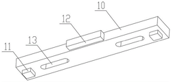
in the figure: 1. a base; 2. a strut; 3. a retractable assembly; 4. a traveling wheel; 5. a main support bar; 6. an auxiliary support bar; 7. an oblique auxiliary connecting rod; 8. mounting a support; 9. a groove; 10. a transverse connecting rod; 11. a protrusion; 12. a level bar; 13. a waist-shaped groove; 14. positioning a stop block; 15. a brake component.
Detailed Description
The present invention will be further explained with reference to the accompanying drawings:
the tool for splicing the steel box girder with the inclined column structure comprises a base 1, wherein four support rods 2 are fixedly connected to the base 1 through welding, and the four support rods 2 and the base 1 form a rectangular installation frame. Telescopic assemblies 3 are vertically and fixedly arranged on the bottom sides of the end parts of the four supporting rods 1 through fasteners, the telescopic assemblies 3 are jacks in one embodiment, and the telescopic assemblies 3 can also be hydraulic cylinders or electric push rods in another embodiment. The telescopic assembly 3 is fixedly provided with a travelling wheel 4 through a fastener, the travelling wheel 4 is a universal wheel in a preferred embodiment, and a brake assembly 15 is further arranged on the travelling wheel 4. Two main supporting rods 5 are vertically arranged on the top surface of the base 1 at intervals, in a more preferable embodiment, the two main supporting rods 5 are symmetrically arranged at two ends of the base 1, the main supporting rods 5 are fixedly connected with the base 1 by welding, each main supporting rod 5 is connected with the supporting rod 2 by two auxiliary supporting rods 6, and the auxiliary supporting rods 6 are fixedly connected with the supporting rods 2 and the main supporting rods 5 by welding. In a further preferred embodiment, an oblique auxiliary connecting rod 7 is fixedly connected between the main supporting rod 5 and the base 1 by welding.
A plurality of mounting supports 8 are fixedly mounted on the inner side of the main support rod 5 in a vertical direction through welding, in one embodiment, the number of the mounting supports 8 is three, four or five, in one embodiment, the number of the mounting supports 8 is five, the five mounting supports 8 are vertically arranged at equal intervals, a groove 9 is formed in the top of each mounting support 8, a transverse connecting rod 10 is mounted on two opposite mounting supports 8, two protrusions 11 are symmetrically arranged at the bottoms of two ends of each transverse connecting rod 10, when the transverse connecting rods 10 are mounted on the mounting supports 8, the protrusions 11 are located in the grooves 9, in a preferred embodiment, the grooves 9 are rectangular, the protrusions 11 are rectangular corresponding to the grooves 9, and the height of the protrusions 11 is not greater than the depth of the grooves 9. In another preferred embodiment the recesses 9 and the protrusions 11 may also be of a cylindrical or truncated cone shape with adapted dimensions. A level 12 is fixedly mounted on the transverse connecting rod 10 by means of fasteners. A waist-shaped groove 13 is further arranged on the top of the transverse connecting rod 10, in a specific embodiment, two waist-shaped grooves 13 are arranged, two waist-shaped grooves 13 are symmetrically arranged on the transverse connecting rod 10, the waist-shaped grooves 13 penetrate through two end faces of the transverse connecting rod 10, a positioning stop block 14 is detachably mounted on the top face of the transverse connecting rod 10 through bolts, the mounting position of the positioning stop block 14 can be adjusted through the waist-shaped grooves 13, and in an embodiment, the positioning stop block 14 is L-shaped.
The above embodiments are only a few descriptions of the concept and implementation of the present invention, and are not intended to limit the scope of the present invention.
Claims (6)
1. The utility model provides a frock is used in concatenation of steel box girder with batter post structure, includes base (1), its characterized in that: the base (1) is provided with four supporting rods (2), the four supporting rods (2) are respectively provided with a telescopic component (3), the telescopic components (3) are provided with traveling wheels (4), the base (1) is vertically provided with two main supporting rods (5) at intervals, and each main supporting rod (5) is connected with the supporting rod (2) through two auxiliary supporting rods (6); the main support rod (5) is provided with a plurality of mounting supports (8), the mounting supports (8) are provided with grooves (9), the mounting supports (8) are provided with transverse connecting rods (10), the transverse connecting rods (10) are provided with two bulges (11), and when the transverse connecting rods (10) are arranged on the mounting supports (8), the bulges (11) are positioned in the grooves (9); a waist-shaped groove (13) is arranged on the transverse connecting rod (10), a positioning stop block (14) is detachably arranged on the waist-shaped groove (13), and a level ruler (12) is also arranged on the transverse connecting rod (10).
2. The tool with the batter post structure for splicing the steel box girder according to claim 1, wherein the tool comprises: the telescopic component (3) is a jack.
3. The tool with the batter post structure for splicing the steel box girder according to claim 1, wherein the tool comprises: the walking wheels (4) are universal wheels, and brake assemblies (15) are further arranged on the walking wheels (4).
4. The tool with the inclined column structure for splicing the steel box girder according to claim 1, and is characterized in that: an oblique auxiliary connecting rod (7) is further arranged between the main supporting rod (5) and the base (1).
5. The tool with the batter post structure for splicing the steel box girder according to claim 1, wherein the tool comprises: the groove (9) is rectangular, and the protrusion (11) is rectangular and is matched with the groove (9).
6. The tool for splicing the steel box girder with the inclined column structure according to claim 1 or 5, wherein the tool comprises: the height of the protrusion (11) is not more than the depth of the groove (9).
Priority Applications (1)
| Application Number | Priority Date | Filing Date | Title |
|---|---|---|---|
| CN202220295653.7U CN216839031U (en) | 2022-02-15 | 2022-02-15 | Tool for splicing steel box girder with inclined column structure |
Applications Claiming Priority (1)
| Application Number | Priority Date | Filing Date | Title |
|---|---|---|---|
| CN202220295653.7U CN216839031U (en) | 2022-02-15 | 2022-02-15 | Tool for splicing steel box girder with inclined column structure |
Publications (1)
| Publication Number | Publication Date |
|---|---|
| CN216839031U true CN216839031U (en) | 2022-06-28 |
Family
ID=82088450
Family Applications (1)
| Application Number | Title | Priority Date | Filing Date |
|---|---|---|---|
| CN202220295653.7U Expired - Fee Related CN216839031U (en) | 2022-02-15 | 2022-02-15 | Tool for splicing steel box girder with inclined column structure |
Country Status (1)
| Country | Link |
|---|---|
| CN (1) | CN216839031U (en) |
Cited By (1)
| Publication number | Priority date | Publication date | Assignee | Title |
|---|---|---|---|---|
| CN115234762A (en) * | 2022-06-29 | 2022-10-25 | 中国建筑一局(集团)有限公司 | Detachable supporting device for mounting of material distributing machine and using method |
-
2022
- 2022-02-15 CN CN202220295653.7U patent/CN216839031U/en not_active Expired - Fee Related
Cited By (1)
| Publication number | Priority date | Publication date | Assignee | Title |
|---|---|---|---|---|
| CN115234762A (en) * | 2022-06-29 | 2022-10-25 | 中国建筑一局(集团)有限公司 | Detachable supporting device for mounting of material distributing machine and using method |
Similar Documents
| Publication | Publication Date | Title |
|---|---|---|
| CN216839031U (en) | Tool for splicing steel box girder with inclined column structure | |
| CN111877345B (en) | Steel pipe pile positioning device for steel trestle construction in water area and construction method | |
| JP2918475B2 (en) | Pier construction method, pier dismantling method and lift-up / rotation device | |
| CN215052151U (en) | Temporary supporting device for bridge construction | |
| CN113216007A (en) | Pier construction equipment and pier construction method | |
| CN209873592U (en) | Lifting type movable auxiliary tool for installing variable-section cantilever on steel box girder | |
| CN216889750U (en) | Detachable movable portal frame for improving hoisting operation safety | |
| CN114876209A (en) | Steel reinforced beam sectional construction method for limited hoisting | |
| CN212224677U (en) | Temporary fixing adjusting system for drop position of section steel beam | |
| CN212245935U (en) | High mound girder steel top pushes away equipment hoist device | |
| CN212224669U (en) | Super large box steel column installation system | |
| CN107237515A (en) | The support meanss and its application method of circular steel truss structure | |
| CN111749144A (en) | Movable cast-in-place beam side mold device and using method thereof | |
| CN218175619U (en) | Installation device for rotating steel structure bridge support | |
| CN214459664U (en) | Floor-free pier column bent cap template dismounting device | |
| CN218712236U (en) | External mold device applied to continuous beam construction | |
| CN214658680U (en) | Stiffness type steel reinforced concrete beam lower hanging operation platform | |
| CN211922307U (en) | Pier stud guiding and limiting device | |
| CN220433647U (en) | Guide frame for pile sinking of steel pipe pile | |
| CN211230501U (en) | Combined frame body device of non-portal lining trolley | |
| CN219118807U (en) | Construction structure is built to slope steel column | |
| CN218581144U (en) | Large steel pipe support parallel-connection movable construction platform | |
| CN213837426U (en) | Steel stair that is used for workman to go up and down operation before prefabricated stair do not install | |
| CN212801257U (en) | Movable cast-in-situ beam side mold device | |
| CN212452315U (en) | Assembly module and modular construction platform |
Legal Events
| Date | Code | Title | Description |
|---|---|---|---|
| GR01 | Patent grant | ||
| GR01 | Patent grant | ||
| CF01 | Termination of patent right due to non-payment of annual fee |
Granted publication date: 20220628 |
|
| CF01 | Termination of patent right due to non-payment of annual fee |