CN216803934U - Mixing mechanism convenient to concrete carries out rapid mixing - Google Patents
Mixing mechanism convenient to concrete carries out rapid mixing Download PDFInfo
- Publication number
- CN216803934U CN216803934U CN202123061290.5U CN202123061290U CN216803934U CN 216803934 U CN216803934 U CN 216803934U CN 202123061290 U CN202123061290 U CN 202123061290U CN 216803934 U CN216803934 U CN 216803934U
- Authority
- CN
- China
- Prior art keywords
- stirring
- driving
- mixing
- shaft
- bevel gear
- Prior art date
- Legal status (The legal status is an assumption and is not a legal conclusion. Google has not performed a legal analysis and makes no representation as to the accuracy of the status listed.)
- Active
Links
Images


Abstract
The utility model belongs to the technical field of construction and construction equipment, and particularly relates to a mixing mechanism convenient for quickly stirring concrete, which comprises a stirring barrel and a billowing type stirring mechanism arranged on the stirring barrel, wherein the stirring barrel comprises an inner barrel and an outer barrel, and the billowing type stirring mechanism comprises a material billowing mechanism for driving materials to billow and a stirring mechanism for stirring the materials; the stirring mechanism comprises a plurality of groups of transverse stirring mechanisms distributed in the inner barrel in parallel, each transverse stirring mechanism comprises a plurality of stirring assemblies which are uniformly distributed in the inner barrel in an annular shape, and the stirring mechanism also comprises a synchronous driving mechanism used for driving the driving main shaft and all the stirring assemblies to synchronously rotate.
Description
Technical Field
The utility model belongs to the technical field of construction and construction equipment, and particularly relates to a mixing mechanism convenient for rapid stirring of concrete.
Background
Concrete is a common building material and is formed by mixing sand, a cementing material and slurry, and the concrete needs to be stirred by a stirring device so as to uniformly mix all components in the concrete. Chinese patent "a concrete mixer" with publication number CN204748935U discloses a concrete mixer, including the agitator, the central point of agitator puts and is equipped with the (mixing) shaft, and the top of (mixing) shaft is equipped with the striker plate, and the bottom of agitator is equipped with the motor, and the upper portion of (mixing) shaft is equipped with one-level stirring leaf, and the middle part of (mixing) shaft is equipped with second grade stirring leaf, and the lower part of agitator sets up tertiary stirring leaf.
However, the concrete mixer described above has the following disadvantages: the motor drive (mixing) shaft rotates, and the (mixing) shaft rotates and drives one-level stirring leaf, second grade stirring leaf, tertiary stirring leaf and rotates, stirs the mechanical force that only relies on the stirring leaf to the stirring of concrete, and the concrete atress that is close to the stirring leaf is great stirs evenly easily, and the concrete atress of keeping away from the stirring leaf is less, is difficult to by the stirring.
SUMMERY OF THE UTILITY MODEL
The utility model aims to provide a mixing mechanism which is convenient for rapid mixing of concrete.
In order to achieve the purpose, the utility model adopts the following technical scheme:
the stirring barrel comprises an inner barrel and an outer barrel which are coaxially distributed, and the stirring mechanism comprises a material stirring mechanism for driving materials to stir and a stirring mechanism for stirring the materials;
the material surge mechanism comprises a driving main shaft and surge components which are arranged on the driving main shaft in parallel at equal intervals, the driving main shaft is vertically and rotatably arranged in the inner barrel, and the lower end of the driving main shaft extends to the lower part of the inner barrel;
the stirring mechanism comprises a plurality of groups of transverse stirring mechanisms which are distributed in the inner barrel in parallel, each transverse stirring mechanism comprises a plurality of stirring components which are uniformly distributed in the inner barrel in a ring shape, the end parts of the stirring components are rotationally connected with the inner wall of the inner barrel, the end parts of the stirring components extend to the outside of the inner barrel, and the stirring components vertically point to the central axis of the inner barrel;
the stirring device is characterized by further comprising a synchronous driving mechanism for driving the driving main shaft and all the stirring assemblies to synchronously rotate, wherein the power output end of the synchronous driving mechanism is respectively connected with the power input ends of the driving main shaft and the stirring assemblies.
Preferably, each piping component comprises a positioning block and piping plates which are annularly and uniformly distributed on the outer wall of the positioning block, the positioning block is detachably mounted on the driving spindle through a fastener, and the piping plates are strip-shaped plates which are obliquely distributed on the outer wall of the positioning block;
the surge plates and the stirring assemblies are distributed in a staggered mode.
Preferably, the synchronous driving mechanism comprises a transverse synchronous driving component, a longitudinal synchronous transmission component and a synchronous transmission component, the stirring components positioned in the same column correspond to one longitudinal synchronous transmission component, the power input end of each stirring component is connected with the power output end of each longitudinal synchronous transmission component, and the longitudinal synchronous transmission components are arranged on the outer wall of the inner barrel;
the synchronous transmission assembly comprises an outer gear ring and straight gears which correspond to the longitudinal synchronous transmission assembly one by one, the straight gears are arranged on the longitudinal synchronous transmission assembly, the outer gear ring is arranged on the outer wall of the inner barrel through a rotating bearing, and all the straight gears are meshed with the outer gear ring;
the horizontal synchronous driving component is arranged below the inner barrel, and the driving end of the horizontal synchronous driving component is respectively connected with the driving main shaft and the end part of one of the vertical synchronous transmission components;
when one of the longitudinal synchronous transmission assemblies rotates, the rest longitudinal synchronous transmission assemblies rotate simultaneously under the action of the straight gear and the outer gear ring.
Preferably, the transverse synchronous driving assembly comprises a driving motor, a transverse driving shaft, a first reversing transmission assembly and a second reversing transmission assembly, the transverse driving shaft is horizontally and rotatably mounted at the lower end of the outer barrel, the driving motor is mounted on the outer wall of the outer barrel, and the driving end of the driving motor is connected with the end part of the transverse driving shaft;
the reversing transmission assembly I comprises a bevel gear I and a bevel gear II which are meshed with each other, the bevel gear I is arranged on the transverse driving shaft, and the bevel gear II is arranged at the end part of one longitudinal synchronous transmission assembly;
the reversing transmission assembly II comprises a bevel gear III and a bevel gear IV which are meshed with each other, the bevel gear III is installed on the transverse driving shaft, and the bevel gear IV is installed at the end part of the driving main shaft.
Preferably, each longitudinal synchronous transmission assembly comprises a transmission shaft and third reversing transmission assemblies which are distributed in parallel at equal intervals, and the third reversing transmission assemblies correspond to the stirring assemblies in the same column one by one;
the transmission shaft is vertically and rotatably arranged on the outer wall of the inner barrel, and the bevel gear II is arranged at the end part of one transmission shaft;
and one end of each reversing transmission assembly is connected with the transmission shaft, and the other end of each reversing transmission assembly is connected with the end part of the corresponding stirring assembly.
Preferably, each reversing transmission assembly III comprises a bevel gear five and a bevel gear six which are meshed with each other, the bevel gear five is installed on the transmission shaft, and the bevel gear six is installed at the end part of the stirring assembly.
Preferably, the stirring assembly comprises a stirring shaft and a stirring rod arranged on the stirring shaft, the stirring shaft is horizontally and rotatably arranged on the side wall of the inner barrel, and the bevel gear six is arranged at the end part of the stirring shaft.
Has the advantages that: when the automatic mixing machine is used, materials to be mixed and stirred are poured into the inner barrel, the driving motor is started, the driving motor drives the transverse driving shaft to rotate, the transverse driving shaft drives one of the transmission shafts to rotate through the reversing transmission assembly when rotating, and the reversing transmission assembly II drives the driving main shaft to rotate;
the driving main shaft drives the billowing plate to synchronously rotate through the positioning block when rotating, and the billowing plate can drive materials to billow when rotating; the transmission shaft is when rotating, through straight-teeth gear and outer ring gear for all straight-teeth gears drive the transmission shaft and all are in the pivoted state simultaneously, and stir on the horizontal direction through three drive stirring subassemblies of switching-over transmission subassembly, and the stirring subassembly is when the stirring, and the cooperation is turned over and is shoved the board and turn over the material and gush, makes the irregular motion aggravation of material, thereby has improved the efficiency of mixing stirring, has improved the stirring efficiency and the stirring quality of material.
The utility model has simple structure, and can intensify the irregular motion of the materials by synchronously stirring and turning the materials, improve the mixing efficiency and mixing quality of the materials and ensure the quality of the concrete during production.
Drawings
In order to more clearly illustrate the technical solutions of the embodiments of the present invention, the drawings in the embodiments of the present invention are briefly described below.
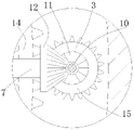
FIG. 1 is a schematic structural view of the present invention;
FIG. 2 is an enlarged view taken at A in FIG. 1;
FIG. 3 is an enlarged view at B of FIG. 1;
FIG. 4 is a schematic view of a synchronous drive mechanism;
FIG. 5 is a schematic view of the operation of the kick plate when the drive spindle is rotated;
1-inner barrel, 2-outer barrel, 3-driving spindle, 4-positioning block, 5-fastening piece, 6-billowing plate, 7-stirring shaft, 8-stirring rod, 9-driving motor, 10-transmission shaft, 11-bevel gear five, 12-bevel gear six, 13-rotating bearing, 14-outer gear ring, 15-straight gear, 16-transverse driving shaft, 17-bevel gear one, 18-bevel gear two, 19-bevel gear three and 20-bevel gear four.
Detailed Description
The technical scheme of the utility model is further explained by the specific implementation mode in combination with the attached drawings.
Wherein the showings are for the purpose of illustration only and are shown by way of illustration only and not in actual form, and are not to be construed as limiting the present patent; to better illustrate the embodiments of the present invention, some components of the drawings may be omitted, enlarged or reduced, and do not represent the size of an actual product.
Referring to fig. 1 to 5, the mixing mechanism convenient for rapid mixing of concrete includes a mixing tank and a stirring mechanism disposed on the mixing tank, the mixing tank includes an inner tank 1 and an outer tank 2 which are coaxially disposed, the stirring mechanism includes a material stirring mechanism for driving a material to stir and a stirring mechanism for stirring the material;
the material surge mechanism comprises a driving main shaft 3 and surge components which are arranged on the driving main shaft 3 in parallel at equal intervals, the driving main shaft 3 is vertically and rotatably arranged in the inner barrel 1, and the lower end of the driving main shaft 3 extends to the lower part of the inner barrel 1;
the stirring mechanism comprises a plurality of groups of transverse stirring mechanisms which are distributed in the inner barrel 1 in parallel, each transverse stirring mechanism comprises a plurality of stirring components which are uniformly distributed in the inner barrel 1 in a ring shape, the end parts of the stirring components are rotationally connected with the inner wall of the inner barrel 1 and extend to the outside of the inner barrel 1, and the stirring components vertically point to the central axis of the inner barrel 1;
the stirring device is characterized by further comprising a synchronous driving mechanism for driving the driving main shaft 3 and all the stirring assemblies to synchronously rotate, wherein the power output end of the synchronous driving mechanism is respectively connected with the driving main shaft 3 and the power input ends of the stirring assemblies.
In this embodiment, each of the spewing assemblies includes a positioning block 4 and a spewing plate 6 annularly and uniformly distributed on the outer wall of the positioning block 4, the positioning block 4 is detachably mounted on the driving spindle 3 through a fastener 5, and the spewing plate 6 is a strip-shaped plate obliquely distributed on the outer wall of the positioning block 4;
the billowing plates 6 and the stirring components are distributed in a staggered mode.
In this embodiment, the synchronous driving mechanism includes a horizontal synchronous driving component, a longitudinal synchronous transmission component and a synchronous transmission component, the stirring components located in the same column correspond to one longitudinal synchronous transmission component, the power input end of the stirring component is connected with the power output end of the longitudinal synchronous transmission component, and the plurality of longitudinal synchronous transmission components are arranged on the outer wall of the inner barrel 1;
the synchronous transmission assembly comprises an outer gear ring 14 and straight gears 15 which are in one-to-one correspondence with the longitudinal synchronous transmission assembly, the straight gears 15 are installed on the longitudinal synchronous transmission assembly, the outer gear ring 14 is installed on the outer wall of the inner barrel 1 through a rotating bearing 13, and all the straight gears 15 are meshed with the outer gear ring 14;
the horizontal synchronous driving component is arranged below the inner barrel 1, and the driving end of the horizontal synchronous driving component is respectively connected with the driving main shaft 3 and the end part of one of the vertical synchronous transmission components;
when one of the longitudinal synchronous transmission assemblies rotates, the rest longitudinal synchronous transmission assemblies rotate simultaneously under the action of the straight gear 15 and the external gear ring 14.
In this embodiment, the horizontal synchronous driving assembly includes a driving motor 9, a horizontal driving shaft 16, a first reversing transmission assembly and a second reversing transmission assembly, the horizontal driving shaft 16 is horizontally and rotatably installed at the lower end of the outer tub 2, the driving motor 9 is installed on the outer wall of the outer tub 2, and the driving end of the driving motor 9 is connected with the end of the horizontal driving shaft 16;
the reversing transmission assembly I comprises a first bevel gear 17 and a second bevel gear 18 which are meshed with each other, the first bevel gear 17 is installed on the transverse driving shaft 16, and the second bevel gear 18 is installed at the end of one of the longitudinal synchronous transmission assemblies;
the second reversing transmission assembly comprises a third bevel gear 19 and a fourth bevel gear 20 which are meshed with each other, the third bevel gear 19 is installed on the transverse driving shaft 16, and the fourth bevel gear 20 is installed at the end part of the driving spindle 3.
In this embodiment, each of the longitudinal synchronous transmission assemblies includes a transmission shaft 10 and third reversing transmission assemblies which are distributed in parallel at equal intervals, and the third reversing transmission assemblies correspond to the stirring assemblies in the same column one by one;
the transmission shafts 10 are vertically and rotatably installed on the outer wall of the inner barrel 1, and the bevel gear II 18 is installed at the end of one of the transmission shafts 10;
and one end of each reversing transmission assembly is connected with the transmission shaft 10, and the other end of each reversing transmission assembly is connected with the end part of the corresponding stirring assembly.
In the embodiment, each reversing transmission assembly III comprises a bevel gear five 11 and a bevel gear six 12 which are meshed with each other, the bevel gear five 11 is installed on the transmission shaft 10, and the bevel gear six 12 is installed at the end part of the stirring assembly.
In this embodiment, the stirring assembly includes a stirring shaft 7 and a stirring rod 8 disposed on the stirring shaft 7, the stirring shaft 7 is horizontally rotatably installed on the sidewall of the inner tub 1, and the bevel gear six 12 is installed at the end of the stirring shaft 7.
When the mixing and stirring device is used, materials to be mixed and stirred are poured into the inner barrel 1, the driving motor 9 is started, the driving motor 9 drives the transverse driving shaft 16 to rotate, the transverse driving shaft 16 drives one of the transmission shafts 10 to rotate through the first reversing transmission assembly when rotating, and the driving main shaft 3 is driven to rotate through the second reversing transmission assembly;
the driving main shaft 3 drives the billowing plate 6 to synchronously rotate through the positioning block 4 when rotating, and the billowing plate 6 can drive materials to billow when rotating; transmission shaft 10 is when rotating, through straight-teeth gear 15 and outer ring gear 14 for all straight-teeth gears 15 drive transmission shaft 10 and all are in the pivoted state simultaneously, and stir on the horizontal direction through three drive stirring subassemblies of switching-over transmission subassembly, and the stirring subassembly is when the stirring, and the cooperation is turned over and is shoved the board 6 and is turned over the material, makes the irregular motion aggravation of material, thereby has improved the efficiency of mixing the stirring, has improved the stirring efficiency and the stirring quality of material.
The utility model has simple structure, and can intensify the irregular motion of the materials by synchronously stirring and turning the materials, improve the mixing efficiency and mixing quality of the materials and ensure the quality of the concrete during production.
The above-mentioned embodiments are only used for illustrating the technical solutions of the present invention, and not for limiting the same; although the present invention has been described in detail with reference to the foregoing embodiments, it will be understood by those of ordinary skill in the art that: the technical solutions described in the foregoing embodiments may still be modified, or some technical features may be equivalently replaced; and such modifications or substitutions do not depart from the spirit and scope of the corresponding technical solutions of the embodiments of the present invention.
Claims (7)
1. A mixing mechanism convenient for rapid stirring of concrete comprises a stirring barrel and a stirring mechanism arranged on the stirring barrel, and is characterized in that the stirring barrel comprises an inner barrel (1) and an outer barrel (2) which are coaxially distributed, and the stirring mechanism comprises a material stirring mechanism for driving materials to stir and a stirring mechanism for stirring the materials;
the material surge mechanism comprises a driving main shaft (3) and surge components which are arranged on the driving main shaft (3) in parallel at equal intervals, the driving main shaft (3) is vertically and rotatably arranged in the inner barrel (1), and the lower end of the driving main shaft (3) extends to the lower part of the inner barrel (1);
the stirring mechanism comprises a plurality of groups of transverse stirring mechanisms which are distributed in the inner barrel (1) in parallel, each transverse stirring mechanism comprises a plurality of stirring components which are uniformly distributed in the inner barrel (1) in an annular mode, the end parts of the stirring components are rotatably connected with the inner wall of the inner barrel (1), the end parts of the stirring components extend to the outside of the inner barrel (1), and the stirring components vertically point to the central axis of the inner barrel (1);
the stirring device is characterized by further comprising a synchronous driving mechanism for driving the driving main shaft (3) and all the stirring assemblies to synchronously rotate, wherein the power output end of the synchronous driving mechanism is respectively connected with the driving main shaft (3) and the power input end of the stirring assemblies.
2. The mixing mechanism for facilitating the rapid mixing of concrete according to claim 1, wherein each of the billowing assemblies comprises a positioning block (4) and a billowing plate (6) annularly and uniformly distributed on the outer wall of the positioning block (4), the positioning block (4) is detachably mounted on the driving spindle (3) through a fastener (5), and the billowing plates (6) are strip-shaped plates obliquely distributed on the outer wall of the positioning block (4);
the billowing plates (6) and the stirring components are distributed in a staggered mode.
3. The mixing mechanism for facilitating the rapid mixing of concrete according to claim 1, wherein the synchronous driving mechanism comprises a horizontal synchronous driving component, a vertical synchronous transmission component and a synchronous transmission component, the mixing components in the same column correspond to one vertical synchronous transmission component, the power input end of the mixing components is connected with the power output end of the vertical synchronous transmission component, and a plurality of vertical synchronous transmission components are arranged on the outer wall of the inner barrel (1);
the synchronous transmission assembly comprises an outer gear ring (14) and straight gears (15) which correspond to the longitudinal synchronous transmission assembly one by one, the straight gears (15) are installed on the longitudinal synchronous transmission assembly, the outer gear ring (14) is installed on the outer wall of the inner barrel (1) through a rotating bearing (13), and all the straight gears (15) are meshed with the outer gear ring (14);
the horizontal synchronous driving component is arranged below the inner barrel (1), and the driving end of the horizontal synchronous driving component is respectively connected with the driving main shaft (3) and the end part of one of the vertical synchronous transmission components;
when one of the longitudinal synchronous transmission assemblies rotates, the rest longitudinal synchronous transmission assemblies rotate simultaneously under the action of the straight gear (15) and the external gear ring (14).
4. The mixing mechanism for facilitating the rapid mixing of concrete according to claim 3, wherein the transverse synchronous driving assembly comprises a driving motor (9), a transverse driving shaft (16), a first reversing transmission assembly and a second reversing transmission assembly, the transverse driving shaft (16) is horizontally and rotatably installed at the lower end of the outer barrel (2), the driving motor (9) is installed on the outer wall of the outer barrel (2), and the driving end of the driving motor (9) is connected with the end of the transverse driving shaft (16);
the reversing transmission assembly I comprises a bevel gear I (17) and a bevel gear II (18) which are meshed with each other, the bevel gear I (17) is installed on the transverse driving shaft (16), and the bevel gear II (18) is installed at the end of one of the longitudinal synchronous transmission assemblies;
the reversing transmission assembly II comprises a bevel gear III (19) and a bevel gear IV (20) which are meshed with each other, the bevel gear III (19) is installed on the transverse driving shaft (16), and the bevel gear IV (20) is installed at the end part of the driving main shaft (3).
5. The mixing mechanism for facilitating the rapid mixing of concrete according to claim 4, wherein each longitudinal synchronous transmission assembly comprises a transmission shaft (10) and three reversing transmission assemblies which are distributed in parallel at equal intervals, and the three reversing transmission assemblies correspond to the mixing assemblies in the same column one by one;
the transmission shafts (10) are vertically and rotatably arranged on the outer wall of the inner barrel (1), and the bevel gear II (18) is arranged at the end part of one transmission shaft (10);
and one end of each reversing transmission assembly is connected with the transmission shaft (10), and the other end of each reversing transmission assembly is connected with the end part of the corresponding stirring assembly.
6. A mixing mechanism for facilitating rapid mixing of concrete according to claim 5 wherein each reversing drive assembly three comprises a bevel gear five (11) and a bevel gear six (12) which are meshed with each other, the bevel gear five (11) being mounted on the drive shaft (10) and the bevel gear six (12) being mounted at the end of the mixing assembly.
7. The mixing mechanism for facilitating the rapid mixing of concrete according to claim 6, wherein the mixing assembly comprises a mixing shaft (7) and a mixing rod (8) arranged on the mixing shaft (7), the mixing shaft (7) is horizontally and rotatably installed on the side wall of the inner barrel (1), and the bevel gear six (12) is installed at the end of the mixing shaft (7).
Priority Applications (1)
| Application Number | Priority Date | Filing Date | Title |
|---|---|---|---|
| CN202123061290.5U CN216803934U (en) | 2021-12-07 | 2021-12-07 | Mixing mechanism convenient to concrete carries out rapid mixing |
Applications Claiming Priority (1)
| Application Number | Priority Date | Filing Date | Title |
|---|---|---|---|
| CN202123061290.5U CN216803934U (en) | 2021-12-07 | 2021-12-07 | Mixing mechanism convenient to concrete carries out rapid mixing |
Publications (1)
| Publication Number | Publication Date |
|---|---|
| CN216803934U true CN216803934U (en) | 2022-06-24 |
Family
ID=82051451
Family Applications (1)
| Application Number | Title | Priority Date | Filing Date |
|---|---|---|---|
| CN202123061290.5U Active CN216803934U (en) | 2021-12-07 | 2021-12-07 | Mixing mechanism convenient to concrete carries out rapid mixing |
Country Status (1)
| Country | Link |
|---|---|
| CN (1) | CN216803934U (en) |
-
2021
- 2021-12-07 CN CN202123061290.5U patent/CN216803934U/en active Active
Similar Documents
| Publication | Publication Date | Title |
|---|---|---|
| CN209735455U (en) | Production compounding agitating unit for carbon adsorbent | |
| CN110756075A (en) | Food mixer | |
| CN208359079U (en) | A kind of blender for concrete mixing plant | |
| CN216803934U (en) | Mixing mechanism convenient to concrete carries out rapid mixing | |
| CN111450760A (en) | Low moisture content stirring homogenization equipment | |
| WO2020088359A1 (en) | Combined drum-type vertical-shaft mixer having two worm gears and single-worm transmission | |
| CN218138920U (en) | Cement mortar stirrer | |
| CN216329156U (en) | Concrete mixer | |
| CN214925697U (en) | A multistation material mixing device for construction | |
| CN113858428B (en) | Concrete omnibearing stirring device for civil construction and working method thereof | |
| CN211706492U (en) | Gypsum powder mixing stirring equipment | |
| CN210651294U (en) | High-efficient concrete mixing device is used in water conservancy construction | |
| CN207862325U (en) | A kind of persimmon vinegar brewing installation for fermenting | |
| CN202097834U (en) | Coaxial dual-speed agitator | |
| CN220297494U (en) | Mixing arrangement is used in terrace mortar production | |
| CN215094560U (en) | Efficient concrete mixing device | |
| CN203694945U (en) | Full-automatic slurry stirring device | |
| CN220052292U (en) | A concrete mixer for concrete production line | |
| CN220610039U (en) | Stirring barrel | |
| CN219209825U (en) | Stirrer for cattle and sheep feed production | |
| CN212263136U (en) | Low moisture content stirring homogenization equipment | |
| CN220030713U (en) | Concrete stirring main machine | |
| CN214020363U (en) | Agitating unit is used in flocculating agent preparation | |
| CN214773185U (en) | Plastic stirring machine | |
| CN216000937U (en) | Building engineering construction is with mixing agitated vessel |
Legal Events
| Date | Code | Title | Description |
|---|---|---|---|
| GR01 | Patent grant | ||
| GR01 | Patent grant |