CN216803201U - Multifunctional module puller based on barrel type double-layer structure - Google Patents
Multifunctional module puller based on barrel type double-layer structure Download PDFInfo
- Publication number
- CN216803201U CN216803201U CN202122542369.3U CN202122542369U CN216803201U CN 216803201 U CN216803201 U CN 216803201U CN 202122542369 U CN202122542369 U CN 202122542369U CN 216803201 U CN216803201 U CN 216803201U
- Authority
- CN
- China
- Prior art keywords
- plate
- fixedly connected
- vertical plate
- bottom end
- dovetail
- Prior art date
- Legal status (The legal status is an assumption and is not a legal conclusion. Google has not performed a legal analysis and makes no representation as to the accuracy of the status listed.)
- Active
Links
Images


Abstract
The utility model relates to a multifunctional module extractor based on a cylinder type double-layer structure, which comprises a fixed frame, wherein the fixed frame is formed by integrally designing a transverse plate, a pulling plate and a vertical plate, the pulling plate and the vertical plate are respectively arranged on two sides of the bottom end of the transverse plate, the vertical plate is arranged on the inner side of the pulling plate, the top end of the vertical plate is fixedly connected with the bottom of the transverse plate, dovetail grooves are formed in the inner side surface of the vertical plate and the inner side surface of the vertical plate, dovetail plates are arranged in the dovetail grooves, buckles are fixedly connected to the side surfaces of the dovetail plates, the bottom end of the vertical plate is fixedly connected with a pressing plate through screws, a clamping groove is formed in the bottom end of the pressing plate, the bottom end of the vertical plate is fixedly connected with a hook support through screws, and the bottom end of the inner side of the hook support is fixedly connected with a clamping hook through screws. The utility model can reduce the loss rate of the module while pulling up the module, prevent the ammeter from falling off and improve the safety of live working.
Description
Technical Field
The utility model belongs to the technical field of module extractors, and particularly relates to a multifunctional module extractor based on a cylindrical double-layer structure.
Background
At present, because of the continuous development of the technology, the installation rotation frequency of various modules of the field metering device is continuously improved, the module is pulled up, and the safety standard of operation is ensured to be particularly important.
Disclosure of Invention
The utility model aims to overcome the defects of the prior art, and provides a multifunctional module puller based on a cylinder type double-layer structure, which can reduce the loss rate of a module while pulling the module, prevent an ammeter from falling off and improve the safety of live working.
The technical scheme adopted by the utility model is as follows: the multifunctional module puller based on the cylinder type double-layer structure comprises a fixing frame, wherein the fixing frame is formed by integrally designing a transverse plate, a pulling plate and a vertical plate, the pulling plate and the vertical plate are respectively arranged at two sides of the bottom end of the transverse plate, the vertical plate is arranged at the inner side of the pulling plate, the top end of the vertical plate is fixedly connected with the bottom of the transverse plate, dovetail grooves are respectively formed in the inner side surface of the vertical plate and the inner side surface of the vertical plate, a dovetail plate is arranged in each dovetail groove, a buckle is fixedly connected to the side surface of the dovetail plate, a pressing plate is fixedly connected to the bottom end of the vertical plate through screws, a clamping groove is formed in the bottom end of the pressing plate, a hook support is fixedly connected to the bottom end of the vertical plate through screws, a clamping hook is fixedly connected to the inner side end of the hook support through screws, a large handle is fixedly connected to the top end of the transverse plate, a small handle is arranged at the inner side of the large handle, and a limiting block is fixedly connected to the side surface of the small handle, the stopper is located the top of diaphragm, two bottom portions of small handle all run through the diaphragm and respectively fixedly connected with telescoping device, the below of diaphragm is provided with the push rod, telescoping device's bottom and the top fixed connection of push rod.
Preferably, the telescopic device comprises a fixed cylinder, a movable shaft and a spring, the top of the fixed cylinder is fixedly connected with the bottom of the transverse plate, the movable shaft is inserted into the fixed cylinder, the bottom end of the movable shaft is fixedly connected with the top of the push rod, the bottom end of the spring is fixedly connected with the top end of the movable shaft, and the top end of the spring is fixedly connected with the bottom end of the small handle.
Preferably, the depth of the dovetail groove on the inner side of the vertical plate is greater than that of the dovetail groove on the inner side of the vertical plate, the height of the dovetail groove on the inner side of the vertical plate is less than that of the dovetail groove on the inner side of the vertical plate, and the size of the dovetail plate corresponds to that of the dovetail groove.
Preferably, the dovetail plates are fixed in the dovetail grooves through screws, and the buckles on the two dovetail plates are oppositely arranged.
Preferably, the hook support, the clamping hook and the inner side surface of the vertical plate are all parallel and level, and the inner side end of the pressure plate protrudes out of the inner side surface of the vertical plate.
The utility model has the beneficial effects that: according to the utility model, through the arrangement of the pressing plate and the clamping hook, the clamping groove on the pressing plate can be vertically clamped at the edge between the edge of the ammeter and the ammeter module, the clamping hook and the pressing plate are matched to realize the fixation of the ammeter, the clamping hooks on the two dovetail plates are clamped with the notches on the two sides of the module, the pulling plate swings back and forth, the two clamping hooks apply force to the module to drive the module to loosen and partially move out of the module groove, then the large handle is pulled to take out the module, the ammeter is fixed in the process, and only slight swinging is generated when the module is pulled out, the ammeter can be prevented from falling off, the safety of live working is improved, meanwhile, the module can be easily pulled out under the action of the two clamping hooks, and the loss rate of the module is reduced; according to the utility model, through the arrangement of the telescopic device, the small handle and the push rod, the module can be placed at the module groove, the spring drives the movable shaft to further drive the push rod to move by pressing the small handle, so that the module is accurately pushed into the module groove, and the installation efficiency of the module is improved.
Drawings
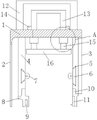
FIG. 1 is a schematic front view of the present invention;
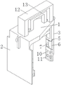
FIG. 2 is a schematic perspective view of the present invention;
FIG. 3 is another perspective view of the present invention;
fig. 4 is a schematic cross-sectional view of the portion a in fig. 1.
In the figure: 1. the device comprises a transverse plate 2, a pulling plate 3, a vertical plate 4, a vertical plate 5, a dovetail groove 6, a dovetail plate 7, a buckle 8, a pressing plate 9, a clamping groove 10, a hook support 11, a clamping hook 12, a large handle 13, a small handle 14, a limiting block 15, a telescopic device 151, a fixed cylinder 152, a movable shaft 153, a spring 16 and a push rod.
Detailed Description
The technical solution in the embodiments of the present invention will be clearly and completely described below with reference to the accompanying drawings in the embodiments of the present invention. All other embodiments, which can be obtained by a person skilled in the art without making any creative effort based on the embodiments of the present invention, belong to the protection scope of the present invention, and are specifically described below with reference to the embodiments.
As shown in fig. 1, 2 and 3, the multifunctional module extractor based on the cylinder type double-layer structure comprises a fixing frame, wherein the fixing frame is formed by integrally designing a transverse plate 1, a pulling plate 2 and a vertical plate 3, the pulling plate 2 and the vertical plate 3 are respectively arranged at two sides of the bottom end of the transverse plate 1, the vertical plate 4 is arranged at the inner side of the pulling plate 2, the top end of the vertical plate 4 is fixedly connected with the bottom of the transverse plate 1, dovetail grooves 5 are respectively arranged on the inner side surface of the vertical plate 4 and the inner side surface of the vertical plate 3, dovetail plates 6 are arranged in the dovetail grooves 5, buckles 7 are fixedly connected with the side surfaces of the dovetail plates 6, the bottom end of the vertical plate 4 is fixedly connected with a pressing plate 8 through screws, clamping grooves 9 are arranged at the bottom end of the pressing plate 8, a hook support 10 is fixedly connected with the bottom end of the vertical plate 3 through screws, and a hook 11 is fixedly connected with the bottom end of the inner side of the hook support 10 through screws, the top fixedly connected with big handle 12 of diaphragm 1, the inboard of big handle 12 is provided with little handle 13, the side fixedly connected with stopper 14 of little handle 13, stopper 14 is located the top of diaphragm 1, two bottom portions of little handle 13 all run through diaphragm 1 and fixedly connected with telescoping device 15 respectively, the below of diaphragm 1 is provided with push rod 16, the bottom of telescoping device 15 and the top fixed connection of push rod 16.
As shown in fig. 4, the telescopic device 15 includes a fixed cylinder 151, a movable shaft 152 and a spring 153, the top of the fixed cylinder 151 is fixedly connected to the bottom of the horizontal plate 1, the movable shaft 152 is inserted into the fixed cylinder 151, the bottom end of the movable shaft 152 is fixedly connected to the top of the push rod 16, the bottom end of the spring 153 is fixedly connected to the top end of the movable shaft 152, the top end of the spring 153 is fixedly connected to the bottom end of the small handle 13, when the small handle 13 is pulled upwards, the push rod 16 is driven to move upwards, a new module is placed in a space reserved under the push rod 16, then the small handle 13 is pressed down, and the new module is pushed into the module slot by the push rod 16.
The depth of the dovetail groove 5 on the inner side of the vertical plate 4 is greater than that of the dovetail groove 5 on the inner side of the vertical plate 3, when the pulling plate 2 is pulled, great force can be applied to the dovetail groove 5 on the inner side of the vertical plate 4, so that the module is driven to move by acting on the module, the height of the dovetail groove 5 on the inner side of the vertical plate 4 is smaller than that of the dovetail groove 5 on the inner side of the vertical plate 3, and the size of the dovetail plate 6 corresponds to that of the dovetail groove 5.
The dovetail plate 6 is fixed in the dovetail groove 5 through screws, so that the dovetail plate 6 and the buckles on the surface of the dovetail plate 6 are convenient to detach and replace, when the screws are detached, the dovetail plate 6 is moved out from the side end of the dovetail groove 5, and the two buckles on the dovetail plate 6 are oppositely arranged.
The inner side surfaces of the hook support 10, the hook 11 and the vertical plate 3 are flush, and the inner side end of the pressing plate 8 protrudes out of the inner side surface of the vertical plate 4, so that the clamping groove 9 can be clamped at the edge of the module groove, and an electric meter element is fixed.
When the electric meter puller is used, the electric meter is fixed by the puller, the clamping groove 9 is clamped into the edge of the module groove, the clamping hook 11 is clamped on the other side, the two clamping hooks 11 and the pressing plate 8 are matched to realize the fixation of the electric meter, the clamping hooks 7 on the two dovetail plates 6 are clamped with the notches on the two sides of the module, the pulling plate 2 swings back and forth, the two clamping hooks 7 apply force to the module to enable the module to be loosened and partially move out of the module groove, then the large handle 12 is pulled to take out the module, when the new module is installed, the new module is correspondingly placed at the module groove, the small handle 13 is pressed, the spring 153 drives the movable shaft 152 to further drive the push rod 16 to press downwards, the module is accurately pushed into the module groove, and the replacement of the new module is realized.
It will be evident to those skilled in the art that the utility model is not limited to the details of the foregoing illustrative embodiments, and that the present invention may be embodied in other specific forms without departing from the spirit or essential attributes thereof. The present embodiments are therefore to be considered in all respects as illustrative and not restrictive, the scope of the utility model being indicated by the appended claims rather than by the foregoing description, and all changes which come within the meaning and range of equivalency of the claims are therefore intended to be embraced therein. Any reference sign in a claim should not be construed as limiting the claim concerned.
Claims (5)
1. Multifunctional module pull-out ware based on cylinder bilayer structure, its characterized in that: the fixing frame is formed by integrally designing a transverse plate, a pulling plate and a vertical plate, the pulling plate and the vertical plate are respectively arranged on two sides of the bottom end of the transverse plate, the vertical plate is arranged on the inner side of the pulling plate, the top end of the vertical plate is fixedly connected with the bottom of the transverse plate, dovetail grooves are formed in the inner side surface of the vertical plate and the inner side surface of the vertical plate, a dovetail plate is arranged in each dovetail groove, buckles are fixedly connected to the side surface of each dovetail plate, a pressing plate is fixedly connected to the bottom end of each vertical plate through screws, a clamping groove is formed in the bottom end of each pressing plate, a hook support is fixedly connected to the bottom end of each vertical plate through screws, a clamping hook is fixedly connected to the inner side bottom end of each hook support through screws, a large handle is fixedly connected to the top end of the transverse plate, a small handle is arranged on the inner side of the large handle, a limiting block is fixedly connected to the side surface of the small handle, and the limiting block is positioned at the top of the transverse plate, two bottom end portions of the small handle penetrate through the transverse plate and are fixedly connected with the telescopic devices respectively, a push rod is arranged below the transverse plate, and the bottom end of the telescopic device is fixedly connected with the top of the push rod.
2. The multi-functional module extractor based on cartridge type double-layer structure of claim 1, wherein: the telescopic device comprises a fixed cylinder, a movable shaft and a spring, the top of the fixed cylinder is fixedly connected with the bottom of the transverse plate, the movable shaft is inserted into the fixed cylinder, the bottom end of the movable shaft is fixedly connected with the top of the push rod, the bottom end of the spring is fixedly connected with the top end of the movable shaft, and the top end of the spring is fixedly connected with the bottom end of the small handle.
3. The multi-functional module extractor based on cartridge type double-layer structure of claim 1, wherein: the depth of the dovetail groove on the inner side of the vertical plate is larger than that of the dovetail groove on the inner side of the vertical plate, the height of the dovetail groove on the inner side of the vertical plate is smaller than that of the dovetail groove on the inner side of the vertical plate, and the size of the dovetail plate corresponds to that of the dovetail groove.
4. The multi-functional module extractor based on cartridge type double-layer structure of claim 1, wherein: the dovetail plates are fixed in the dovetail grooves through screws, and the buckles on the two dovetail plates are arranged oppositely.
5. The multi-functional module extractor based on cartridge type double-layer structure of claim 1, wherein: the inner side surfaces of the hook support, the clamping hook and the vertical plate are all parallel and level, and the inner side end of the pressing plate protrudes out of the inner side surface of the vertical plate.
Priority Applications (1)
| Application Number | Priority Date | Filing Date | Title |
|---|---|---|---|
| CN202122542369.3U CN216803201U (en) | 2021-10-21 | 2021-10-21 | Multifunctional module puller based on barrel type double-layer structure |
Applications Claiming Priority (1)
| Application Number | Priority Date | Filing Date | Title |
|---|---|---|---|
| CN202122542369.3U CN216803201U (en) | 2021-10-21 | 2021-10-21 | Multifunctional module puller based on barrel type double-layer structure |
Publications (1)
| Publication Number | Publication Date |
|---|---|
| CN216803201U true CN216803201U (en) | 2022-06-24 |
Family
ID=82048196
Family Applications (1)
| Application Number | Title | Priority Date | Filing Date |
|---|---|---|---|
| CN202122542369.3U Active CN216803201U (en) | 2021-10-21 | 2021-10-21 | Multifunctional module puller based on barrel type double-layer structure |
Country Status (1)
| Country | Link |
|---|---|
| CN (1) | CN216803201U (en) |
-
2021
- 2021-10-21 CN CN202122542369.3U patent/CN216803201U/en active Active
Similar Documents
| Publication | Publication Date | Title |
|---|---|---|
| CN216803201U (en) | Multifunctional module puller based on barrel type double-layer structure | |
| CN114043401A (en) | Multifunctional module puller based on barrel type double-layer structure | |
| CN210147091U (en) | Edge cutting device with fixing mechanism for lithium battery production | |
| CN212480724U (en) | Building monitor convenient to dismantle | |
| CN212726087U (en) | Novel switch board is used in intelligence manufacturing | |
| CN211875543U (en) | Projecting apparatus for education convenient to installation | |
| CN209981738U (en) | Control device for micro-grid for storage battery SOC adjustment | |
| CN110808224A (en) | Automatic stuck point installation all-in-one machine | |
| CN212723888U (en) | Computer mainboard fixing device for computer | |
| CN212979551U (en) | Ink static electricity removing device based on corrugated board printing | |
| CN206239171U (en) | A kind of inner cover structure and it is provided with the electric cooker of the inner cover structure | |
| CN214177129U (en) | Inverter convenient to install | |
| CN216381718U (en) | Testing device of wind power generation new energy equipment | |
| CN214453343U (en) | Case cover convenient to assemble | |
| CN214366618U (en) | Base convenient to vacuum pump installation usefulness | |
| CN215636357U (en) | Smart city comprehensive safety management remote monitoring device | |
| CN218415438U (en) | Electric power quality monitoring devices convenient to installation | |
| CN206781417U (en) | A kind of Multifunctional painting easel | |
| CN211276307U (en) | Auxiliary discharging device for stamping die | |
| CN213782325U (en) | USB female seat convenient to detach | |
| CN210608133U (en) | Earthing switch device convenient to maintenance and change | |
| CN218837953U (en) | Cutting device is used in processing of portrayal board | |
| CN214394676U (en) | Novel magnetic box of assembled building special connection | |
| CN214103913U (en) | Detachable sofa | |
| CN218441466U (en) | Display module clamping device |
Legal Events
| Date | Code | Title | Description |
|---|---|---|---|
| GR01 | Patent grant | ||
| GR01 | Patent grant |