CN216787879U - Interlayer complex special-shaped aluminum veneer curtain wall construction structure - Google Patents
Interlayer complex special-shaped aluminum veneer curtain wall construction structure Download PDFInfo
- Publication number
- CN216787879U CN216787879U CN202220163671.XU CN202220163671U CN216787879U CN 216787879 U CN216787879 U CN 216787879U CN 202220163671 U CN202220163671 U CN 202220163671U CN 216787879 U CN216787879 U CN 216787879U
- Authority
- CN
- China
- Prior art keywords
- special
- shaped aluminum
- crane
- support
- aluminum veneer
- Prior art date
- Legal status (The legal status is an assumption and is not a legal conclusion. Google has not performed a legal analysis and makes no representation as to the accuracy of the status listed.)
- Active
Links
Images


Landscapes
- Conveying And Assembling Of Building Elements In Situ (AREA)
Abstract
The utility model relates to an interlayer complex special-shaped aluminum veneer curtain wall construction structure, which comprises a crane, a special-shaped aluminum veneer unit movable support and a pre-splicing support; the crane is arranged on a building floor plate of a building; the top of the special-shaped aluminum single plate unit moving support is provided with an electric hoist, the bottom of the special-shaped aluminum single plate unit moving support is provided with a universal pulley, a rigid turnover frame support for fixedly placing special-shaped aluminum single plates is arranged below the special-shaped aluminum single plate unit moving support, the top of the rigid turnover frame support is provided with a plurality of hanging rings, the lower part of the rigid turnover frame support is provided with a movable bolt, a bottom fixed bolt and a sliding groove for the movable bolt to move up and down so as to fix the special-shaped aluminum single plates, the electric hoist is connected with the hanging rings through a steel wire rope, and the rigid turnover frame support is lifted to carry out the transport of the special-shaped aluminum single plates; the pre-assembly support is positioned on the site ground. This application can effectively reduce engineering cost, can realize accurate installation of aluminium veneer, quick transport, is showing and is improving the efficiency of construction.
Description
Technical Field
The utility model relates to the technical field of constructional engineering, in particular to a construction structure of an interlayer complex special-shaped aluminum veneer curtain wall.
Background
With the rapid development of the building industry in China, the decoration requirements of buildings are higher and higher, and curtain wall products are widely applied to a plurality of high-rise buildings. The traditional building curtain wall is installed after being processed and manufactured on site, and the processing of curtain wall components on site is difficult to control the precision, the loss and the construction period, and also difficult to meet the requirements on the aspects of environmental protection and civilized construction. At present, the researches on component transportation, a hoisting system, a pre-assembly system, component installation precision control and the like of an interlayer complex special-shaped aluminum veneer curtain wall have some defects and improved places.
In summary, a construction structure of an interlayer complex special-shaped aluminum veneer curtain wall, which has the advantages of high construction speed, high component installation precision, quick component hoisting and repeated use, is urgently needed for the construction of the interlayer complex special-shaped aluminum veneer curtain wall.
SUMMERY OF THE UTILITY MODEL
The utility model aims to provide an interlayer complex special-shaped aluminum veneer curtain wall construction structure aiming at the problems in the prior art.
In order to realize the purpose of the utility model, the utility model adopts the following technical scheme: the interlayer complex special-shaped aluminum veneer curtain wall construction structure comprises a crane capable of being arranged and disassembled, a special-shaped aluminum veneer unit movable support for transporting the special-shaped aluminum veneers and a pre-splicing support for pre-splicing the special-shaped aluminum veneers;
the crane is arranged on a building floor plate of a building and can be fixed on the building floor plate by means of self gravity;
the top of the special-shaped aluminum single plate unit moving support is provided with an electric hoist, the bottom of the special-shaped aluminum single plate unit moving support is provided with a universal pulley, a rigid turnover frame support for fixedly placing a special-shaped aluminum single plate is arranged below the special-shaped aluminum single plate unit moving support, the top of the rigid turnover frame support is provided with a plurality of hanging rings, the lower part of the rigid turnover frame support is provided with a movable bolt, a bottom fixed bolt and a sliding groove for the movable bolt to move up and down so as to fix the special-shaped aluminum single plate, the electric hoist is connected with the hanging rings through a steel wire rope, and the rigid turnover frame support is hoisted to carry out special-shaped aluminum single plate transportation;
the pre-assembly support is positioned on the site ground and used for pre-assembly inspection of the special-shaped aluminum veneer before the special-shaped aluminum veneer is installed on a building.
The working principle and the beneficial effects are as follows: this application can effectively reduce engineering cost, can realize accurate installation of aluminium veneer, quick transport, is showing and is improving the efficiency of construction.
Furthermore, the special-shaped aluminum single plate unit moving support is also provided with a movable bolt fixing assembly for fixing a movable bolt, each movable bolt fixing assembly comprises two clamp plates and a plurality of fastening bolts, a preformed hole for inserting the movable bolt is formed in the center of each clamp plate, and the clamp plates are used for fixing the movable bolt on the lifting rod of the rigid turnover frame support by inserting the movable bolt and locking the fastening bolts.
Furthermore, the crane comprises a crane stress supporting system, a crane stabilizing system, a steel wire rope arranged on the crane stress supporting system, a jack capable of lifting the crane stress supporting system and the crane stabilizing system and a telescopic universal wheel arranged at the bottom of the crane stress supporting system, wherein a winch connected with the steel wire rope is arranged on the crane stress supporting system, the steel wire rope is used for hoisting the special-shaped aluminum single plate through a pulley and an adjusting pulley, and the crane stabilizing system is used for stabilizing the crane stress supporting system by means of self gravity.
Furthermore, the crane stress supporting system is provided with a suspension arm, two ends of the suspension arm are respectively provided with a pulley and a threaded section, the middle part of the suspension arm is welded with a clamping plate, the suspension arm is inserted into a sleeve on a profile steel cross beam of the crane stress supporting system, an anti-slipping baffle of the crane stress supporting system is fixed with the threaded section on the suspension arm through a bolt, the clamping plate of the suspension arm is in close contact with a first sleeve of the crane stress supporting system, and the suspension arm is fixed on the crane stress supporting system through the clamping plate and the anti-slipping baffle.
Further, the crane stabilizing system comprises a balancing weight for providing gravity, a plurality of connecting lug plates arranged at the bottom of the crane stress supporting system and a plurality of telescopic expanding bottom plates.
Further, piece together the support in advance and include the bottom plate, link firmly H shaped steel stand on this bottom plate, locate this H shaped steel stand side and the channel-section steel that the level set up and can dismantle the keel frame of assembling in advance of being connected with this channel-section steel.
Furtherly, assemble keel frame medial surface in advance and be equipped with and pass through the fixed vertical keel of stainless steel bolt group link with the channel-section steel and be used for supporting to assemble keel frame in advance and prop and horizontal fossil fragments, should strengthen to prop two adjacent horizontal fossil fragments about connecting, the channel-section steel all is connected fixedly with the H shaped steel stand with the horizontal fossil fragments that are located the bottommost through fastening bolt.
Drawings
FIG. 1 is a schematic view of the crane installation of the present invention;
FIG. 2 is a top view of the crane;
FIG. 3 is a schematic view of the boom structure of the crane;
FIG. 4 is a schematic elevation view of a pre-assembled scaffold;
FIG. 5 is a schematic structural diagram of a special-shaped aluminum single plate unit moving bracket;
FIG. 6 is a schematic structural view of a rigid turnaround frame;
FIG. 7 is a schematic structural view of a movable latch fixing assembly;
FIG. 8 is a schematic view of an installation structure of an interlayer complex profiled aluminum veneer curtain wall;
fig. 9 is a schematic structural diagram of an aluminum corner connector.
In the figure, 1, a concrete upright post; 2. a floor panel; 3. a special-shaped aluminum veneer; 4. a wire rope; 5. a pulley; 6. a suspension arm; 7. a sleeve; 8. a section steel upright post; 9. adjusting the pulley; 10. the anti-slip baffle plate; 11. a profile steel stringer; 12. a section steel base; 13. a jack; 14. a winch; 15. a telescopic enlarged base plate; 16. a telescopic universal wheel; 17. connecting the ear plates; 18. pre-burying a pull rod; 19. a balancing weight; 20. a threaded section; 21. a section steel beam; 22. a vertical keel; 23. aluminum corner connectors; 24. a reinforcing support; 25. a stainless steel bolt set; 26. channel steel; 27. pre-assembling a keel frame; 28. fastening a bolt; 29. h-shaped steel upright posts; 30. pre-burying a screw; 31. a base plate; 32. a cushion layer; 33. a support stringer; 34. a stay bar; 35. a boom; 36. a bracket beam; 37. an electric hoist; 38. a bracket upright post; 39. a universal pulley; 40. a rigid turnaround frame support; 41. a hoisting ring; 42. a movable bolt; 43. a bolt is fixed at the bottom; 44. a chute; 45. hoisting the upright rod; 46. clamping a plate; 47. reserving a hole; 48. a splint; 49. fireproof rock wool; 50. a transverse keel; 51. a mechanical pedestal anchor bolt; 52. a keel frame.
Detailed Description
The technical solutions in the embodiments of the present invention will be clearly and completely described below with reference to the drawings in the embodiments of the present invention, and it is obvious that the described embodiments are only a part of the embodiments of the present invention, and not all of the embodiments. All other embodiments that can be derived by one of ordinary skill in the art from the embodiments given herein are intended to be within the scope of the present invention.
It will be understood by those skilled in the art that in the present disclosure, the terms "longitudinal," "lateral," "upper," "lower," "front," "rear," "left," "right," "vertical," "horizontal," "top," "bottom," "inner," "outer," and the like are used in an orientation or positional relationship indicated in the drawings for ease of description and simplicity of description, and do not indicate or imply that the referenced device or element must have a particular orientation, be constructed and operated in a particular orientation, and thus, the above terms should not be construed as limiting the present invention.
In the case of the example 1, the following examples are given,
as shown in fig. 1, 4 and 5, the construction structure of the interlayer complex profiled aluminum veneer curtain wall includes a crane capable of being arranged and disassembled, a profiled aluminum veneer unit movable support for transporting the profiled aluminum veneer 3, and a pre-splicing support for pre-splicing the profiled aluminum veneer 3.
Specifically, as shown in fig. 1-3, the crane includes a crane stress supporting system, a crane stabilizing system and a steel wire rope 4 arranged on the crane stress supporting system, a hoist 14 connected with the steel wire rope 4 is arranged on the crane stress supporting system, the steel wire rope 4 hoists the special-shaped aluminum single plate 3 through a pulley 5 and an adjusting pulley 9, and the crane stabilizing system stabilizes the crane stress supporting system by means of its own gravity;
the crane stress supporting system comprises a steel wire rope 4, a pulley 5, a suspension arm 6, a sleeve 7, a profile steel upright post 8, an adjusting pulley 9, an anti-slip baffle 10, a profile steel longitudinal beam 11, a profile steel base 12, a winch 14, a telescopic expanding bottom plate 15, a telescopic universal wheel 16, a connecting lug plate 17, an embedded pull rod 18, a balancing weight 19, a threaded section 20, a profile steel cross beam 21, a clamping plate 46 and the like, and is processed and manufactured in a factory; the steel base 12, the steel upright 8, the steel cross beam 21, the steel longitudinal beam 11 and the like form a crane stress supporting system; the structural steel base 12 is welded with a connecting lug plate 17, the floor panel 2 is provided with embedded pull rods 18 at intervals, the connecting lug plate 17 and the embedded pull rods 18 are fixed through bolts, the structural steel base 12 is provided with a balancing weight 19, the structural steel base 12 is provided with a telescopic expanding bottom plate 15 and the like to form a crane stabilizing system;
wherein, the crane also comprises a jack 13 which can lift the crane stress supporting system and the crane stabilizing system, and a telescopic universal wheel 16 which is arranged at the bottom of the crane stress supporting system.
The device also comprises movable bolt fixing assemblies for fixing the movable bolts 42, each movable bolt fixing assembly comprises two clamping plates 48 and a plurality of fastening bolts 28, a reserved hole 47 for inserting the movable bolt 42 is formed in the center of each clamping plate 48, and the clamping plates 48 are inserted into the movable bolts 42 and lock the fastening bolts 28 so as to fix the movable bolts 42 on the lifting rods 45 of the rigid turnover frame bracket 40.
The crane stress supporting system is provided with a suspension arm 6, two ends of the suspension arm 6 are respectively provided with a pulley 5 and a threaded section 20, the middle part of the suspension arm 6 is welded with a clamping plate 46, the suspension arm 6 is inserted into a sleeve 7 on a section steel cross beam 21 of the crane stress supporting system, an anti-falling baffle 10 of the crane stress supporting system is fixed with the threaded section 20 on the suspension arm 6 through a bolt, the clamping plate 46 of the suspension arm 6 is in close contact with a first sleeve 7 of the crane stress supporting system, and the suspension arm 6 is fixed on the crane stress supporting system through the clamping plate 46 and the anti-falling baffle 10.
Specifically, as shown in fig. 5, an electric hoist 37 is arranged at the top of the special-shaped aluminum single plate unit moving support, and a universal pulley 39 is arranged at the bottom of the special-shaped aluminum single plate unit moving support, the electric hoist 37 is connected with a lifting ring 41 through a steel wire rope 4, and the rigid turnover frame support 40 is lifted to carry out the carrying of the special-shaped aluminum single plate 3; the special-shaped aluminum single-plate unit moving support comprises a support longitudinal beam 33, a stay bar 34, a hanger rod 35, a support cross beam 36, an electric hoist 37, a support upright post 38, a universal pulley 39 and the like.
As shown in fig. 6, a rigid revolving rack support 40 for fixedly placing the special-shaped aluminum single plate 3 is arranged below the special-shaped aluminum single plate unit moving support, a plurality of lifting rings 41 are arranged at the top of the rigid revolving rack support 40, and a movable bolt 42, a bottom fixed bolt 43 and a sliding groove 44 for the movable bolt 42 to move up and down are arranged at the lower part of the rigid revolving rack support 40 to fix the special-shaped aluminum single plate 3; wherein the sliding groove 44 is arranged on a lifting rod 45 welded at the four corners of the rigid turnover frame bracket 40.
As shown in fig. 8, the device further comprises movable bolt fixing assemblies for fixing the movable bolts 42, each movable bolt fixing assembly comprises two clamping plates 48 and a plurality of fastening bolts 28, a reserved hole 47 for inserting the movable bolt 42 is formed in the center of each clamping plate 48, and the clamping plates 48 are used for fixing the movable bolts 42 on the hanging vertical rods 45 of the rigid turnover frame brackets 40 by inserting the movable bolts 42 and locking the fastening bolts 28; the position of the movable bolt 42 is adjusted up and down according to the size of the special-shaped aluminum veneer 3.
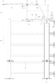
Specifically, as shown in fig. 4, the pre-assembled support includes a bottom plate 31, an H-shaped steel column 29 fixedly connected to the bottom plate 31, a channel steel 26 horizontally arranged on a side surface of the H-shaped steel column 29, and a pre-assembled keel frame 27 detachably connected to the channel steel 26; the bottom of the bottom plate 31 is also provided with a cushion layer 32; the H-shaped steel upright 29 and the embedded screw 30 on the bottom plate 31 are fixed through bolts.
The inner side surface of the preassembled keel frame 27 is provided with a vertical keel 22 which is fixedly connected with a channel steel 26 through a stainless steel bolt group 25, and a reinforcing brace 24 and a transverse keel 50 which are used for supporting the preassembled keel frame 27, the reinforcing brace 24 is connected with two adjacent transverse keels 50 from top to bottom, and the channel steel 26 and the transverse keel 50 which is positioned at the bottommost part are fixedly connected with an H-shaped steel upright 29 through fastening bolts 28.
In this embodiment, the construction of the keel frame 52 installed in the building is substantially identical to that of the preassembled keel frame 27 except that the H-shaped steel column 29 is changed into the concrete column 1 and the bottom plate 31 is not provided.
In the case of the example 2, the following examples are given,
the present embodiment is based on embodiment 1, and the construction of embodiment 1 is performed, including the following steps:
step one, measuring and paying off, equipment assembling and installing: paying off the position of the keel frame 52 at the position between the building layers, marking the installation position, fixing the crane on a proper floor panel 2 after the crane is assembled, and assembling the special-shaped aluminum single plate unit movable support and the pre-assembled support;
step two, as shown in fig. 4 and fig. 9, pre-assembling the special-shaped aluminum veneer units: pre-splicing the prefabricated special-shaped aluminum single plate 3 through a pre-splicing support, wherein the pre-splicing support is provided with a pre-splicing keel frame 27 with the outline consistent with that of the keel frame 52, the special-shaped aluminum single plate 3 is fixed on the pre-splicing keel frame 27 through an aluminum corner connector 23 so as to check whether the special-shaped aluminum single plate 3 is qualified or not, and if the special-shaped aluminum single plate 3 is not qualified, replacing the qualified special-shaped aluminum single plate 3;
step three, hoisting the special-shaped aluminum veneer 3: transporting the special-shaped aluminum veneer unit to the lower part of the building through the special-shaped aluminum veneer unit moving support, and hoisting the special-shaped aluminum veneer 3 to the mounting position between the target floors through a crane;
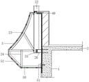
step four, as shown in fig. 8, installing the special-shaped aluminum single plate 3 on a keel frame 52, wherein a transverse keel 50 of the keel frame 52 is fixedly connected with the concrete upright post 1 of the building through a mechanical bottom expanding anchor bolt 51, a vertical keel 22 of the keel frame 52 is fixedly connected with a channel steel 26 embedded in the concrete upright post 1 through a stainless steel bolt group 25, and fireproof rock wool 49 is arranged between the keel frame 52 and the building, so that the installation of the special-shaped aluminum single plate 3 between the current floors is completed;
step five, dismantling and moving a crane: if the interlayer special-shaped aluminum veneers 3 of all the layers are installed, the crane is dismantled; if the construction needs to be continued, the crane is dismantled and is continuously moved to a proper floor for hoisting operation;
when the crane moves, the counterweight block 19 and the connection with the embedded pull rod 18 are removed, the crane is integrally jacked through the jack 13, the telescopic universal wheels 16 are adjusted, the telescopic expanding bottom plate 15 leaves the floor plate 2, and the crane can move;
and step six, circularly executing the step two to the step five until the installation of the interlayer special-shaped aluminum veneers 3 of all the layers is completed.
The details of the present invention are not described in detail since they are prior art.
It is understood that the terms "a" and "an" should be interpreted as meaning that a number of one element or element is one in one embodiment, while a number of other elements is one in another embodiment, and the terms "a" and "an" should not be interpreted as limiting the number.
Although the terms are used more often herein, the possibility of using other terms is not excluded. These terms are used merely to more conveniently describe and explain the nature of the present invention; they are to be construed as being without limitation to any additional limitations that may be imposed by the spirit of the present invention.
The present invention is not limited to the above-mentioned preferred embodiments, and any other products in various forms can be obtained by anyone in the light of the present invention, but any changes in the shape or structure thereof, which have the same or similar technical solutions as the present application, fall within the protection scope of the present invention.
Claims (7)
1. The interlayer complex special-shaped aluminum veneer curtain wall construction structure is characterized by comprising a crane capable of being arranged and disassembled, a special-shaped aluminum veneer unit moving support for transporting special-shaped aluminum veneers and a pre-splicing support for pre-splicing the special-shaped aluminum veneers;
the crane is arranged on a building floor plate of a building;
the top of the special-shaped aluminum single plate unit moving support is provided with an electric hoist, the bottom of the special-shaped aluminum single plate unit moving support is provided with a universal pulley, a rigid turnover frame support for fixedly placing special-shaped aluminum single plates is arranged below the special-shaped aluminum single plate unit moving support, the top of the rigid turnover frame support is provided with a plurality of lifting rings, the lower part of the rigid turnover frame support is provided with a movable bolt, a bottom fixed bolt and a sliding groove for the movable bolt to move up and down so as to fix the special-shaped aluminum single plates, the electric hoist is connected with the lifting rings through a steel wire rope, and the rigid turnover frame support is lifted to carry out special-shaped aluminum single plate transportation;
the pre-assembly support is positioned on the site ground and used for pre-assembly inspection of the special-shaped aluminum veneer before the special-shaped aluminum veneer is installed on a building.
2. The interlayer complex profiled aluminum veneer curtain wall construction structure as claimed in claim 1, wherein the profiled aluminum veneer unit moving bracket is further provided with a movable bolt fixing assembly for fixing a movable bolt, each movable bolt fixing assembly comprises two clamping plates and a plurality of fastening bolts, a reserved hole for the movable bolt to be inserted is provided at the center of each clamping plate, and the clamping plates fix the movable bolt on the hanging rod of the rigid turnover frame bracket by inserting the movable bolt and locking the fastening bolts.
3. The interlayer complex special-shaped aluminum veneer curtain wall construction structure as claimed in claim 1, wherein the crane comprises a crane force bearing support system, a crane stabilizing system, a steel wire rope arranged on the crane force bearing support system, a jack capable of lifting the crane force bearing support system and the crane stabilizing system, and a telescopic universal wheel arranged at the bottom of the crane force bearing support system, the crane force bearing support system is provided with a hoist connected with the steel wire rope, the steel wire rope hoists the special-shaped aluminum veneer through a pulley and an adjusting pulley, and the crane stabilizing system stabilizes the crane force bearing support system by means of its own gravity.
4. The construction structure of the interlayer complex-shaped aluminum veneer curtain wall as claimed in claim 3, wherein the crane stress supporting system is provided with a boom, two ends of the boom are respectively provided with a pulley and a threaded section, the middle part of the boom is welded with a clamp plate, the boom is inserted into a sleeve on a section steel beam of the crane stress supporting system, an anti-slip baffle of the crane stress supporting system is fixed with the threaded section on the boom by bolts, the clamp plate of the boom is in close contact with a first sleeve of the crane stress supporting system, and the boom is fixed on the crane stress supporting system by the clamp plate and the anti-slip baffle.
5. The interlaminar complex profiled aluminum veneer curtain wall construction structure according to claim 4, wherein the crane stabilizing system comprises a weight block for providing gravity, a plurality of connecting ear plates and a plurality of telescopic expanding bottom plates which are arranged at the bottom of the crane stress supporting system.
6. The construction structure of the interlayer complex special-shaped aluminum veneer curtain wall as claimed in any one of claims 1 to 5, wherein the pre-assembled bracket comprises a bottom plate, an H-shaped steel upright post fixedly connected to the bottom plate, a channel steel horizontally arranged on the side surface of the H-shaped steel upright post, and a pre-assembled keel frame detachably connected with the channel steel.
7. The construction structure of the interlayer complex special-shaped aluminum veneer curtain wall as claimed in claim 6, wherein the inner side surface of the pre-assembled keel frame is provided with a vertical keel fixedly connected with the channel steel through a stainless steel bolt group, and a reinforcing brace and a transverse keel for supporting the pre-assembled keel frame, the reinforcing brace is connected with two adjacent transverse keels up and down, and the channel steel and the transverse keel at the bottommost part are fixedly connected with the H-shaped steel upright through fastening bolts.
Priority Applications (1)
| Application Number | Priority Date | Filing Date | Title |
|---|---|---|---|
| CN202220163671.XU CN216787879U (en) | 2022-01-20 | 2022-01-20 | Interlayer complex special-shaped aluminum veneer curtain wall construction structure |
Applications Claiming Priority (1)
| Application Number | Priority Date | Filing Date | Title |
|---|---|---|---|
| CN202220163671.XU CN216787879U (en) | 2022-01-20 | 2022-01-20 | Interlayer complex special-shaped aluminum veneer curtain wall construction structure |
Publications (1)
| Publication Number | Publication Date |
|---|---|
| CN216787879U true CN216787879U (en) | 2022-06-21 |
Family
ID=82015753
Family Applications (1)
| Application Number | Title | Priority Date | Filing Date |
|---|---|---|---|
| CN202220163671.XU Active CN216787879U (en) | 2022-01-20 | 2022-01-20 | Interlayer complex special-shaped aluminum veneer curtain wall construction structure |
Country Status (1)
| Country | Link |
|---|---|
| CN (1) | CN216787879U (en) |
-
2022
- 2022-01-20 CN CN202220163671.XU patent/CN216787879U/en active Active
Similar Documents
| Publication | Publication Date | Title |
|---|---|---|
| WO2020052291A1 (en) | Construction elevator wall-attaching frame mounting platform attached to steel platform formwork and method therefor | |
| CN216076228U (en) | Rail mounted hanging flower basket support device | |
| CN114412192A (en) | Interlayer complex special-shaped aluminum veneer curtain wall and construction method thereof | |
| CN216787879U (en) | Interlayer complex special-shaped aluminum veneer curtain wall construction structure | |
| CN105152052B (en) | Glass curtain wall component installing method | |
| CN210460016U (en) | Integrated form single power lift material platform | |
| WO2023184882A1 (en) | Material lifting device | |
| CN212334397U (en) | Auxiliary tool for hoisting and moving pipeline | |
| CN114436134A (en) | Glass vertical hoisting in-place tool capable of being flexibly adjusted and displaced in multiple directions and use method | |
| CN113309256A (en) | Construction device and construction method for prefabricated shear wall with post-pouring section | |
| CN112761345A (en) | Construction method and operation platform for shaped elevator shaft | |
| CN220149092U (en) | ALC wallboard hoisting device | |
| CN219860047U (en) | Large plate glass lifting device in narrow space | |
| CN212002184U (en) | Hanging basket device for decoration of outer vertical surface of high-rise building | |
| CN104695694A (en) | Worm and gear lead screw lifting type attached scaffold | |
| CN216341070U (en) | Auxiliary positioning device for installation of steel structure net rack | |
| CN212671139U (en) | Efficient and labor-saving wall-hung type decoration tool for roof parapet | |
| CN214090904U (en) | Inverted lifting scaffold with novel hanging assembly | |
| CN213329962U (en) | Split type lifting scaffold | |
| CN214780478U (en) | Lifting type auxiliary lifting device | |
| CN217759925U (en) | BIM-based steel operating platform for light production well | |
| CN220845218U (en) | Curtain wall mounting cross-wall suspension device | |
| CN211396549U (en) | Telescopic folding elevator shaft construction operation platform | |
| CN219044810U (en) | Simple material lifting device in hoistway | |
| CN215107150U (en) | Stiff beam pouring support structure |
Legal Events
| Date | Code | Title | Description |
|---|---|---|---|
| GR01 | Patent grant | ||
| GR01 | Patent grant |