CN216756725U - Assembly type noise-reduction green aggregate production line - Google Patents
Assembly type noise-reduction green aggregate production line Download PDFInfo
- Publication number
- CN216756725U CN216756725U CN202220253565.0U CN202220253565U CN216756725U CN 216756725 U CN216756725 U CN 216756725U CN 202220253565 U CN202220253565 U CN 202220253565U CN 216756725 U CN216756725 U CN 216756725U
- Authority
- CN
- China
- Prior art keywords
- dust
- belt
- aggregate
- production line
- double
- Prior art date
- Legal status (The legal status is an assumption and is not a legal conclusion. Google has not performed a legal analysis and makes no representation as to the accuracy of the status listed.)
- Active
Links
Images


Landscapes
- Combined Means For Separation Of Solids (AREA)
Abstract
The utility model discloses an assembly type noise reduction type green aggregate production line which comprises a vibrating feeder, a heavy hammer type crusher, a first double-excitation vibrating screen, an aggregate shaping machine and a second double-excitation vibrating screen, wherein the vibrating feeder is installed inside a foundation pit, the heavy hammer type crusher is arranged on one side of the output end of the vibrating feeder, the output end of the heavy hammer type crusher is connected with one end of a crushed material conveying belt, one end of an aggregate discharging belt is arranged below the aggregate shaping machine, the other end of the aggregate discharging belt extends out of the foundation pit and is connected with the second double-excitation vibrating screen, and a dust falling box is installed above the residue soil discharging belt. This green aggregate production line of type of making an uproar falls in assembled handles the mode that screening plant passes through the conveyer belt assembly through each aggregate for whole production line can carry out optimal design according to the topography, even also can high-efficient stable installation and use aggregate production line on some comparatively rugged ground.
Description
Technical Field
The utility model relates to the technical field of mine industry, in particular to an assembly type noise reduction type green aggregate production line.
Background
The green sand and stone aggregate production line is the trend of future development of the mine industry, the production line is also the direction from the development of rough type to the development of environment protection and energy saving of the sand and stone aggregate production enterprises at present, the traditional sand and stone aggregate production line screens and processes the materials by grading through different devices, but the mode has some defects in the actual generation process, such as:
1. the existing aggregate production line completely independently operates all devices, aggregates among all the devices need to be transported and thrown in by vehicles, and the existing aggregate production line is greatly interfered by site factors and cannot be stably installed and used in rugged terrains such as mines;
2. the existing aggregate production line often generates larger noise during feeding and crushing, even though a mode of installing sound insulation walls around the field is adopted, the existing aggregate production line still causes larger pollution to the surrounding environment, and does not meet the green and environment-friendly call in the current industry;
3. the existing aggregate production line can produce a large amount of dust during production, and although some dust settling devices are arranged, the dust settling effect of the outdoor dust settling device is not very ideal, and a large amount of dust is always scattered to the surrounding environment
Aiming at the problems, innovative design is urgently needed on the basis of the original aggregate production line.
Disclosure of Invention
The utility model aims to provide an assembly type noise-reduction green aggregate production line, which aims to solve the problems of limited installation environment and serious environmental pollution caused by noise and dust in the background technology.
In order to achieve the purpose, the utility model provides the following technical scheme: an assembly type noise reduction type green aggregate production line comprises a vibrating feeder, a heavy hammer type crusher, a first double-excitation vibrating screen, an aggregate shaping machine and a second double-excitation vibrating screen, wherein the vibrating feeder is installed inside a foundation pit, the heavy hammer type crusher is arranged on one side of the output end of the vibrating feeder, the output end of the heavy hammer type crusher is connected with one end of a crushed material conveying belt, the other end of the crushed material conveying belt extends out of the foundation pit and is connected with the first double-excitation vibrating screen, a muck conveying belt is arranged on one side of the vibrating feeder, the lower end of the muck conveying belt is connected with a muck transit belt, the lower end of the muck transit belt is connected with one end of a muck output belt, a soil removing vibrating screen is installed on one side of the first double-excitation vibrating screen, one end of the muck output belt penetrates through the lower part of the soil removing vibrating screen, and the output end of the soil removing vibrating screen is connected with the shaping conveying belt, the end-to-end connection of plastic conveyer belt has the aggregate trimmer, the below of aggregate trimmer is provided with the one end in aggregate play material area, the other end in aggregate play material area stretches out the foundation ditch and is connected with the second dual excitation shale shaker, the dust falling box is installed to the top in dregs output area.
Preferably, the vibrating feeder, the heavy hammer type crusher and the aggregate shaping machine are all located in a foundation pit below the ground, and the upper surfaces of the foundation pit where the vibrating feeder, the heavy hammer type crusher and the aggregate shaping machine are located are covered by a foam board.
Adopt above-mentioned technical scheme for the cystosepiment can shelter from and absorb the noise in the foundation ditch, with produced noise intensity during reduction construction.
Preferably, a return cage material conveying belt is connected between the first double-excitation vibrating screen and the vibrating feeder, a screening output belt is arranged below the first double-excitation vibrating screen, and one end of the screening output belt is connected with a feeding end of the soil removing vibrating screen.
By adopting the technical scheme, the larger aggregate screened out by the first double-excitation vibrating screen can be conveyed to the vibrating feeder again through the returning cage material conveying belt to be thrown into the heavy hammer type crusher for secondary crushing.
Preferably, the lower surface of dust falling box is embedded to be installed dust fall fan, the internally mounted of dust falling box has double-end motor.
Adopt above-mentioned technical scheme for the dust fall fan can inhale the inside of dust fall box with the air that contains the dust.
Preferably, the output end of the second double-excitation vibrating screen is connected with a first discharging belt, a second discharging belt, a third discharging belt and a fourth discharging belt respectively, the tail end of the fourth discharging belt is provided with the powder concentrator, and the output end of the powder concentrator is connected with a fifth discharging belt.
Adopt above-mentioned technical scheme for the material can convey to different material storage positions through first ejection of compact area, second ejection of compact area, third ejection of compact area and fourth ejection of compact area according to the particle size of difference, utilizes the selection powder machine to carry out the selection powder to the finest material through the selection by winnowing technology simultaneously.
Preferably, the upper end of double-end motor is fixed with the breather plate, the surface of breather plate evenly sets up there is the gas pocket, double-end motor's lower extreme is fixed with the dust filter plate, the surface of dust filter plate evenly is provided with the filter screen, the gas pocket sets up for concentric with the filter screen.
By adopting the technical scheme, when the filter screen rotates to the position of the dust storage pipe, the air holes can filter the air containing dust injected into the filter screen through the dust storage pipe.
Preferably, the dust falling box is internally provided with a dust storage pipe for storing dust, and the upper end surface and the lower end surface of the dust storage pipe are respectively attached to the outer surfaces of the ventilation plate and the dust filter plate.
By adopting the technical scheme, the dust in the dust storage pipe cannot leak when the ventilation plate and the dust filter plate rotate.
Preferably, fall the inside of dirt box and offer the play dirt pipe that is used for deriving the dust, and go out the inboard surface of dirt pipe and run through by the baffle to the upper end of going out the dirt pipe is connected with the recoil pipe, the lower extreme that goes out the dirt pipe is the design of slant muck output tape, the upper surface that falls the dirt box is run through by the blast pipe, the baffle has magnetism, and is connected with the spring between baffle and the dust fall box to the baffle is sliding connection with falling the dirt box.
By adopting the technical scheme, the dust in the dust outlet pipe can leak to the muck output belt and be discharged after sliding on the baffle plate.
Preferably, a rotary disc is fixed on the lower surface of the dust filtering plate, a magnet is embedded in the lower surface of the rotary disc, and the magnetic pole of the magnet at one end opposite to the baffle is opposite.
Adopt above-mentioned technical scheme for when the carousel drove magnet and rotates to between 2 baffles, the baffle can let the dust let to the inside slip of dust fall box under the drive of spring.
Preferably, the lower end surface of the exhaust pipe is attached to the upper surface of the dust filter plate, the upper end surface of the recoil pipe is attached to the lower surface of the dust filter plate, and the circle center of the lower end surface of the exhaust pipe coincides with the circle center of the upper end surface of the recoil pipe.
Adopt above-mentioned technical scheme for the air current can drive the dust of jam on the filter screen and blow out through the blast pipe when recoil pipe and filter screen coincide, and the dust that blows out can be inhaled dust falling box again under dust falling fan's effect.
Compared with the prior art, the utility model has the beneficial effects that: this green aggregate production line of type of making an uproar falls in assembled:
1. by the mode that all the aggregate processing and screening devices are assembled together through the conveying belt, the whole production line can be optimally designed according to the terrain, and the aggregate production line can be efficiently and stably installed and used even on rugged ground;
2. the vibrating feeder and the heavy hammer crusher with high noise are arranged and used in the foundation pit, and the sound insulation material is covered above the foundation pit, so that the problem of high noise of a traditional aggregate production line is solved by using the foundation pit which is relatively closed, and the utilization rate of the space is improved to the maximum extent by using the foundation pit;
3. through falling the mode that the dust box inhales the inside dust of foundation ditch and filters and collect for the inside dust of foundation ditch can arrange to the upper surface in dregs output area through going out the dirt pipe, and finally concentrate the dust and discharge to dregs collection department and wait for the clearance under the transport in dregs output area, thereby realized the efficient dust fall.
Drawings
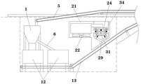
FIG. 1 is a schematic top sectional view of the present invention;
FIG. 2 is a schematic view of a connection overlooking structure of the vibrating feeder and the heavy hammer type crusher;
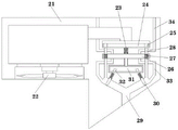
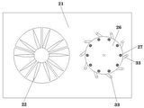
fig. 3 is a schematic cross-sectional view of the dust falling box and the dust falling fan according to the present invention;
FIG. 4 is a schematic cross-sectional view of the connection between the dual head motor and the aeration panel according to the present invention;
FIG. 5 is a schematic sectional side view of the dust box and the back-flushing pipe according to the present invention;
fig. 6 is a schematic view of a connection depression cross-sectional structure of the dust-settling box and the recoil pipe of the present invention.
In the figure: 1. a vibrating feeder; 2. a heavy hammer crusher; 3. a crushed material conveyor belt; 4. a first dual-excitation vibrating screen; 5. a cage returning material conveying belt; 6. a muck conveyor belt; 7. a muck transit zone; 8. a muck output belt; 9. screening the output belt; 10. a soil removal vibrating screen; 11. shaping the conveyor belt; 12. an aggregate shaper; 13. discharging the aggregate from the material belt; 14. a second dual-excitation vibrating screen; 15. a first discharging belt; 16. a second discharging belt; 17. a third discharging belt; 18. a fourth discharging belt; 19. selecting a powder machine; 20. a fifth discharging belt; 21. a dust falling box; 22. a dust-settling fan; 23. a double-headed motor; 24. a breather plate; 25. air holes; 26. a dust filter plate; 27. filtering with a screen; 28. a dust storage pipe; 29. a dust outlet pipe; 30. a baffle plate; 31. a turntable; 32. a magnet; 33. back flushing the pipe; 34. and (4) exhausting the gas.
Detailed Description
The technical solutions in the embodiments of the present invention will be clearly and completely described below with reference to the drawings in the embodiments of the present invention, and it is obvious that the described embodiments are only a part of the embodiments of the present invention, and not all of the embodiments. All other embodiments, which can be derived by a person skilled in the art from the embodiments given herein without making any creative effort, shall fall within the protection scope of the present invention.
Referring to fig. 1-6, the present invention provides a technical solution: an assembly type noise reduction type green aggregate production line comprises a vibrating feeder 1, a heavy hammer type crusher 2, a crushed material conveyor belt 3, a first double-excitation vibrating screen 4, a returning cage material conveyor belt 5, a muck conveyor belt 6, a muck transferring belt 7, a muck output belt 8, a screening output belt 9, a soil removal vibrating screen 10, a shaping conveyor belt 11, an aggregate shaping machine 12, an aggregate discharging belt 13, a second double-excitation vibrating screen 14, a first discharging belt 15, a second discharging belt 16, a third discharging belt 17, a fourth discharging belt 18, a powder selecting machine 19, a fifth discharging belt 20, a dust falling box 21, a dust falling fan 22, a double-end motor 23, a vent plate 24, an air hole 25, a dust filtering plate 26, a filter screen 27, a dust storage pipe 28, a dust discharging pipe 29, a baffle 30, a rotary table 31, a magnet 32, a back flushing pipe 33 and an exhaust pipe 34, wherein the vibrating feeder 1 is installed inside a foundation pit, the heavy hammer type crusher 2 is arranged on one side of the output end of the vibrating feeder 1, the output of heavy hammer crusher 2 is connected with 3 one ends of broken material conveyer belt, the other end of broken material conveyer belt 3 stretches out the foundation ditch and is connected with first pair excitation shale shaker 4, vibrating feeder 1, heavy hammer crusher 2 and aggregate trimmer 12 all are located the foundation ditch of ground below, vibrating feeder 1, heavy hammer crusher 2 and aggregate trimmer 12 place foundation ditch upper surface are covered by the cystosepiment, utilize the cystosepiment to cover and install vibrating feeder 1, the mode of heavy hammer crusher 2 and aggregate trimmer 12 place foundation ditch, make the inside vibrating feeder 1 of foundation ditch, the produced noise of heavy hammer crusher 2 and the work of aggregate trimmer 12 can be sheltered from by the cystosepiment, in order to reduce the noise size that spreads the foundation ditch.
As shown in fig. 1, a muck conveyor belt 6 is arranged at one side of a vibrating feeder 1, a muck transit belt 7 is connected at the lower end of the muck conveyor belt 6, one end of a muck output belt 8 is connected at the lower end of the muck transit belt 7, a soil removing vibrating screen 10 is installed at one side of a first double-excitation vibrating screen 4, one end of the muck output belt 8 passes through the lower part of the soil removing vibrating screen 10, the output end of the soil removing vibrating screen 10 is connected with a shaping conveyor belt 11, the tail end of the shaping conveyor belt 11 is connected with an aggregate shaping machine 12, one end of an aggregate discharging belt 13 is arranged below the aggregate shaping machine 12, the other end of the aggregate discharging belt 13 extends out of a foundation pit and is connected with a second double-excitation vibrating screen 14, a returning cage material conveyor belt 5 is connected between the first double-excitation vibrating screen 4 and the vibrating feeder 1, a screening output belt 9 is arranged below the first double-excitation vibrating screen 4, one end of the screening output belt 9 is connected with the feeding end of the soil removing vibrating screen 10, aggregates which are screened by the first double-excitation vibrating screen 4 and are not ground completely are conveyed to the vibrating feeder 1 again through the returning cage material conveying belt 5 to be thrown into the heavy hammer type crusher 2 for secondary grinding, the specific model of the vibrating feeder 1 is GZD-4218, the specific model of the heavy hammer type crusher 2 is ZPCS-2024, the specific models of the first double-excitation vibrating screen 4 and the second double-excitation vibrating screen 14 are 3YK-2670, the specific model of the aggregate shaping machine 12 is PCL-1450, and the specific model of the powder concentrator 19 is N-3500.
As shown in fig. 2-6, a dust falling box 21 is installed above the residue soil output belt 8, a dust falling fan 22 is installed on the lower surface of the dust falling box 21 in an embedded manner, a double-headed motor 23 is installed inside the dust falling box 21, the output end of the second double-excitation vibrating screen 14 is respectively connected with a first material outlet belt 15, a second material outlet belt 16, a third material outlet belt 17 and a fourth material outlet belt 18, a powder concentrator 19 is installed at the tail end of the fourth material outlet belt 18, the output end of the powder concentrator 19 is connected with a fifth material outlet belt 20, an air vent plate 24 is fixed at the upper end of the double-headed motor 23, air holes 25 are uniformly formed in the outer surface of the air vent plate 24, a dust filter plate 26 is fixed at the lower end of the double-headed motor 23, a filter screen 27 is uniformly arranged on the outer surface of the dust filter plate 26, the air holes 25 and the filter screen 27 are concentrically arranged, a dust storage pipe 28 for storing dust is arranged inside the dust falling box 21, the upper and lower end surfaces of the dust storage pipe 28 are respectively attached to the outer surfaces of the air vent plate 24 and the dust filter plate 26, a dust outlet pipe 29 for guiding out dust is arranged in the dust falling box 21, the inner side surface of the dust outlet pipe 29 is penetrated through by a baffle 30, the upper end of the dust outlet pipe 29 is connected with a recoil pipe 33, the lower end of the dust outlet pipe 29 is designed to be an inclined residue output belt 8, the upper surface of the dust falling box 21 is penetrated through by an exhaust pipe 34, the baffle 30 is magnetic, a spring is connected between the baffle 30 and the dust falling box 21, the baffle 30 and the dust falling box 21 are in sliding connection, a rotary disc 31 is fixed on the lower surface of the dust filtering plate 26, a magnet 32 is embedded on the lower surface of the rotary disc 31, the magnetic poles of the magnet 32 and the opposite end of the baffle 30 are opposite, the lower end surface of the exhaust pipe 34 is adhered to the upper surface of the dust filtering plate 26, the upper end surface of the recoil pipe 33 is adhered to the lower surface of the dust filtering plate 26, the circle center of the lower end surface of the exhaust pipe 34 is overlapped with the circle center of the upper end surface of the recoil pipe 33, and the dust in the foundation pit is sucked into the dust falling box 21 for filtering and collecting, make the inside dust of foundation ditch arrange to the upper surface of sediment output area 8 through going out dirt pipe 29, and finally concentrate the dust under the transport of sediment output area 8 and discharge to sediment collection department and wait for the clearance, thereby realized the efficient dust fall, utilize double-end motor 23 to drive breather plate 24 and the mode that dust filter plate 26 rotated simultaneously, utilize the dislocation of gas pocket 25 and filter screen 27 and dust storage pipe 28 and play dirt pipe 29, accomplish the filtration and the discharge to the dust, utilize the air current to carry out the back flush to filter screen 27 through recoil pipe 33 and blast pipe 34 simultaneously, in order to prevent that filter screen 27 from being blockked up by the dust in long-time use.
The working principle is as follows: when the assembly type noise-reduction green aggregate production line is used, firstly, a first double-excitation vibrating screen 4, a soil-removal vibrating screen 10, a second double-excitation vibrating screen 14 and a powder concentrator 19 are respectively installed at proper positions according to terrain, then, a vibrating feeder 1, a heavy hammer crusher 2 and an aggregate shaping machine 12 are installed at the bottom of a foundation pit, a cage material returning conveyor belt 5 is installed between the vibrating feeder 1 and the first double-excitation vibrating screen 4, a muck conveyor belt 6 and a muck transferring belt 7 are installed at one side of the vibrating feeder 1, then, a crushed material conveyor belt 3 is installed at a discharge port of the heavy hammer crusher 2, the other end of the crushed material conveyor belt 3 is connected with a feed port of the first double-excitation vibrating screen 4, then, one end of a muck output belt 8 is installed below an output end of the muck transferring belt 7, and the other end of the muck output belt 8 passes through the lower part of the soil-removal vibrating screen 10 to be fixed on the ground, then a screening output belt 9 is installed between a first double-excitation vibrating screen 4 and a soil removing vibrating screen 10, a shaping conveyor belt 11 is installed between the soil removing vibrating screen 10 and an aggregate shaping machine 12, the shaping conveyor belt 11 is installed between the output end of the aggregate shaping machine 12 and the feed end of a second double-excitation vibrating screen 14, then a first material outlet belt 15, a second material outlet belt 16, a third material outlet belt 17 and a fourth material outlet belt 18 which face different directions are respectively installed at the output end of the second double-excitation vibrating screen 14, the tail end of the fourth material outlet belt 18 is connected with the input end of a powder concentrator 19, a fifth material outlet belt 20 is installed at the output end of the powder concentrator 19, and finally a dust falling box 21 is installed in a foundation pit and the discharge port of a dust outlet pipe 29 is aligned with a residue soil output belt 8, so that the installation of an aggregate production line is completed;
when the crusher is used, firstly, large raw stones are fed into the vibrating feeder 1 from a feeding hole of the vibrating feeder 1, the raw stones are fed into the heavy hammer crusher 2 by the vibrating feeder 1 to be crushed, the crushed materials are conveyed to two first double-excitation vibrating sieves 4 through the crushed material conveying belt 3 to be sieved, the sieved return cage materials are conveyed to the heavy hammer crusher 2 through the return cage material conveying belt 5 to be secondarily crushed, the materials crushed by the heavy hammer crusher 2 are conveyed to the first double-excitation vibrating sieves 4 again, muck is directly leaked out through the muck conveying belt 6 and the muck transit belt 7 in the crushing process and is conveyed to the muck output belt 8, at the moment, other materials except the return cage materials screened by the first double-excitation vibrating sieves 4 are conveyed to the positions except the muck vibrating sieves 10 through the screening output belt 9 to screen muck, and the screened muck falls on the muck output belt 8 to be conveyed away;
the material is conveyed to two aggregate shaping machines 12 through a shaping conveyor belt 11 for shaping treatment, the treated material is conveyed to two second double-excitation vibration sieves 14 through aggregate discharging belts 13 for sieving to obtain finished material with various specifications, the finished material is conveyed to a finished product bin for temporary storage through a first discharging belt 15, a second discharging belt 16, a third discharging belt 17 and a fourth discharging belt 18, the finest raw material product enters a powder concentrator 19 from the fourth discharging belt 18, the powder concentrator 19 is used for adding a winnowing process for powder concentration, and the powder is conveyed to the finished product bin for temporary storage through a fifth discharging belt 20 after the powder concentration is finished;
in the working process of the vibrating feeder 1, the heavy hammer crusher 2 and the aggregate shaping machine 12, firstly, the dust falling fan 22 and the double-head motor 23 inside the dust falling box 21 are started, the dust falling fan 22 rotates to convey air containing a large amount of dust inside a foundation pit to the ventilating plate 24, when the double-head motor 23 drives the air hole 25 to rotate to a position coinciding with the dust storage pipe 28 through the ventilating plate 24, at the moment, the air is filtered by the filter screen 27 on the dust filter plate 26 and then discharged into the dust discharge pipe 29, the dust is retained inside the dust storage pipe 28 under the blocking of the filter screen 27, clean air is subjected to back flushing from bottom to top by the back flushing pipe 33 under the blocking of the baffle 30 to the filter screen 27 not coinciding with the dust storage pipe 28, so that a small amount of dust blocked on the filter screen 27 can be discharged through the exhaust pipe 34 under the driving of air flow, after a period of time, the double-head motor 23 simultaneously drives the ventilating plate 24 and the dust filter plate 26 to rotate, at this time, the filter screen 27 is not overlapped with the dust storage pipe 28 or the backflushing pipe 33, the dust filtering plate 26 drives the magnet 32 on the rotating turntable 31 to be right located between the 2 baffles 30, the baffles 30 lose repulsive force of the magnet 32 and slide under the driving of the spring and leak dust to the lower end of the dust outlet pipe 29, the dust outlet pipe 29 leaks the dust to the residue soil output belt 8 and is discharged along with the residue soil, and since the dust outlet pipe 29 does not have air flow at this time, the dust cannot be blown away by the air flow, and along with the work of the double-end motor 23 again, the air hole 25, the filter screen 27 and the magnet 32 realize the filtering collection of the dust and the backflushing cleaning of the filter screen 27 through periodic rotation.
Although embodiments of the present invention have been shown and described, it will be appreciated by those skilled in the art that various changes, modifications, substitutions and alterations can be made in these embodiments without departing from the principles and spirit of the utility model, the scope of which is defined in the appended claims and their equivalents.
Claims (10)
1. The utility model provides a green aggregate production line of type of making an uproar falls in assembled, includes vibrating feeder (1), heavy hammer crusher (2), first dual excitation shale shaker (4), aggregate trimmer (12) and second dual excitation shale shaker (14), its characterized in that: the device comprises a vibrating feeder (1), a heavy hammer crusher (2) is arranged on one side of the output end of the vibrating feeder (1), the output end of the heavy hammer crusher (2) is connected with one end of a crushed material conveying belt (3), the other end of the crushed material conveying belt (3) extends out of the foundation pit and is connected with a first double-excitation vibrating screen (4), a muck conveying belt (6) is arranged on one side of the vibrating feeder (1), the lower end of the muck conveying belt (6) is connected with a muck transit belt (7), the lower end of the muck transit belt (7) is connected with one end of a muck output belt (8), a soil removal vibrating screen (10) is installed on one side of the first double-excitation vibrating screen (4), one end of the muck output belt (8) penetrates through the lower part of the soil removal vibrating screen (10), the output end of the soil removal vibrating screen (10) is connected with a shaping conveying belt (11), the end-to-end connection of plastic conveyer belt (11) has aggregate trimmer (12), the below of aggregate trimmer (12) is provided with the one end of aggregate play material area (13), the other end of aggregate play material area (13) stretches out the foundation ditch and is connected with second double excitation shale shaker (14), dust falling box (21) are installed to the top of dregs output tape (8).
2. The assembly type noise-reduction green aggregate production line of claim 1, which is characterized in that: the vibrating feeder (1), the heavy hammer type crusher (2) and the aggregate shaping machine (12) are all located in a foundation pit below the ground, and the upper surfaces of the foundation pit where the vibrating feeder (1), the heavy hammer type crusher (2) and the aggregate shaping machine (12) are located are covered by a foam board.
3. The assembly type noise-reduction green aggregate production line according to claim 1, characterized in that: be connected with back cage material conveyer belt (5) between first double excitation shale shaker (4) and vibrating feeder (1), the below of first double excitation shale shaker (4) is provided with screening output tape (9), the one end of screening output tape (9) is connected with the feed end that removes native shale shaker (10).
4. The assembly type noise-reduction green aggregate production line of claim 1, which is characterized in that: dust fall fan (22) are installed to the lower surface embedded type of dust fall box (21), the internally mounted of dust fall box (21) has double-end motor (23).
5. The assembly type noise-reduction green aggregate production line of claim 1, which is characterized in that: the output end of the second double-excitation vibrating screen (14) is connected with a first discharging belt (15), a second discharging belt (16), a third discharging belt (17) and a fourth discharging belt (18) respectively, the tail end of the fourth discharging belt (18) is provided with a powder concentrator (19), and the output end of the powder concentrator (19) is connected with a fifth discharging belt (20).
6. The assembly type noise-reduction green aggregate production line of claim 4, wherein: the upper end of double-end motor (23) is fixed with air vent plate (24), air hole (25) have evenly been seted up to the surface of air vent plate (24), the lower extreme of double-end motor (23) is fixed with dust filter plate (26), the surface of dust filter plate (26) evenly is provided with filter screen (27), air hole (25) and filter screen (27) are concentric setting.
7. The assembly type noise-reduction green aggregate production line of claim 1, which is characterized in that: the dust falling box (21) is internally provided with a dust storage pipe (28) for storing dust, and the upper end surface and the lower end surface of the dust storage pipe (28) are respectively attached to the outer surfaces of the ventilation plate (24) and the dust filtering plate (26).
8. The assembly type noise-reduction green aggregate production line of claim 1, which is characterized in that: fall the inside of dirt box (21) and offer play dirt pipe (29) that are used for deriving the dust, and the inboard surface of going out dirt pipe (29) is run through by baffle (30) to the upper end of going out dirt pipe (29) is connected with recoil pipe (33), the lower extreme of going out dirt pipe (29) is the design of slant muck output tape (8), the upper surface of falling dirt box (21) is run through by blast pipe (34), baffle (30) have magnetism, and are connected with the spring between baffle (30) and the dust box (21) of falling to baffle (30) and dust box (21) of falling are sliding connection.
9. The assembly type noise-reduction green aggregate production line of claim 6, wherein: the lower surface of the dust filtering plate (26) is fixed with a rotary disc (31), a magnet (32) is embedded in the lower surface of the rotary disc (31), and the magnetic poles of the magnet (32) and one end of the baffle (30) in the opposite direction are opposite.
10. The assembly type noise-reduction green aggregate production line of claim 8, wherein: the lower end face of the exhaust pipe (34) is attached to the upper surface of the dust filtering plate (26), the upper end face of the backflushing pipe (33) is attached to the lower surface of the dust filtering plate (26), and the circle center of the lower end face of the exhaust pipe (34) coincides with the circle center of the upper end face of the backflushing pipe (33).
Priority Applications (1)
| Application Number | Priority Date | Filing Date | Title |
|---|---|---|---|
| CN202220253565.0U CN216756725U (en) | 2022-02-08 | 2022-02-08 | Assembly type noise-reduction green aggregate production line |
Applications Claiming Priority (1)
| Application Number | Priority Date | Filing Date | Title |
|---|---|---|---|
| CN202220253565.0U CN216756725U (en) | 2022-02-08 | 2022-02-08 | Assembly type noise-reduction green aggregate production line |
Publications (1)
| Publication Number | Publication Date |
|---|---|
| CN216756725U true CN216756725U (en) | 2022-06-17 |
Family
ID=81956438
Family Applications (1)
| Application Number | Title | Priority Date | Filing Date |
|---|---|---|---|
| CN202220253565.0U Active CN216756725U (en) | 2022-02-08 | 2022-02-08 | Assembly type noise-reduction green aggregate production line |
Country Status (1)
| Country | Link |
|---|---|
| CN (1) | CN216756725U (en) |
-
2022
- 2022-02-08 CN CN202220253565.0U patent/CN216756725U/en active Active
Similar Documents
| Publication | Publication Date | Title |
|---|---|---|
| JP5770780B2 (en) | Debris treatment equipment | |
| CN111167589B (en) | Dry sand making process | |
| CN110369262B (en) | Aggregate sorting equipment for road and bridge construction | |
| CN210079794U (en) | Waste recovery device is used in magnetic material production | |
| CN107030081A (en) | A kind of used by oscillating screen feeds dustproof dust-collecting equipment | |
| CN114160411B (en) | Sieving mechanism for flour processing and working method thereof | |
| CN117065902B (en) | Multistage broken sand making machine | |
| CN213611933U (en) | A raw materials grinder for chemical industry | |
| CN216756725U (en) | Assembly type noise-reduction green aggregate production line | |
| CN113578510A (en) | Production system for machine-made sand concrete | |
| CN218610428U (en) | Building construction grit screening plant | |
| CN114345529A (en) | Assembly type noise-reduction green aggregate production line | |
| CN116441170A (en) | Grit sorting and cleaning integrated machine for civil engineering | |
| CN212732951U (en) | Vibrating type standard vibrating screen machine | |
| CN212418318U (en) | Automatic material collecting device for screening | |
| CN209222636U (en) | A kind of clinker iron filings separation system | |
| CN210966342U (en) | Sorting, treating and recycling device for waste incineration slag | |
| CN114082650A (en) | Vertical multistage mining coarse screening device | |
| CN211726495U (en) | A grit screening plant for construction | |
| CN109365298A (en) | A kind of clinker iron filings separation system | |
| CN216225293U (en) | High-efficient grit screening plant for municipal works construction | |
| CN216322187U (en) | Waste incinerator slag treatment device | |
| CN112934694B (en) | Gangue screening installation | |
| CN218945650U (en) | Stone removing machine with collecting function | |
| CN220716688U (en) | Automatic sorting machine for materials for building material production |
Legal Events
| Date | Code | Title | Description |
|---|---|---|---|
| GR01 | Patent grant | ||
| GR01 | Patent grant |