CN216710643U - Special full-automatic production line for producing torsional springs - Google Patents
Special full-automatic production line for producing torsional springs Download PDFInfo
- Publication number
- CN216710643U CN216710643U CN202220028265.2U CN202220028265U CN216710643U CN 216710643 U CN216710643 U CN 216710643U CN 202220028265 U CN202220028265 U CN 202220028265U CN 216710643 U CN216710643 U CN 216710643U
- Authority
- CN
- China
- Prior art keywords
- conveyor
- production line
- torsion spring
- chain
- automatic production
- Prior art date
- Legal status (The legal status is an assumption and is not a legal conclusion. Google has not performed a legal analysis and makes no representation as to the accuracy of the status listed.)
- Active
Links
Images


Landscapes
- Preliminary Treatment Of Fibers (AREA)
Abstract
The utility model discloses a special full-automatic production line for producing a torsion spring, which comprises a torsion spring machine, a chain plate conveyor, support legs and a material collecting box, wherein the chain plate conveyor is arranged on one side of the torsion spring machine, the bottom of the chain plate conveyor is provided with a plurality of support legs, the material collecting box is arranged on the right side of the chain plate conveyor, the inner side of the chain plate conveyor is rotatably provided with a conveying belt through a rotating shaft, the bottom of the chain plate conveyor is provided with a cleaning mechanism, and the cleaning mechanism comprises two base columns symmetrically fixed on the bottom surface of the chain plate conveyor; through set up clearance mechanism on chain scraper conveyor, can be at chain scraper conveyor operation period, the clearance is cleaned on continuous surface to conveyor belt, avoids the torsional spring that the dirt and the smear metal on conveyor belt surface will carry to make dirty to improve the product cleanliness factor of torsional spring, also avoid bringing the burden for the washing step of follow-up torsional spring, improve production efficiency.
Description
Technical Field
The utility model belongs to the technical field of torsional spring production equipment, and particularly relates to a full-automatic production line special for torsional spring production.
Background
The full-automatic production line of torsional spring is a special production line with production torsional spring, mainly comprises torsional spring machine, chain scraper conveyor, receipts workbin etc. and the preliminary shaping of torsional spring is accomplished earlier to the torsional spring machine, then carries the torsional spring to chain scraper conveyor through the conveyer belt at torsional spring machine top on, and the automated production of torsional spring can be accomplished to the receipts workbin in to the transport of rethread chain scraper conveyor.
When the existing full-automatic production line for the torsion spring is used, due to the fact that no structure for cleaning the inner side conveying belt is arranged on the chain plate conveyor, dirt and cutting scraps on the conveying belt cannot be effectively cleaned, the torsion spring is easy to be polluted and influenced when conveyed on the conveying belt, burden is brought to subsequent product cleaning steps, and the defects exist.
SUMMERY OF THE UTILITY MODEL
The utility model aims to provide a full-automatic production line special for producing a torsion spring, which aims to solve the problems in the background technology.
In order to achieve the purpose, the utility model provides the following technical scheme: a full-automatic production line special for torsion spring production comprises a torsion spring machine, a chain scraper conveyor, supporting legs and a collecting box, wherein the chain scraper conveyor is arranged on one side of the torsion spring machine, a plurality of supporting legs are arranged at the bottom of the chain scraper conveyor, the collecting box is arranged on the right side of the chain scraper conveyor, a conveying belt is arranged on the inner side of the chain scraper conveyor in a rotating mode through a rotating shaft, a cleaning mechanism is arranged at the bottom of the chain scraper conveyor and comprises two base columns which are symmetrically fixed on the surface of the bottom of the chain scraper conveyor, a base sleeve is sleeved on the surface of each base column in a sliding mode, two side seats are fixed on one side of each base sleeve, an L-shaped supporting plate is fixed on one side of each side seat, a cleaning roller is arranged between the L-shaped supporting plates in a rotating mode, cleaning cotton in contact with the conveying belt is arranged on the surface of the cleaning roller, the cleaning roller comprises an outer roller and an inner roller, interior roller passes through the bearing and rotates with outer roller to be connected, and clean cotton installation roller surface outside, the inside of foundation pillar has been seted up interior spout, just the inside of interior spout is provided with interior slider and spring, the sideslip has all been seted up to the both sides inner wall of interior spout, and two all be provided with the connecting block in the sideslip, interior slider is fixed with the base sleeve through two connecting blocks.
Preferably, the both ends of interior roller all are provided with T shape pole, two the strip-shaped mouth of hanging has all been seted up on the top of L shape fagging, two T shape pole imbeds respectively to the strip-shaped mouth of hanging on two L shape fagging tops in, be equipped with coupling mechanism between T shape pole and the L shape fagging.
Preferably, the connecting mechanism comprises a limiting clamping plate, a screw, a butterfly nut and a limiting rod, the screw is fixed on the surface of the L-shaped supporting plate, the limiting clamping plate and the butterfly nut are rotatably sleeved on the surface of the screw, the butterfly nut is in threaded connection with the screw, the limiting rod is fixed on the surface of the T-shaped rod, a round hole is formed in the top end of the limiting clamping plate, and the top end of the limiting clamping plate is sleeved on the limiting rod.
Preferably, the bottom end of the limiting clamping plate is provided with a sleeve hole, and the size of the sleeve hole corresponds to that of the screw rod.
Preferably, an inner guide rod is fixed on the inner side of the inner sliding groove, and the inner sliding block and the spring are sleeved on the inner guide rod.
Preferably, a slot is formed in one side of the side seat, the bottom end of the L-shaped supporting plate is inserted into the slot, and the L-shaped supporting plate and the side seat are fixed through bolts.
Preferably, a top seat is fixed at the top end of the base column, and the top seat is fixed on the bottom surface of the chain scraper conveyor through bolts.
Compared with the prior art, the utility model has the beneficial effects that:
1. through set up clearance mechanism on chain scraper conveyor, can be at chain scraper conveyor operation period, the clearance is cleaned on continuous surface to conveyor belt, avoids the torsional spring that the dirt and the smear metal on conveyor belt surface will carry to make dirty to improve the product cleanliness factor of torsional spring, also avoid bringing the burden for the washing step of follow-up torsional spring, improve production efficiency.
2. Through the connecting mechanism who sets up for the cleaning roller can be quick realize the installation and dismantle between two L shape faggings, has improved the assembly efficiency of cleaning roller on the one hand, and on the other hand has also brought the convenience for the clearance change of follow-up cleaning roller, improves subsequent maintenance convenience.
Drawings
FIG. 1 is a schematic structural view of the present invention;
FIG. 2 is an enlarged view of a portion of the area A of FIG. 1 in accordance with the present invention;
FIG. 3 is an enlarged view of a portion of the area B of FIG. 2 in accordance with the present invention;
FIG. 4 is a cross-sectional view of the connection of the base sleeve and the base string in accordance with the present invention;
FIG. 5 is a top view of the connection between the T-bar and the L-stay of the present invention;
in the figure: 1. a torsion spring machine; 2. a chain scraper conveyor; 3. supporting legs; 4. a material receiving box; 5. a conveyor belt; 6. a base pillar; 7. a base sleeve; 8. a side seat; 9. an L-shaped supporting plate; 10. a cleaning roller; 11. a T-shaped rod; 12. a strip-shaped hanging opening; 13. a limiting clamping plate; 14. a screw; 15. a butterfly nut; 16. a limiting rod; 17. an inner chute; 18. an inner guide rod; 19. an inner slide block; 20. a spring; 21. and (4) connecting the blocks.
Detailed Description
The technical solutions in the embodiments of the present invention will be clearly and completely described below with reference to the drawings in the embodiments of the present invention, and it is obvious that the described embodiments are only a part of the embodiments of the present invention, and not all of the embodiments. All other embodiments, which can be derived by a person skilled in the art from the embodiments given herein without making any creative effort, shall fall within the protection scope of the present invention.
Examples
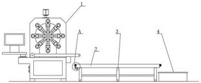
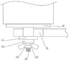
Referring to fig. 1 to 5, the present invention provides a technical solution: a full-automatic production line special for producing a torsion spring comprises a torsion spring machine 1, a chain plate conveyor 2, supporting legs 3 and a material receiving box 4, wherein the chain plate conveyor 2 is arranged on one side of the torsion spring machine 1, the bottom of the chain plate conveyor 2 is provided with a plurality of supporting legs 3 for supporting the chain plate conveyor 2, the material receiving box 4 is arranged on the right side of the chain plate conveyor 2, the inner side of the chain plate conveyor 2 is rotatably provided with a conveying belt 5 through a rotating shaft, a chain wheel is fixed on the rotating shaft and is connected with a motor arranged on the inner side of the chain plate conveyor 2 through a chain, the motor is used for automatically conveying the torsion spring processed by the torsion spring machine 1, the bottom of the chain plate conveyor 2 is provided with a cleaning mechanism, the cleaning mechanism comprises two base columns 6 symmetrically fixed on the surface of the bottom of the chain plate conveyor 2, the surfaces of the two base columns 6 are respectively and slidably sleeved with a base sleeve 7, one side of the two base sleeves 7 is respectively fixed with a side seat 8, and one side of each of the two side seats 8 is fixed with an L-shaped supporting plate 9, a cleaning roller 10 is rotatably arranged between the two L-shaped supporting plates 9, the surface of the cleaning roller 10 is provided with cleaning cotton contacted with the conveying belt 5, the cleaning roller 10 comprises an outer roller and an inner roller, the inner roller is rotationally connected with the outer roller through a bearing, and the cleaning cotton is arranged on the surface of the outer roller, so that the outer roller can rotate on the inner roller, thereby avoiding increasing the passing resistance of the conveying belt 5, the inner part of the base column 6 is provided with an inner sliding chute 17, an inner slide block 19 and a spring 20 are arranged inside the inner chute 17, the inner walls of the two sides of the inner chute 17 are both provided with side slideways, and the two side slideways are both provided with connecting blocks 21, the inner slide block 19 is fixed with the base sleeve 7 through the two connecting blocks 21, so that the spring 20 will apply an upward pushing force to the inner slide block 19, the base sleeve 7 and the L-shaped supporting plate 9, so that the cleaning cotton on the cleaning roller 10 is kept attached to the conveying belt 5.
In the embodiment, preferably, the two ends of the inner roller are both provided with T-shaped rods 11, the top ends of the two L-shaped supporting plates 9 are both provided with strip-shaped hanging openings 12 corresponding to the T-shaped rods 11, the two T-shaped rods 11 are respectively embedded into the strip-shaped hanging openings 12 at the top ends of the two L-shaped supporting plates 9, a connecting mechanism is arranged between the T-shaped rods 11 and the L-shaped supporting plates 9, the connecting mechanism comprises a limiting clamping plate 13, a screw 14, a butterfly nut 15 and a limiting rod 16, the screw 14 is fixed on the surface of the L-shaped supporting plate 9, the surface of the screw 14 is rotatably sleeved with the limiting clamping plate 13 and the butterfly nut 15, the butterfly nut 15 is in threaded connection with the screw 14, the surface of the T-shaped rod 11 is fixed with the limiting rod 16, the top end of the limiting clamping plate 13 is provided with a circular hole corresponding to the limiting rod 16, the top end of the limiting clamping plate 13 is sleeved on the limiting rod 16, the bottom end of the limiting clamping plate 13 is provided with a trepan, and the trepan hole is corresponding to the size of the screw 14, so that the cleaning roller 10 can be easily disassembled.
In this embodiment, preferably, an inner guide bar 18 is fixed on the inner side of the inner sliding slot 17, and the inner slider 19 and the spring 20 are both sleeved on the inner guide bar 18 for guiding the inner slider 19 and the spring 20 and preventing the spring 20 from deviating.
In this embodiment, preferably, a slot corresponding to the L-shaped supporting plate 9 is formed in one side of the side seat 8, the bottom end of the L-shaped supporting plate 9 is inserted into the slot, and the L-shaped supporting plate 9 and the side seat 8 are fixed by a bolt.
In this embodiment, preferably, the top end of the base pillar 6 is fixed with a top seat, and the top seat is fixed to the bottom surface of the scraper conveyor 2 by bolts.
The working principle and the using process of the utility model are as follows: when the torsion spring production line is used, the torsion spring machine 1 firstly completes the processing and forming of the torsion spring, the processed and formed torsion spring falls on the top of the chain plate conveyor 2 and is conveyed by the conveying belt 5, and finally falls on the inner side of the material collecting box 4 for collection, so that the production of the torsion spring is completed;
during the operation of the chain plate conveyor 2, the motor on the inner side of the chain plate conveyor 2 drives the chain wheel to rotate through the chain, so that the chain wheel drives the conveying belt 5 to realize the operation, during the operation of the conveying belt 5, the cleaning cotton on the surface of the cleaning roller 10 can wipe and clean the surface of the conveying belt 5, the situation that the conveyed torsion spring is polluted by the dirt and the cutting chips on the surface of the conveying belt 5 is avoided, the product cleanliness of the torsion spring is improved, the inner sliding block 19 is pushed upwards by the spring 20 under the self elastic action, the inner sliding block 19 can drive the base sleeve 7 to move upwards, the base sleeve 7 drives the L-shaped supporting plate 9 and the cleaning roller 10 to move upwards, finally, the cleaning cotton on the surface of the cleaning roller 10 is attached to the conveying belt 5 constantly, the surface cleaning of the conveying belt 5 is realized, and when the cleaning roller 10 needs to be detached for cleaning and replacing, only the butterfly nut 15 needs to be screwed anticlockwise, the butterfly nut 15 is driven to move towards the end part of the screw 14, then the limiting clamping plate 13 is driven to move towards the end part of the screw 14 until the top end of the limiting clamping plate 13 is separated from the limiting rod 16, at the moment, the L-shaped supporting plates 9 can be directly pressed downwards, the L-shaped supporting plates 9 are driven to move downwards, the springs 20 are compressed, meanwhile, the cleaning roller 10 is driven upwards, the T-shaped rod 11 is driven to move out of the strip-shaped hanging opening 12, the cleaning roller 10 can be smoothly detached from the two L-shaped supporting plates 9 for cleaning or replacement, when the cleaning roller 10 is installed subsequently, the two L-shaped supporting plates 9 are pressed downwards, the cleaning roller 10 is pushed into the two L-shaped supporting plates 9, the T-shaped rod 11 is driven to be hung at the bottom end of the strip-shaped hanging opening 12, then the top end of the limiting clamping plate 13 is sleeved on the limiting rod 16, the butterfly nut 15 is screwed down clockwise, and the limiting of the limiting clamping plate 13 on the limiting rod 16 can be completed, and the installation of the cleaning roller 10 is smoothly completed.
Although embodiments of the present invention have been shown and described, it will be appreciated by those skilled in the art that changes, modifications, substitutions and alterations can be made in these embodiments without departing from the principles and spirit of the utility model, the scope of which is defined in the appended claims and their equivalents.
Claims (7)
1. The utility model provides a special full-automatic production line of torsional spring production, includes torsional spring machine (1), chain scraper conveyor (2), props leg (3) and receipts workbin (4), chain scraper conveyor (2) set up the one side in torsional spring machine (1), and the bottom of chain scraper conveyor (2) installs a plurality of legs (3) that prop, receive workbin (4) and set up the right side in chain scraper conveyor (2), conveyor (5), its characterized in that are installed through the pivot rotation to the inboard of chain scraper conveyor (2): the bottom of the chain plate conveyor (2) is provided with a cleaning mechanism, the cleaning mechanism comprises two symmetrical foundation columns (6) which are fixed on the surface of the bottom of the chain plate conveyor (2), the surface of each foundation column (6) is provided with a base sleeve (7) in a sliding manner, one side of each base sleeve (7) is provided with a side seat (8), one side of each side seat (8) is provided with an L-shaped supporting plate (9), a cleaning roller (10) is rotatably arranged between the two L-shaped supporting plates (9), cleaning cotton contacted with a conveying belt (5) is arranged on the surface of the cleaning roller (10), the cleaning roller (10) comprises an outer roller and an inner roller, the inner roller is rotatably connected with the outer roller through a bearing, the cleaning cotton is arranged on the surface of the outer roller, an inner chute (17) is formed in the base column (6), an inner sliding block (19) and a spring (20) are arranged in the inner sliding chute (17), side slide has all been seted up to the both sides inner wall of interior spout (17), and two all be provided with connecting block (21) in the side slide, interior slider (19) are fixed with base cover (7) through two connecting block (21).
2. The full-automatic production line special for producing the torsion spring according to claim 1, is characterized in that: the both ends of interior roller all are provided with T shape pole (11), two the strip is hung mouthful (12), two have all been seted up on the top of L shape fagging (9) T shape pole (11) are embedded into respectively in strip string mouthful (12) on two L shape fagging (9) tops, be equipped with coupling mechanism between T shape pole (11) and L shape fagging (9).
3. The full-automatic production line special for producing the torsion spring according to claim 2, is characterized in that: the connecting mechanism comprises a limiting clamping plate (13), a screw (14), a butterfly nut (15) and a limiting rod (16), the screw (14) is fixed on the surface of the L-shaped supporting plate (9), the surface of the screw (14) is rotatably sleeved with the limiting clamping plate (13) and the butterfly nut (15), the butterfly nut (15) is in threaded connection with the screw (14), the limiting rod (16) is fixed on the surface of the T-shaped rod (11), a round hole is formed in the top end of the limiting clamping plate (13), and the top end of the limiting clamping plate (13) is sleeved on the limiting rod (16).
4. The full-automatic production line special for producing the torsion spring according to claim 3, is characterized in that: the bottom end of the limiting clamping plate (13) is provided with a trepan boring, and the size of the trepan boring corresponds to that of the screw rod (14).
5. The full-automatic production line special for producing the torsion spring according to claim 1, is characterized in that: an inner guide rod (18) is fixed on the inner side of the inner sliding groove (17), and the inner sliding block (19) and the spring (20) are sleeved on the inner guide rod (18).
6. The full-automatic production line special for producing the torsion spring according to claim 1, is characterized in that: the slot has been seted up to one side of side seat (8), the bottom of L shape fagging (9) inserts to the slot in, and passes through the bolt fastening between L shape fagging (9) and side seat (8).
7. The full-automatic production line special for producing the torsion spring according to claim 1, is characterized in that: and a top seat is fixed at the top end of the foundation column (6), and the top seat is fixed on the bottom surface of the chain plate conveyor (2) through a bolt.
Priority Applications (1)
| Application Number | Priority Date | Filing Date | Title |
|---|---|---|---|
| CN202220028265.2U CN216710643U (en) | 2022-01-07 | 2022-01-07 | Special full-automatic production line for producing torsional springs |
Applications Claiming Priority (1)
| Application Number | Priority Date | Filing Date | Title |
|---|---|---|---|
| CN202220028265.2U CN216710643U (en) | 2022-01-07 | 2022-01-07 | Special full-automatic production line for producing torsional springs |
Publications (1)
| Publication Number | Publication Date |
|---|---|
| CN216710643U true CN216710643U (en) | 2022-06-10 |
Family
ID=81888673
Family Applications (1)
| Application Number | Title | Priority Date | Filing Date |
|---|---|---|---|
| CN202220028265.2U Active CN216710643U (en) | 2022-01-07 | 2022-01-07 | Special full-automatic production line for producing torsional springs |
Country Status (1)
| Country | Link |
|---|---|
| CN (1) | CN216710643U (en) |
-
2022
- 2022-01-07 CN CN202220028265.2U patent/CN216710643U/en active Active
Similar Documents
| Publication | Publication Date | Title |
|---|---|---|
| CN211940344U (en) | Sheet metal surface treatment equipment | |
| CN109013582B (en) | Automatic PVC pipe recovery system and automatic PVC pipe treatment process thereof | |
| CN211161098U (en) | Glass surface cleaning device | |
| CN216710643U (en) | Special full-automatic production line for producing torsional springs | |
| CN203725410U (en) | Compound cleaning machine of track pin bush | |
| CN113601367B (en) | Old and useless steel pipe material rust cleaning device for construction | |
| CN109420539A (en) | A kind of waste ceramic crushing device | |
| CN219669564U (en) | Lifting machine convenient to installation | |
| CN207014671U (en) | A kind of safety-type cleaning device of screw in injection molding machine | |
| CN213058995U (en) | Automatic cleaning device for plate blank conveying belt of oriented strand board | |
| CN2835260Y (en) | Automatic pressure-disengaging machine for residual anode in aluminum electrolysis | |
| CN217284380U (en) | Mutation breeding machine for high-quality seed breeding | |
| CN207138345U (en) | A kind of copper gang chain cleaning inside device | |
| CN218035783U (en) | Novel unpowered sampling device | |
| CN213170568U (en) | Seamless fabric manufacturing equipment | |
| CN208427431U (en) | Casting automatic flushing device | |
| CN219949967U (en) | Special conveying equipment for clothing processing production line | |
| CN106733884A (en) | A kind of Chinese medicine Quick cleaning device | |
| CN216334872U (en) | Belt feeding system with dust removal structure | |
| CN217512773U (en) | Carbon element structure steel wire cuts device | |
| CN210414115U (en) | Fixed frock is used in processing of five metals casting pipe fitting | |
| CN218889215U (en) | Continuous tea twisting device | |
| CN219442588U (en) | Cleaning device for door and window processing | |
| CN217802378U (en) | Slurry recovery device | |
| CN218610545U (en) | Press powder collection device |
Legal Events
| Date | Code | Title | Description |
|---|---|---|---|
| GR01 | Patent grant | ||
| GR01 | Patent grant |