CN216709679U - Horizontal packaging machine - Google Patents
Horizontal packaging machine Download PDFInfo
- Publication number
- CN216709679U CN216709679U CN202220197359.2U CN202220197359U CN216709679U CN 216709679 U CN216709679 U CN 216709679U CN 202220197359 U CN202220197359 U CN 202220197359U CN 216709679 U CN216709679 U CN 216709679U
- Authority
- CN
- China
- Prior art keywords
- bag
- arc
- station
- shaped plate
- conveying belt
- Prior art date
- Legal status (The legal status is an assumption and is not a legal conclusion. Google has not performed a legal analysis and makes no representation as to the accuracy of the status listed.)
- Active
Links
Images


Abstract
The utility model discloses a horizontal packaging machine which comprises a turntable, a bag opening and closing mechanism, a feeding mechanism and a sealing mechanism, wherein the turntable is provided with a plurality of bag placing areas, and a bag feeding station, a feeding station and a sealing station are sequentially arranged in the circumferential direction of the turntable; the bag opening and closing mechanism comprises an upper material sucking part and a lower material sucking part which can be lifted up and down, and the upper material sucking part and the lower material sucking part are arranged at the feed end of the bag placing area; the feeding mechanism comprises a material conveying belt and a material pushing part, the material conveying belt is provided with a discharge port, and the discharge port is connected with the turntable; the sealing mechanism is arranged at the sealing station. The bag body is horizontal at last bag station and arranges the bag district of putting of carousel in to open the sack through sack opening and shutting mechanism, when the carousel sent the bag body to reinforced station, it was internal to push away the material propelling movement of material conveyer belt upper discharging station to the bag, and then the part is closed with the sack to the opening part that opens and shuts, and the carousel then sends the bag body to the involution station with the sack involution, so accomplish the packing.
Description
Technical Field
The utility model relates to an improved invention of a horizontal packaging machine.
Background
Paper bag packaging or film packaging can be used for food packaging, such as bread, nuts and the like, the bottom of the packaging bag is sealed, the bag opening is open, materials enter from the bag opening, and the bag opening is sealed after packaging is completed. At present, the material is gone into the bag and is separately processed with the sack involution, and the sack of wrapping bag adopts the manual work to overlap it outside the support frame, forms square pan feeding mouth, and the material is gone into the bag after, with wrapping bag propelling movement to involution machine again on, with the sack involution, what the adoption was semi-automatic packing, what especially go up bag and sack and open the adoption is manual operation, has the health potential safety hazard, and manual operation is with low costs in efficiency moreover.
Disclosure of Invention
In view of the technical problems in the background art, the technical problem to be solved by the present invention is to provide a full-automatic horizontal packaging machine, which can realize automatic packaging and has good packaging effect and quality.
In order to solve the technical problems, the utility model adopts the following technical scheme: this kind of horizontal packagine machine, its characterized in that: comprises that
The rotary table is provided with a plurality of bag placing areas, the bag placing areas are uniformly arranged along the circumferential direction, and a bag feeding station, a feeding station and a sealing station are sequentially arranged in the circumferential direction of the rotary table;
the bag opening and closing mechanism comprises an upper material sucking part and a lower material sucking part which can be lifted up and down, and the upper material sucking part and the lower material sucking part are arranged at the feed end of the bag placing area;
the feeding mechanism comprises a material conveying belt and a pushing part, the material conveying belt is provided with a discharge port, and the discharge port is connected with the rotary table;
and the sealing mechanism is arranged at the sealing station.
The carousel rotates, put the bag district on the carousel and pass through in proper order and go up the bag station, reinforced station, involution station and output station, the bag body is the horizontal bag district of putting of placing in the carousel at last bag station, and open the sack through sack opening and shutting mechanism, when the carousel sent the bag body to reinforced station, the material propelling movement of ejection of compact station was gone up to the material conveyer belt to the propelling movement of propelling movement spare was internal to the bag, then the opening part of opening and shutting closed the sack, the carousel then sent the bag body to the involution station with the sack involution, so accomplish the packing.
Preferably, the lower end of the rotary table is provided with an arc-shaped plate, the arc-shaped plate is arranged on the rack, and the lower surface of the arc-shaped plate is an arc-shaped surface;
the upper material sucking part is installed on the lifting rod, the lower end of the lifting rod penetrates through the turntable and is provided with an upper rotating wheel, the upper rotating wheel is in press fit with the arc-shaped surface, and the upper rotating wheel moves on the arc-shaped surface when the turntable rotates. The upper material suction part adopts mechanical lifting, so that the stability is better.
Preferably, the lowest point of the arc-shaped plate is arranged at the bag feeding station, the arc-shaped plate is connected with a driving piece for driving the arc-shaped plate to lift, and the driving piece is arranged on the rack.
Preferably, the turntable is connected with one end of a tension spring, and the other end of the tension spring is connected with the lower end of the lifting rod; the lower end of the lifting rod is provided with a limiting block, the limiting block is arranged below the turntable, and the limiting block is movably arranged on the lifting rod; the height of the arc-shaped plate on the rack can be adjusted. The pulling force of extension spring makes the lifter rise all the time, like this, goes up the runner can with the arcwall face pressfitting on the arc, blocks the stopper contact until the carousel, and the lifter no longer rises, can also adjust the height that the lifter rose according to the demand to inhale the highest position after the material spare shifts on adjusting, and through the height of adjusting the arc, inhale the lowest position that the material spare shifted down on adjusting.
Preferably, the bag feeding station is provided with a bag feeding mechanism, and the bag feeding mechanism comprises
The conveying component comprises a bag body conveying belt and a front baffle;
and the transfer component comprises a material sucking part which can be lifted up and down and a transmission assembly which drives the material sucking part to move between the bag taking station and the bag placing area of the turntable.
Preferably, the bag body conveying belt comprises an upper conveying belt and a lower conveying belt, and the upper conveying belt inclines downwards along the bag body conveying direction; the upper conveying belt and the lower conveying belt are arranged in a transverse staggered mode, and the feeding portion at the front end of the upper conveying belt is not higher than the lower conveying belt. Go up the conveyer belt and form the material chamber that has the contained angle with lower conveyer belt, the bag body then is overlapping and getting into the material chamber, and preceding bag body is taken in the top of the back bag body, and the material that gets into is less more close to the front end of last conveyer belt, and last conveyer belt and lower conveyer belt closed department then only a bag body gets into, so go up the conveyer belt and send out a bag body at every turn with lower conveyer belt.
As preferred, reinforced mechanism is still including propping a bag spare, prop a bag spare and set up between discharge gate and carousel, prop a bag spare and divide into a left side and prop a bag spare on the right side, prop a bag spare on the left side and prop a bag spare on the right side and can pass in and out the feed end, it radially removes to push away the material spare relatively to the carousel. The bag opening piece plays a supporting role, the position of the bag opening is fixed, and the bag opening is kept in an open state, so that materials can smoothly enter the bag body.
Preferably, be equipped with between reinforced station and the involution station and close a bag station, it is equipped with a bag mechanism to close a bag station, close a bag mechanism including managing a bag part, managing a bag part including left picture peg and right picture peg, the two can radially pass in and out close a bag district of putting of a bag station, and the two can be in opposite directions or reverse movement.
Aiming at the M-shaped bag body, when the bag is closed, the left inserting plate and the right inserting plate firstly arrange the bag, so that the side surface of the M-shaped bag body is inwards folded along a folding line, two sides of the bag opening are M-shaped, the upper material absorbing part and the lower material absorbing part respectively absorb the upper bag surface and the lower bag surface of the bag body and then move up and down oppositely, the bag opening is closed and is restored to a closed state, the sealed bag opening is very flat, the sealing is firm, and the packaging quality is improved.
Preferably, an upper arc-shaped plate and a lower arc-shaped plate are arranged below the turntable, the lower surface of the upper arc-shaped plate is a first curved surface, the upper surface of the lower arc-shaped plate is a second curved surface, the upper arc-shaped plate and the lower arc-shaped plate move along an arc-shaped guide rail, and the arc-shaped guide rail is installed on the rack;
the upper material sucking part is arranged on a lifting rod, the lower end of the lifting rod penetrates through the turntable and is provided with an upper rotating wheel, and the upper rotating wheel is pressed with the first curved surface;
the lower material sucking part is installed on the lifting seat, a lower rotating wheel is installed on the lifting seat, and the lower rotating wheel is in press fit with the second curved surface. At a bag closing station, the upper arc-shaped plate and the lower arc-shaped plate move along the arc-shaped guide rail, the upper rotating wheel enters the first curved surface to enable the upper material sucking part to move downwards, the lower rotating wheel enters the second curved surface to enable the lower material sucking part to move upwards, and the upper material sucking part and the lower material sucking part move in opposite directions to close a bag opening; compared with the lifting stability of the upper and lower material absorbing parts driven by the cylinder, the lifting device is better in lifting stability and lower in cost.
Preferably, a finished product output station is arranged between the bag feeding station and the sealing station, a finished product output mechanism is arranged at the finished product output station, and the finished product output mechanism comprises a finished product output channel and a material clamping piece which moves radially relative to the rotary table. After the packaging is finished, the bag opening is clamped and moved radially by the material clamping piece and sent to a finished product output channel.
Drawings
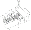
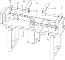
FIG. 1 is a schematic structural diagram of the present invention.
Fig. 2 is a schematic view 1 of the bag feeding mechanism of the present invention.
Fig. 3 is a schematic view 2 of the bag feeding mechanism of the present invention.
Fig. 4 is a schematic view of the feeding mechanism of the present invention.
FIG. 5 is a schematic view of the bag closing mechanism of the present invention.
Fig. 6 is a schematic view of the sealing mechanism of the present invention.
Fig. 7 is a schematic view of the product output mechanism of the present invention.
FIG. 8 is a schematic view of the present invention showing the abduction of the bag opening device.
Fig. 9 is a schematic view of the bag opening member of the present invention when sucking the bag.
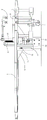
FIG. 10 is a schematic view of the upper suction member of the present invention.
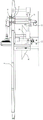
FIG. 11 is a schematic view of the lower suction member of the present invention.
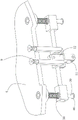
Fig. 12 is a schematic view 1 of an upper arcuate plate and a lower arcuate plate of the present invention.
Fig. 13 is a schematic view 2 of the upper and lower arcuate plates of the present invention.
Detailed Description
The following describes details and operational principles of embodiments and examples of the present invention with reference to the drawings. This kind of horizontal packagine machine opens and shuts 47, feeding mechanism 2 and involution mechanism 5 including carousel 4, sack, carousel 4 is equipped with a plurality of and puts bag district 13, put the bag district and evenly set up along the circumferencial direction, be provided with six in the picture and put bag district 13, the circumferencial direction of carousel is equipped with bag-feeding station 61 in proper order, feeds in raw material station 62, closes bag station 63, involution station 64, output station 65 and vacancy, can set up the quantity setting of putting bag district 13 and processing station according to the demand. Put bag district 13 and be equipped with left limiting plate 23 and right limiting plate 24, the interval between left limiting plate and the right limiting plate matches with the width of the bag body, and left limiting plate and right limiting plate form and put the bag region, carry on spacingly to the bag body, the position of the accurate bag body, even when the carousel rotated, the bag body can not shift yet. Left side limiting plate and right limiting plate movable mounting are on the carousel, according to the width of the bag body and the position of reinforced position adjustment left limiting plate and right limiting plate and the interval of the two promptly, in the figure, seted up rectangular mounting groove 39 on left limiting plate and the right limiting plate, the mounting hole has then been seted up on carousel 4, after adjusting the position of left limiting plate and right limiting plate, locking bolt passes the mounting groove and the mounting hole is connected with the nut, fixes left and right limiting plate on the carousel. The bag opening and closing mechanism 47 comprises an upper material sucking part 8 and a lower material sucking part 9 which can be lifted up and down, the upper material sucking part and the lower material sucking part are arranged at the feed end of the bag placing area, and the number of the bag opening and closing mechanisms is consistent with that of the bag placing area; the feeding mechanism 2 comprises a material conveying belt 51 and a pushing piece 52, the material conveying belt is provided with a discharge port, and the discharge port is connected with the rotary table 4; sealing mechanism 5 sets up at involution station 64, and corresponding involution structure can be selected according to the product characteristic to sealing mechanism, for example, the bag body can adopt the heat-seal for film or drench the membrane material, makes the sack involution through the heating system, if for the bag body is the non-woven fabrics, then can adopt ultrasonic bonding, if can adopt the mode involution of rubber coating and pressfitting for the container bag, the film bag is used as the example in this embodiment, sealing mechanism is including the last hot sealing plate 56 and the lower hot sealing plate 57 of looks pressfitting. At an upper bag station 61, the packaging bags are placed in a bag placing area 13 of a turntable, the packaging bags are placed horizontally, bag openings face outwards, a lower material sucking part 9 sucks the lower bag surface of the bag body, an upper material sucking part 8 moves downwards to suck the upper bag surface of the bag body, then the upper material sucking part moves upwards to open the bag openings, the turntable 4 conveys the bag body to a feeding station 62, a material pushing part 52 pushes materials of a material conveying belt to move towards a discharge opening until the materials enter the bag body on the turntable 4, the upper material sucking part 8 moves downwards and the bag openings are closed, the lower material sucking part can be lifted or not lifted, the lower material sucking part 9 can be lifted or lifted, and for large-capacity bag bodies or M-shaped bag bodies, the upper material sucking part moves downwards and the upper material sucking part moves upwards when the bags are combined, so that the bag opening edges can be aligned up and down, and the packaging effect is better; after feeding, the turntable 4 continues to rotate, the bag body after feeding is sent to the sealing station 63, and the upper heat sealing plate 56 and the lower heat sealing plate 57 are pressed to seal the bag mouth, so that packaging is completed.
The upper material sucking part 8 can be driven to lift by power parts such as an air cylinder or a motor, and in order to save cost, the upper material sucking part can also be lifted by adopting a mechanical structure, an arc-shaped plate 30 is arranged at the lower end of the rotary table 4, the arc-shaped plate is arranged on the rack 10 and is vertically arranged, and the lower surface of the arc-shaped plate is an arc-shaped surface 31; the upper material sucking part 8 is arranged on a lifting rod 36, the lower end of the lifting rod penetrates through the turntable 4 and is provided with an upper rotating wheel 35, the upper rotating wheel is pressed with the arc-shaped surface 31, the upper rotating wheel moves on the arc-shaped surface when the turntable 4 rotates, the lifting rod 36 moves downwards when the upper rotating wheel moves to the low point of the arc-shaped surface, the upper material sucking part moves downwards along with the upper rotating wheel, and the lifting rod rises and the upper material sucking part also rises along with the upper rotating wheel 35 when the upper rotating wheel moves to the high point of the arc-shaped surface; the turntable 4 rotates intermittently, after the operation is completed at each station, the turntable rotates to convey the bag body to the next station, if the bag feeding speed is higher than the feeding speed, in order to more reasonably utilize the time, the bag feeding station is provided with an upper bag sucking part 8 for downward bag sucking operation, specifically, when the bag is fed, the upper bag sucking part moves upward to give the upper bag abdicating, the bag feeding area is used for placing the bag body in the bag placing area, after the bag is fed, the lower bag sucking part 8 moves downward to suck the upper bag surface of the bag body, the bag sucking part at the bag feeding station has two states, namely an abdicating state after upward movement, a downward material sucking state, the arc-shaped plate 30 is connected with a driving part 34 for driving the arc-shaped plate to ascend and descend, the driving part is installed on the frame, the arc-shaped plate 30 can ascend and descend relative to the turntable, so that the arc-shaped plate has two states, namely a material sucking state after downward movement, and a abdicating state after upward movement, at the bag feeding station 61, when bags are fed, see fig. 8, the driving part drives the arc-shaped plate 30 to move upwards, the lifting rod 36 moves upwards, the upper material sucking part 8 moves upwards and has a certain distance with the turntable, at the moment, the upper rotating wheel 35 is at the lowest position of the arc-shaped surface, after bags are fed, see fig. 9, the driving piece drives the arc-shaped plate 30 to move downwards, the lifting rod moves downwards, the upper material absorbing piece 8 moves downwards to the lowest point to absorb the bag body, then, the turntable 4 rotates, the upper rotating wheel 35 gradually moves to a high position along the arc-shaped surface 31, so that the lifting rod and the upper material sucking part 8 move upwards, so as to gradually open the pocket mouth, and the driving piece 34 drives the arc-shaped plate 30 to move upwards again, so that the arc-shaped plate moves upwards to the yielding state, a certain gap should be formed between the arc-shaped plate in the yielding state and the turntable, the turntable can not rub the arc-shaped plate when rotating, finally, the upper rotating wheel 35 leaves the arc-shaped plate, and the bag opening is in a fully opened state. The arrangement position of the arc-shaped plate is set according to requirements, if the upper material sucking part only goes up and down through the arc-shaped plate, when the bag is fed at a bag feeding station 61, the upper rotating wheel is arranged at the high position of the arc-shaped surface, after the bag is fed, the upper rotating wheel rotates along with the turntable, the upper material sucking part moves downwards to suck materials, then the upper rotating wheel moves towards the high point step by step to realize bag opening, when the bag body is conveyed to the feeding station by the turntable, the bag opening is in an open state, feeding operation can be directly carried out at the moment, therefore, the lowest point of the arc-shaped plate is between the bag feeding station 61 and the feeding station 62, the highest point of the arc-shaped plate 30 is better at the feeding station or before entering the feeding station, and the upper material sucking part at the feeding station is at the highest point; if the upper suction part is lifted through the arc-shaped plate and the driving part for driving the arc-shaped plate to lift, the lowest point of the arc-shaped plate is at the bag feeding station, the upper suction part moves downwards to the lowest point at the bag feeding station to adsorb the bag body, and similarly, the highest point of the arc-shaped plate is preferably at the feeding station or before entering the feeding station. For the messenger go up the runner can with the arcwall face pressfitting all the time, will give upward power of runner, the carousel is connected with the one end of an extension spring 37, the other end of extension spring is connected with the lower extreme of lifter 36, and the extension spring gives the lifter and goes up the ascending power of runner, goes up the runner like this when the arc, then all the time with the arcwall face pressfitting. The lower end of the lifting rod is provided with a limiting block 49, the limiting block is arranged below the turntable, when the turntable rotates and the upper rotating wheel moves from a low point to a high point of the arc-shaped surface, the lifting rod is lifted by the tensile force of the tension spring, the turntable blocks the limiting block, the lifting rod does not lift any more, the upper material suction part is in the highest state, and the opening of the bag opening is also in an open state, in the figure, an upper limiting block 48 is arranged below the turntable, and when the limiting block 49 is in contact with the upper limiting block 48, the lifting rod cannot lift; the sizes of the bag bodies are different, the opening heights are also different, in order to be suitable for different bag bodies, the rising height of the upper material sucking part needs to be adjusted, the limiting block is movably arranged on the lifting rod, the position of the limiting block on the lifting rod is adjusted, the limiting block can be fixed by a locking bolt after the position of the limiting block on the lifting rod is determined, the lower the position of the limiting block is, the longer the rising stroke of the lifting rod is, the higher the rising height of the upper material sucking part is, and conversely, the higher the position of the limiting block is, the shorter the rising stroke of the lifting rod is, and the lower the rising height of the upper material sucking part is; similarly, the upper limit block 48 can be movably arranged on the rotating disc 4. After the ascending peak of the upper suction part 8 is adjusted, the corresponding adjustment is needed to be performed to the lowest point after the lower suction part 8 moves downwards, the height of the arc-shaped plate 30 on the rack can be adjusted, the height of the arc-shaped plate on the rack 10 is adjusted, the lowest point of the upper suction part 8 moving downwards is adjusted, namely the height of the upper suction part sucking a bag, a vertically arranged guide part can be arranged on the rack, the arc-shaped plate goes up and down along the guide part, the arc-shaped plate is fixed by a locking part after the height of the arc-shaped plate is determined, the height of the arc-shaped plate can also be adjusted by adopting a screw rod mechanism, if the arc-shaped plate does not go up and down through a driving part, the installation height of the arc-shaped plate on the rack can be adjusted, and if the arc-shaped plate goes up and down through the driving part, the installation height of the driving part 34 on the rack can be adjusted.
The feeding mechanism 2 further comprises a bag supporting piece 53, the bag supporting piece is arranged on one side of the discharge hole of the material conveying belt 51, namely between the discharge hole of the material conveying belt and the rotary table, the pushing piece 52 is arranged on the other side of the discharge hole of the material conveying belt, and the pushing piece is connected with a driving assembly for driving the pushing piece to move radially relative to the rotary table, so that materials on the material conveying belt can be directly pushed into a bag body of a feeding station, and the pushing piece 52 can adopt a pushing plate; the bag supporting piece is divided into a left bag supporting piece and a right bag supporting piece, one end of the left bag supporting piece and one end of the right bag supporting piece are installation ends, the other end of the left bag supporting piece and the other end of the right bag supporting piece are bag supporting ends, the bag supporting ends of the left bag supporting piece and the right bag supporting piece can enter and exit from the feeding ends, the left bag supporting piece and the right bag supporting piece can support bag plates, an upper bag supporting plate and a lower bag supporting plate in small specifications are arranged on the left side and the right side in the drawing, a large bag supporting plate can also be adopted, the bag supporting pieces have a supporting function, when the bag body is conveyed to the feeding station 2 by the turntable 4, the upper suction piece 8 adsorbs and moves upwards to enable the bag mouth to be opened, the bag supporting ends of the bag supporting pieces enter the bag body at the moment, the opened bag mouth is supported, and the bag mouth is kept in an open state, so that materials can smoothly enter the bag body; it is good to prop a bag spare and get into the feed end with the wobbling mode, the installation end is installed in pivot 54, the pivot is rotated and is installed in frame 10, cylinder or motor drive can be adopted in the pivot, under the conventional state, the bag end that props of a left side bag spare and right side bag spare draws close, and when reinforced, pivot 54 rotates, and the bag end that props of a left side bag spare and right side bag spare is relative reverse swing, gets into in the bag body, and the two is opened and is formed material passageway 50, for propping a bag state in the picture, it removes to the sack direction to push away material spare 52, promotes the material on the material conveyer belt 7, and the material gets into in the bag body through the material passageway, and after reinforced the completion, pushes away material spare and retreat the reduction, and pivot 54 reverse rotation, the bag end that props of a left side bag spare and right side bag spare is then the swing in opposite directions, leaves the bag body, and the two draws close. The pan feeding end of bag spare and the right branch bag spare that props on a left side inclines to the outside, and the width of the pan feeding end of material passageway is great, more does benefit to the material and gets into in the bag body. Be equipped with a plurality of baffle 55 on the material conveyer belt 51, adjacent baffle forms the material chamber, and the baffle separates the material each other, avoids the material to take place to shift on the material conveyer belt moreover, fixes a position accurately, does benefit to reinforced. The material pushing component 52 can be driven by a cylinder, in this embodiment, the driving component comprises a transmission belt and a guide rail, the transmission belt and the guide rail are radially arranged relative to the turntable, the transmission belt is arranged on the transmission wheel, the transmission wheel is connected with the motor, the guide rail is provided with a sliding block, the material pushing component is connected with the sliding block and the transmission belt, the motor is started, the transmission wheel rotates, and the transmission belt drives the material pushing component to move along the guide rail to push the material into the bag body.
The bag feeding station 61 is provided with a bag feeding mechanism 1 which comprises a conveying part and a transfer part, wherein the conveying part comprises a bag body conveying belt and a front baffle plate 27; the transfer component comprises a material absorbing part 7 which can be lifted up and down and a transmission component which drives the material absorbing part to move between the bag taking station and the bag placing area of the turntable; the bag body conveying belt conveys the bag bodies forwards until the front baffle 27 blocks the bag bodies which move forwards to enable the bag bodies to stay at the bag taking station, the material sucking part 7 of the transfer part moves to the upper part of the bag bodies, the bag bodies are adsorbed by moving downwards, then the material sucking part moves upwards and moves to the bag placing area of the bag placing station, the material sucking part stops sucking air, and the bag bodies fall on the bag placing area to realize automatic bag feeding. Install sensor 28 that targets in place on the preceding baffle, the sensor that targets in place can photoelectric sensor, proximity switch etc. the sensor that targets in place, conveying part and pass on the part all are connected with the controller electricity, and when the bag body when reaching and get a bag station, the sensor that targets in place detects the material to give the controller with information transmission, give conveying part and pass on the part by controller send instruction, conveying part's bag body conveyer belt pause pay-off, change by inhaling the material piece and carry out the pay-off, realize automated control, improve the stability and the precision of pay-off. Inhale lift and transmission assembly of material piece 7 can adopt cylinder or motor to combine screw mechanism, link mechanism, cam etc, the cylinder is adopted in the lift of inhaling material piece 7, transmission assembly is including rack 20, gear 22 and linear guide, linear guide vertically installs in the frame, the last slip of linear guide is provided with slider 21, the slider with inhale the material piece and install on rack 20, rack and linear guide parallel arrangement, the rack meshes with gear 22, the gear is connected with its pivoted motor 29 of drive, the motor is installed in the frame, and motor drive gear 22 rotates, makes rack 20 and inhale material piece 7 along linear guide back-and-forth movement, realizes inhaling the material piece and getting the bag station and put the bag and move between the district. The bag conveyor includes an upper conveyor 26 and a lower conveyor 16, the upper conveyor sloping downwardly in the bag conveying direction. Go up the conveyer belt and form the material chamber that has the contained angle with lower conveyer belt, the bag body then is overlapping entering material chamber, and the preceding bag body is taken in the top of the back bag body, and the material that the front end that is close to last conveyer belt 26 gets into more less, goes up conveyer belt 26 and 16 closed departments of lower conveyer belt then only a bag body gets into, can see the bag body off one by one for guaranteeing last conveyer belt and lower conveyer belt, go up conveyer belt and the horizontal dislocation set of lower conveyer belt, the front end pay-off portion of going up the conveyer belt is not higher than lower conveyer belt, and around the last conveyer belt of establishing in driven wheel 15 below not being higher than lower conveyer belt promptly, like this, even to the thin bag body, go up conveyer belt 26 and lower conveyer belt 16 and also can push down the bag body to see the bag body out. The upper conveying belt is arranged on the driving wheel 25 and the driven wheel 15, the driving wheel is connected with the motor, the driven wheel 15 is rotatably arranged on the swing arm 43, the swing arm is arranged on the mounting frame, the swing arm can be fixed on the mounting frame through a locking bolt, the height of the driven wheel can be adjusted through the swing arm during adjustment, so that the position and the angle of the upper conveying belt relative to the lower conveying belt are adjusted, feeding is stable, and after the adjustment is finished, the locking bolt can fix the swing arm on the mounting frame; the motor and the mounting rack can also be arranged on the rack 10 in a longitudinal sliding mode, the position of the upper conveying belt is adjusted according to the length of the bag body, if the bag body is long, the upper conveying belt moves backwards relative to the conveying direction, and if the bag body is short, the upper conveying belt moves forwards.
The packaging bag comprises a flat bag and an M-shaped bag, wherein two sides of the flat bag are sealed and are side edges, the M-shaped bag body is provided with a side surface after being unfolded, and when the M-shaped bag body is folded, the side surface of the bag body is inwards folded along a central line to form an M shape. The structure that the upper material sucking part downwards moves to suck materials and upwards moves to open the bag can be applied to bag closing after feeding, but after the M-shaped packaging bag is filled with materials, the side surface of the bag body is opened, the bag opening part is also in an opening state, the bag closing is realized in a mode that the lower material sucking part is not moved and the upper material sucking part downwards moves, the problems of uneven bag opening, unstable sealing, leakage sealing and the like can occur, therefore, the upper material sucking part downwards moves by half and the lower material sucking part upwards moves by half during bag closing, so that different structures are needed for bag closing, and in order to restore the M-shaped bag opening after bag closing and align the bag opening upwards and downwards, the bag closing station 63 is provided with the bag closing mechanism 3 which comprises a bag arranging part which comprises a left inserting plate 68 and a right inserting plate 66 which can radially enter and exit the bag placing area 13 of the bag closing station and can move oppositely or reversely, when the left inserting plate 68 and the right inserting plate 66 move oppositely, the distance between the left inserting plate and the right inserting plate becomes smaller, and the left inserting plate and the right inserting plate are in an opening state when the left inserting plate and the right inserting plate move reversely, so that the left inserting plate 68 and the right inserting plate 66 cannot collide with a bag body when entering a bag closing station; when the bag is closed, the left inserting plate and the right inserting plate are in an opening state, the distance between the left inserting plate and the right inserting plate is large, the left inserting plate and the right inserting plate move towards the bag body direction and enter a bag placing area, then the left inserting plate and the right inserting plate move towards the left and right, namely the left inserting plate moves towards the right, the right inserting plate moves towards the left and right, the right inserting plate inserts the right inserting plate into the side surface of the bag body to enable the side surface of the bag body to gradually fold towards the bag opening from the bottom, the upper material sucking piece 8 and the lower material sucking piece 9 suck the bag and move towards the left and right, namely the upper material sucking piece sucks the bag opening of the upper bag surface of the bag body to move downwards, the lower material sucking piece sucks the bag opening of the bag surface of the bag body to move upwards, the bag opening is gradually closed and is restored to an M shape, the bag is conveyed to a sealing station for heat sealing after the bag is closed, and the bag opening after the bag is very flat, and the sealing is firm, improve the packaging quality. In the embodiment, the left inserting plate 68 and the right inserting plate 66 are mounted on a left sliding seat 70 and a right sliding seat 71, the left sliding seat and the right sliding seat are slidably arranged on a guide part 72, the guide part in the figure is a guide rod, and a linear guide rail, a guide groove and the like can also be adopted, the guide part is transversely arranged on a moving seat 75, the moving seat is connected with a driving part for driving the moving seat to radially move relative to the rotary table, and the driving part adopts an air cylinder; the left sliding block 70 is hinged to one end of a left connecting rod 73, the right sliding block 71 is hinged to one end of a right connecting rod 76, the other end of the left connecting rod and the other end of the right connecting rod are respectively hinged to two ends of a rotating rod 74, the rotating rod is rotatably arranged on the movable seat and is connected with a motor, the motor drives the rotating rod 74 to rotate forward, the left sliding seat 70 and the right sliding seat 71 move oppositely along the guide rod, and the motor drives the rotating rod to rotate reversely, so that the left sliding seat and the right sliding seat move reversely along the guide rod; the air cylinder stretches out and then drives the moving seat to move towards the bag body, so that the left inserting plate and the right inserting plate enter the bag placing area, and the air cylinder retracts to drive the moving seat to retreat, so that the left inserting plate and the right inserting plate leave the bag placing area. The right side of the insertion end 69 of the left inserting plate and the left side of the insertion end of the right inserting plate are arc-shaped, and the left inserting plate and the right inserting plate are in contact with the bag body through arc surfaces, so that the bag body is prevented from being scratched; left picture peg and right picture peg movable mounting are on left slide and right slide, and the height of left picture peg and right picture peg is adjusted according to the height of the bag body and the crease line of the side of the bag body, make left picture peg and right picture peg male height and crease line be close, and in the picture, left picture peg and right picture peg extend and have vertical mounting panel, vertical installation elongated slot 67 has been seted up on the mounting panel, after adjusting the height of left picture peg or right picture peg, the fitting pin passes the installation elongated slot and is connected with left slide or right slide, and is fixed with left and right picture peg. The following describes a mechanical structure for driving the upper material sucking part and the lower material sucking part to lift, an upper arc plate 77 and a lower arc plate 79 are further arranged below the turntable 4, the lower surface of the upper arc plate is a first curved surface 78, the upper surface of the lower arc surface is a second curved surface 80, the upper arc plate and the lower arc plate move along an arc-shaped guide rail 84, and the arc-shaped guide rail is mounted on the frame; the lower material sucking part is installed on the lifting seat, the lower rotating wheel is in press fit with the second curved surface, and the upper rotating wheel is in press fit with the first curved surface. At the bag closing station, the upper arc-shaped plate 78 and the lower arc-shaped plate 79 move along the arc-shaped guide rail 84, the upper rotating wheel enters the first curved surface, the first curved surface forces the lifting rod to move downwards, so that the upper material sucking part moves downwards, the lower rotating wheel enters the second curved surface, the second curved surface forces the lifting seat to move upwards, so that the lower material sucking part moves upwards, and the upper material sucking part and the lower material sucking part move oppositely to close the bag opening. The first curved surface comprises an ascending section 88, a stable section 89 and a falling section 90 which are sequentially arranged along the rotating direction of the turntable, the upper rotating wheel 35 gradually enters the stable section from the ascending section and then leaves from the falling section, the ascending section and the falling section respectively enable the upper material absorbing part 8 to gradually descend and ascend, the stable section enables the upper material absorbing part to keep the descending state, the second curved surface 80 can also be divided into the ascending section, the stable section enables the lower rotating wheel to keep the ascending state, the upper material absorbing part and the lower material absorbing part enable the bag mouth of the bag body to keep the closed state, when the turntable rotates, the upper rotating wheel and the lower rotating wheel can still move on the stable section of the first curved surface and the second curved surface, the bag mouth can be always kept closed until the bag mouth enters the sealing station, and in the rotating process of the turntable, the upper arc-shaped plate and the lower arc-shaped plate reversely move and reset, giving way to the bag closing component in the previous process. After the sealing is finished, when the rotary table continues to rotate, the upper rotating wheel and the lower rotating wheel enter the falling section, the upper material absorbing part and the lower material absorbing part stop absorbing materials and respectively move up or down to be separated from the bag body. In the figure, the second curved surface 80 only has an ascending section and a flat section, the lower arc-shaped plate 79 is connected with the second arc-shaped plate 98, the upper surface of the second arc-shaped plate is a third curved surface 99, the third curved surface has a flat section and a falling section, the flat section of the second curved surface 80 and the flat section of the third curved surface 99 are equal in height, the lower arc-shaped plate and the second arc-shaped plate form an arc-shaped plate with an ascending section, a flat section and a falling section, the lower rotating wheel 11 can directly enter the flat section of the third curved surface from the flat section of the second curved surface and finally leave from the falling section of the third curved surface, in the process that the rotating disc rotates to drive the bag body to enter the next station, the second arc-shaped plate 98 can make the lower rotating wheel move to the next station, so that the lower rotating wheel 11 keeps the ascending state until the heat-sealing station, that is, the bag body has the bag mouth kept in the closed state by the upper material sucking member 8 and the lower material sucking member 9 to enter the heat-sealing station 64, the falling section is arranged between the heat-sealing station and the output station, and after the bag mouth is sealed, the upper material absorbing part and the lower material absorbing part respectively ascend and descend to reset, so that the output of finished products is not influenced. The movement of the upper arc-shaped plate and the lower arc-shaped plate along the arc-shaped guide rail can be pushed by external force or driven by a rotating connecting rod, and the like, in the embodiment, the upper arc-shaped plate is installed on the lower arc-shaped plate, the lower arc-shaped plate is arranged on the arc-shaped guide rail 84 in a sliding manner, and the lower arc-shaped plate is connected with a driving assembly for driving the lower arc-shaped plate to move along the arc-shaped guide rail; the driving component comprises a gear 97, an arc rack 96 and a motor for driving the gear to rotate, the gear is engaged with an arc-shaped rack, the arc-shaped rack is arranged on the lower arc-shaped plate 79, the motor drives the gear to rotate, so that the arc rack 96 moves on the arc guide rail 84, which in turn drives the upper arc plate 77 and the lower arc plate 79 to move, the arc-shaped rack, the arc-shaped guide rail and the turntable are concentrically arranged, when the arc-shaped rack moves or the turntable 4 moves, the moving tracks of the upper rotating wheel and the lower rotating wheel relative to the upper arc-shaped plate and the lower arc-shaped plate are consistent, after the bag mouth of the bag body is closed, the rotary table sends the bag body to a sealing station for sealing, at the moment, the upper material absorbing part and the lower material absorbing part are kept in a bag-closing state, therefore, the sealing station can be entered through the stable sections of the first curved surface and the second curved surface, and the three surfaces are concentrically arranged to achieve the effect.
A spring 38 for enabling the lower rotating wheel to move downwards is arranged between the rotary table 4 and the lifting seat 12, the elastic force of the spring pushes the lifting seat to move downwards, so that the lower rotating wheel is in press fit with the second curved surface 80, in the figure, a guide pillar 39 is installed at the lower end of the rotary table, the spring 38 is sleeved outside the guide pillar, the lifting seat is arranged on the guide pillar in a sliding mode, a lower limiting piece 46 is arranged at the bottom of the guide pillar, and the elastic force of the spring enables the lower rotating wheel to be in press fit with the second curved surface 80. Go up to inhale material 8 and only need carry out the action of oscilaltion, rotate at the lift in-process for preventing to go up to inhale material, the lifter can adopt the prism form, and the hole that supplies the lifter to pass on the carousel then with the lifter phase-match, the lifter just can not rotate at the lift in-process like this, perhaps, be equipped with restriction lifter pivoted locating part on the carousel 4, the locating part can be the guide rail, and in the picture, the locating part is the guide slot 33 of vertical setting, has set gyro wheel 32 in the guide slot, the gyro wheel rotates and installs on lifter 36, the lifter then goes up and down along the guide slot when going up and down, had so both avoided the lifter to rotate, improved the stability that the lifter goes up and down simultaneously.
Finished product output station 65 is equipped with finished product output mechanism 6, finished product output mechanism is including finished product delivery channel 59 and relative carousel radial movement's clamp material spare 58, finished product delivery channel can adopt the conveyer belt, also can adopt the slide that the slope set up, the sack centre gripping of wrapping bag is pressed from both sides to the material spare, then to finished product delivery channel remove, arrange the finished product in on the finished product delivery channel can. The material clamping piece can adopt a pneumatic clamp, the radial movement of the material clamping piece is similar to that of the material pushing piece, and a driving assembly with the same structure can be adopted.
The material sucking part 7, the upper material sucking part 8 and the lower material sucking part 9 can adopt one or more suckers connected with an air source, the suckers can be arranged according to the size of a bag body, and the driving part for driving the arc-shaped plate to lift can also adopt a cylinder or a motor combined with a screw rod mechanism, a cam mechanism, a connecting rod mechanism and other structures.
Claims (10)
1. A horizontal packaging machine is characterized in that: comprises that
The rotary table is provided with a plurality of bag placing areas, the bag placing areas are uniformly arranged along the circumferential direction, and a bag feeding station, a feeding station and a sealing station are sequentially arranged in the circumferential direction of the rotary table;
the bag opening and closing mechanism comprises an upper material sucking part and a lower material sucking part which can be lifted up and down, and the upper material sucking part and the lower material sucking part are arranged at the feed end of the bag placing area;
the feeding mechanism comprises a material conveying belt and a pushing part, the material conveying belt is provided with a discharge port, and the discharge port is connected with the rotary table;
and the sealing mechanism is arranged at the sealing station.
2. The horizontal packaging machine according to claim 1, wherein:
the lower end of the rotary table is provided with an arc-shaped plate, the arc-shaped plate is arranged on the rack, and the lower surface of the arc-shaped plate is an arc-shaped surface;
the upper material sucking part is installed on the lifting rod, the lower end of the lifting rod penetrates through the turntable and is provided with an upper rotating wheel, the upper rotating wheel is in press fit with the arc-shaped surface, and the upper rotating wheel moves on the arc-shaped surface when the turntable rotates.
3. The horizontal packaging machine according to claim 2, wherein: the lowest point of the arc-shaped plate is arranged at a bag feeding station, the arc-shaped plate is connected with a driving piece for driving the arc-shaped plate to lift, and the driving piece is arranged on the rack.
4. The horizontal packaging machine according to claim 2 or 3, characterized in that: the rotary table is connected with one end of a tension spring, and the other end of the tension spring is connected with the lower end of the lifting rod; the lower end of the lifting rod is provided with a limiting block, the limiting block is arranged below the turntable, and the limiting block is movably arranged on the lifting rod; the height of the arc-shaped plate on the rack can be adjusted.
5. The horizontal packaging machine according to claim 1, wherein: the bag feeding station is provided with a bag feeding mechanism which comprises
The conveying component comprises a bag body conveying belt and a front baffle;
and the transfer component comprises a material sucking part which can be lifted up and down and a transmission assembly which drives the material sucking part to move between the bag taking station and the bag placing area of the turntable.
6. The horizontal packaging machine of claim 5, wherein: the bag body conveying belt comprises an upper conveying belt and a lower conveying belt, and the upper conveying belt is inclined downwards along the bag body conveying direction; the upper conveying belt and the lower conveying belt are arranged in a transverse staggered mode, and the feeding portion at the front end of the upper conveying belt is not higher than the lower conveying belt.
7. The horizontal packaging machine according to claim 1, wherein: reinforced mechanism is still including propping a bag spare, prop a bag spare and set up between discharge gate and carousel, prop a bag spare and divide into a left side and prop a bag spare on the right side, prop a bag spare on a left side and prop a bag spare on the right side and can pass in and out the feed end, the material pushing component is radial movement relatively to the carousel.
8. The horizontal packaging machine according to claim 1, wherein: be equipped with between reinforced station and the involution station and close a bag station, it is equipped with a bag mechanism to close a bag station, close a bag mechanism including managing a bag part, managing a bag part including left picture peg and right picture peg, the two can radially pass in and out and close a bag district of putting of a bag station, and the two can be in opposite directions or reverse migration.
9. The horizontal packaging machine of claim 8 wherein:
an upper arc-shaped plate and a lower arc-shaped plate are arranged below the turntable, the lower surface of the upper arc-shaped plate is a first curved surface, the upper surface of the lower arc-shaped plate is a second curved surface, the upper arc-shaped plate and the lower arc-shaped plate move along an arc-shaped guide rail, and the arc-shaped guide rail is installed on the rack;
the upper material sucking part is arranged on a lifting rod, the lower end of the lifting rod penetrates through the turntable and is provided with an upper rotating wheel, and the upper rotating wheel is pressed with the first curved surface;
the lower material sucking part is installed on the lifting seat, a lower rotating wheel is installed on the lifting seat, and the lower rotating wheel is in press fit with the second curved surface.
10. The horizontal packaging machine according to claim 1, wherein: and a finished product output station is arranged between the bag feeding station and the sealing station, and is provided with a finished product output mechanism which comprises a finished product output channel and a material clamping piece which moves radially relative to the rotary table.
Priority Applications (1)
| Application Number | Priority Date | Filing Date | Title |
|---|---|---|---|
| CN202220197359.2U CN216709679U (en) | 2022-01-25 | 2022-01-25 | Horizontal packaging machine |
Applications Claiming Priority (1)
| Application Number | Priority Date | Filing Date | Title |
|---|---|---|---|
| CN202220197359.2U CN216709679U (en) | 2022-01-25 | 2022-01-25 | Horizontal packaging machine |
Publications (1)
| Publication Number | Publication Date |
|---|---|
| CN216709679U true CN216709679U (en) | 2022-06-10 |
Family
ID=81872985
Family Applications (1)
| Application Number | Title | Priority Date | Filing Date |
|---|---|---|---|
| CN202220197359.2U Active CN216709679U (en) | 2022-01-25 | 2022-01-25 | Horizontal packaging machine |
Country Status (1)
| Country | Link |
|---|---|
| CN (1) | CN216709679U (en) |
Cited By (3)
| Publication number | Priority date | Publication date | Assignee | Title |
|---|---|---|---|---|
| CN114379827A (en) * | 2022-01-25 | 2022-04-22 | 温州凯祥包装机械有限公司 | Horizontal packaging machine |
| CN115489828A (en) * | 2022-10-05 | 2022-12-20 | 浙江励泰智能机械有限公司 | Tobacco packing and boxing connecting line equipment |
| CN114379827B (en) * | 2022-01-25 | 2024-04-26 | 温州凯祥包装机械有限公司 | Horizontal packing machine |
-
2022
- 2022-01-25 CN CN202220197359.2U patent/CN216709679U/en active Active
Cited By (3)
| Publication number | Priority date | Publication date | Assignee | Title |
|---|---|---|---|---|
| CN114379827A (en) * | 2022-01-25 | 2022-04-22 | 温州凯祥包装机械有限公司 | Horizontal packaging machine |
| CN114379827B (en) * | 2022-01-25 | 2024-04-26 | 温州凯祥包装机械有限公司 | Horizontal packing machine |
| CN115489828A (en) * | 2022-10-05 | 2022-12-20 | 浙江励泰智能机械有限公司 | Tobacco packing and boxing connecting line equipment |
Similar Documents
| Publication | Publication Date | Title |
|---|---|---|
| US4353198A (en) | Pouch forming and filling apparatus | |
| CN111319823A (en) | Side pushing type bag-in-bag packaging machine | |
| CN211642775U (en) | Automatic bagging packaging machine | |
| US4509313A (en) | Pouch forming and filling apparatus | |
| KR20110127061A (en) | Intermittently rotating table-type bag-filling and packing machine | |
| CN109018537A (en) | A kind of horizontal sack filling machine | |
| CN216709679U (en) | Horizontal packaging machine | |
| CN104554916A (en) | Full-automatic plastic bag packaging machine | |
| CN112078884A (en) | Bagging and packaging equipment for automatic production line | |
| CN204383839U (en) | Full-automatic plastic bag package machine | |
| CN110589096A (en) | Clothes bagging packaging equipment and packaging method | |
| CN109264038A (en) | A kind of packing machine | |
| CN114313416B (en) | Full-automatic dental floss packaging machine | |
| CN111392125A (en) | Automatic change tubular product packagine machine | |
| CN208931776U (en) | A kind of M shape bag dressing mechanism for horizontal sack filling machine | |
| CN211766573U (en) | Zongzi packagine machine | |
| CN111152969A (en) | Zongzi packagine machine | |
| CN113071151A (en) | Novel cutting equipment is used in plastic bag processing | |
| CN208307103U (en) | A kind of vertical bacterium bag sack filling machine | |
| CN115465535B (en) | Full-automatic detection reagent package packaging production line | |
| CN114379827A (en) | Horizontal packaging machine | |
| CN114852425B (en) | Full-automatic carton opening, installing and sealing integrated equipment | |
| CN109367899A (en) | Automatic transporting supports sacked material device | |
| CN114379827B (en) | Horizontal packing machine | |
| JP2002225803A (en) | Manufacturing system of package |
Legal Events
| Date | Code | Title | Description |
|---|---|---|---|
| GR01 | Patent grant | ||
| GR01 | Patent grant |