CN216706863U - Sweeps clearance collection device is used in machine tool accessory processing - Google Patents
Sweeps clearance collection device is used in machine tool accessory processing Download PDFInfo
- Publication number
- CN216706863U CN216706863U CN202123264923.2U CN202123264923U CN216706863U CN 216706863 U CN216706863 U CN 216706863U CN 202123264923 U CN202123264923 U CN 202123264923U CN 216706863 U CN216706863 U CN 216706863U
- Authority
- CN
- China
- Prior art keywords
- sweeps
- scrap
- machine tool
- annular
- cleaning
- Prior art date
- Legal status (The legal status is an assumption and is not a legal conclusion. Google has not performed a legal analysis and makes no representation as to the accuracy of the status listed.)
- Active
Links
Images


Abstract
The utility model discloses a scrap cleaning and collecting device for machining machine tool accessories, which comprises a scrap collecting box, wherein the middle part of the top end of the scrap collecting box is fixedly communicated with a suction hose, one end of the suction hose is fixedly provided with a scrap suction disc, one side of the top end of the scrap suction disc is fixedly provided with a driving motor, the middle part of the bottom end of the scrap suction disc is provided with a suction channel, and the periphery of the bottom end of the scrap suction disc is provided with a brushing annular groove. The machine tool is not damaged, and the machine tool is safe and reliable.
Description
Technical Field
The utility model relates to the technical field of machine tool scrap cleaning, in particular to a scrap cleaning and collecting device for machining of machine tool accessories.
Background
Machine tools are machines for producing mechanical parts, also called machine tools or machine tools, which are conventionally referred to as machine tools for short. The methods for machining machine parts in modern machine manufacturing are numerous: in addition to cutting, casting, forging, welding, pressing, extruding, etc., however, in general, a part requiring high precision and fine surface roughness is finished by cutting on a machine tool. The machine tool plays an important role in the construction of national economy modernization. After the machine tool is used for machining accessories, a large amount of scraps are generated on the surface of the machine tool, and the difficulty in cleaning the scraps is high due to the fact that gully and slotted holes of the machine tool are large.
The existing scrap cleaning device is complex in operation and low in cleaning efficiency, scraps still exist in gaps of a machine tool after cleaning, and the cleaning effect is poor.
SUMMERY OF THE UTILITY MODEL
The utility model aims to provide a scrap cleaning and collecting device for machining of machine tool accessories, and aims to solve the problems that the existing scrap cleaning device in the background art is complicated in operation and low in cleaning efficiency, scraps still exist in gaps of a machine tool after cleaning, and the cleaning effect is poor.
In order to achieve the purpose, the utility model provides the following technical scheme: a scrap cleaning and collecting device for machining of machine tool accessories comprises a scrap collecting box, wherein a suction hose is fixedly communicated with the middle of the top end of the scrap collecting box, a scrap suction disc is fixedly mounted at one end of the suction hose, a driving motor is fixedly mounted at one side of the top end of the scrap suction disc, a suction channel is formed in the middle of the bottom end of the scrap suction disc, a brushing annular groove is formed in the periphery of the bottom end of the scrap suction disc, an annular inner rack is rotatably connected to one side of the inner wall of the brushing annular groove, an annular brush pad is fixedly arranged at the bottom end of the annular inner rack, a plurality of uniformly distributed scrap brushes are fixedly arranged at the bottom of the inner wall of the annular brush pad, a driving gear is rotatably connected to the middle of the inner wall of the brushing annular groove, a switch board is fixedly mounted at one side of the top end of the scrap collecting box, and a starting switch is fixedly mounted on the surface of the switch board, this sweeps collection device removes convenient to use is quick, adopts the absorptive mode of negative pressure to come to clear up the piece in the gap and the slotted hole of lathe, and easy operation is convenient, has improved clastic cleaning efficiency, can not cause the damage to the lathe, safe and reliable, and the practicality is strong.
Preferably, the middle part of piece suction disc top is fixed and is provided with the clearance support, the fixed handle that is provided with on the clearance support, operation convenient to use is quick.
Preferably, the output end of the driving motor is fixedly connected with the top end of the driving gear, one side of the driving gear is meshed with the inner side of the annular inner rack, and the scraps at the gaps and the like can be cleaned in a mode of brushing and sucking at the same time through the hairbrush in the cleaning process, so that the cleaning effect is good.
Preferably, the fixed loudspeaker form sweeps dog that is provided with in middle part of sweeps collecting box inner wall, the fixed filter screen frame that is provided with in top of sweeps collecting box inner wall, the inboard fixed mounting of sweeps collecting box and filter screen frame junction has suction fan, the positive block of sweeps collecting box is connected with the sweeps box of concentrating, suction fan and driving motor are all through starting switch and external power supply electric connection, and the clearance is effectual, has effectively avoided the poor drawback of traditional cleaning device clearance effect, can not cause the damage to the lathe, safe and reliable, and the practicality is strong.
Preferably, one side of the top end of the scrap collecting box, which is far away from the switch board, is provided with a storage clamping groove matched with the scrap suction disc, so that a storage space can be provided for the scrap suction disc when the scrap collecting box is not used.
Preferably, four corners of sweeps collecting box bottom all are fixed and are provided with the universal wheel for cleaning device can carry out nimble removal and use, and the clearance is convenient.
Compared with the prior art, the utility model has the beneficial effects that: this sweeps collection device removes convenient to use is quick, adopt the absorptive mode of negative pressure to come to clear up the gap of lathe and the piece in the slot, easy operation is convenient, the efficiency of clastic clearance is improved, can clear up the sweeps of department such as gap through the brush side brush limit mode of inhaling at the in-process of clearance, thereby it is effectual to clear up, the poor drawback of traditional cleaning device cleaning performance has effectively been avoided, can not cause the damage to the lathe, safety and reliability, therefore, the clothes hanger is strong in practicability.
Drawings
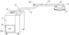
FIG. 1 is a schematic view of the construction of the scrap collecting apparatus of the present invention;
FIG. 2 is a top cross-sectional view of the debris suction cup of the present invention;
FIG. 3 is a front cross-sectional view of the scrap collecting box of the present invention;
FIG. 4 is a front cross-sectional view of a clearing bracket of the utility model.
In the figure: 1. a scrap collecting box; 2. a suction hose; 3. cleaning the bracket; 4. a chip suction cup; 5. removing hair by a scrap brush; 6. a drive motor; 7. a storage slot; 8. a switch plate; 9. a scrap collecting box; 10. a universal wheel; 11. a drive gear; 12. an annular inner rack; 13. an annular brush pad; 14. brushing off the ring groove; 15. a suction channel; 16. a horn-shaped scrap stop block; 17. a suction fan; 18. a filter screen frame; 19. a handle.
Detailed Description
The technical solution in the embodiments of the present invention will be clearly and completely described below with reference to the accompanying drawings in the embodiments of the present invention.
Referring to fig. 1-4, the utility model provides a scrap cleaning and collecting device for machining machine tool accessories, which comprises a scrap collecting box 1, a suction hose 2 is fixedly communicated with the middle part of the top end of the scrap collecting box 1, a scrap suction cup 4 is fixedly installed at one end of the suction hose 2, a driving motor 6 is fixedly installed at one side of the top end of the scrap suction cup 4, a suction channel 15 is arranged at the middle part of the bottom end of the scrap suction cup 4, a brushing annular groove 14 is arranged at the periphery of the bottom end of the scrap suction cup 4, an annular inner rack 12 is rotatably connected to one side of the inner wall of the brushing annular groove 14, an annular brush pad 13 is fixedly installed at the bottom end of the annular inner rack 12, a plurality of uniformly distributed scrap brushing hairs 5 are fixedly arranged at the bottom of the inner wall of the annular brush pad 13, a driving gear 11 is rotatably connected to the middle part of the inner wall of the brushing annular groove 14, a switch plate 8 is fixedly installed at one side of the top end of the scrap collecting box 1, the fixed surface of the switch board 8 is provided with the starting switch, the gap of the machine tool and the chips in the slot hole are cleaned in a negative pressure adsorption mode, the operation is simple and convenient, the cleaning efficiency of the chips is improved, and the cleaning mode of edge brushing and edge suction can be carried out on the scraps in the gap and other places through the hairbrush in the cleaning process, so that the cleaning effect is good.
The fixed clearance support 3 that is provided with in middle part on 4 tops of piece sucking disc, the fixed handle 19 that is provided with on clearance support 3, 1 top of sweeps collecting box keep away from one side of flashboard 8 offer with piece sucking disc 4 assorted storage slot 7, four corners of 1 bottom of sweeps collecting box are all fixed and are provided with universal wheel 10, and this sweeps collection device removes convenient to use fast, easy and simple to handle.
The output of driving motor 6 and the top fixed connection of driving gear 11, one side of driving gear 11 is connected with the inboard meshing of rack 12 in the annular, the fixed loudspeaker form sweeps dog 16 that is provided with in middle part of 1 inner wall of sweeps collecting box, the fixed filter screen frame 18 that is provided with in top of 1 inner wall of sweeps collecting box, the inboard fixed mounting of sweeps collecting box 1 and the filter screen frame 18 junction has suction fan 17, the positive block of sweeps collecting box 1 is connected with sweeps box 9 that concentrates, suction fan 17 and driving motor 6 are all through starting switch and external power supply electric connection, can not cause the damage to the lathe among the cleaning process, safety and reliability, the sweeps of clearance can concentrate and get into in the sweeps box 9 that concentrates and unify the collection, the clearance is convenient, therefore, the clothes hanger is strong in practicability.
When the embodiment of the application is used: the scrap collecting box 1 is directly pushed to a power supply beside a machine tool, then a worker takes out the cleaning support 3 from the containing clamping groove 7, the support is held to enable the scrap sucking disc 4 to be just opposite to the surface of the machine tool, the suction work of the scrap can be carried out by pressing a starting switch, the suction fan 17 enables the suction hose 2 and the scrap sucking disc 4 to generate suction force, the scrap collecting device is convenient and quick to move and use, the scraps in the gap and the groove hole of the machine tool are cleaned in a negative pressure adsorption mode, the operation is simple and convenient, the scrap cleaning efficiency is improved, the driving motor 6 can drive the driving gear 11 to rotate, the annular inner rack 12 drives the annular brush pad 13 and the scrap brush hair removal 5 to move, the scraps in the gap and the like can be cleaned in a mode of brushing and sucking simultaneously in the cleaning process, the cleaning effect is good, and the defect of poor cleaning effect of the traditional cleaning device is effectively avoided, can not cause the damage to the lathe, safe and reliable, the sweeps among the cleaning process can concentrate and get into the centralized box of sweeps 9 in and unify the collection, and the clearance is convenient, and the practicality is strong.
Although the present invention has been described in detail with reference to the foregoing embodiments, it will be apparent to those skilled in the art that various changes in the embodiments and/or modifications of the utility model can be made, and equivalents and modifications of some features of the utility model can be made without departing from the spirit and scope of the utility model.
Claims (6)
1. The utility model provides a sweeps clearance collection device is used in machine tool accessory processing, includes sweeps collecting box (1), its characterized in that: the middle part of sweeps collecting box (1) top is fixed and communicated with a suction hose (2), one end fixed mounting of suction hose (2) has a piece sucking disc (4), one side fixed mounting of piece sucking disc (4) top has a drive motor (6), the middle part of piece sucking disc (4) bottom has been seted up and has been sucked passageway (15), the periphery of piece sucking disc (4) bottom has been seted up and has been brushed off annular (14), one side of brushing off annular (14) inner wall is rotated and is connected with annular inner rack (12), the bottom mounting of annular inner rack (12) is provided with annular brush pad (13), the bottom mounting of annular brush pad (13) inner wall is provided with a plurality of evenly distributed pieces brush and removes hair (5), the middle part of brushing off annular (14) inner wall is rotated and is connected with drive gear (11), one side fixed mounting of sweeps collecting box (1) top has a switch board (8), and a starting switch is fixedly arranged on the surface of the switch plate (8).
2. The machine tool accessory processing scrap cleaning and collecting device according to claim 1, wherein: the middle part of the top end of the chip sucking disc (4) is fixedly provided with a cleaning support (3), and a handle (19) is fixedly arranged on the cleaning support (3).
3. The machine tool accessory processing scrap cleaning and collecting device according to claim 1, wherein: the output end of the driving motor (6) is fixedly connected with the top end of the driving gear (11), and one side of the driving gear (11) is meshed and connected with the inner side of the annular inner rack (12).
4. The machine tool accessory processing scrap cleaning and collecting device according to claim 1, wherein: the utility model discloses a dirty bits collection box, including sweeps collection box (1), filter screen frame (18), sweeps collection box (1) and driving motor (6), the fixed loudspeaker form sweeps dog (16) that is provided with in middle part of sweeps collection box (1) inner wall, the fixed filter screen frame (18) that is provided with in top of sweeps collection box (1) inner wall, the inboard fixed mounting of sweeps collection box (1) and filter screen frame (18) junction has suction fan (17), the positive block of sweeps collection box (1) is connected with sweeps box (9) of concentrating, suction fan (17) and driving motor (6) are all through starting switch and external power supply electric connection.
5. The machine tool accessory processing scrap cleaning and collecting device according to claim 1, wherein: and one side of the top end of the scrap collecting box (1) far away from the switch board (8) is provided with a containing clamping groove (7) matched with the scrap sucking disc (4).
6. The machine tool accessory processing scrap cleaning and collecting device according to claim 1, wherein: four corners at the bottom end of the scrap collecting box (1) are fixedly provided with universal wheels (10).
Priority Applications (1)
| Application Number | Priority Date | Filing Date | Title |
|---|---|---|---|
| CN202123264923.2U CN216706863U (en) | 2021-12-23 | 2021-12-23 | Sweeps clearance collection device is used in machine tool accessory processing |
Applications Claiming Priority (1)
| Application Number | Priority Date | Filing Date | Title |
|---|---|---|---|
| CN202123264923.2U CN216706863U (en) | 2021-12-23 | 2021-12-23 | Sweeps clearance collection device is used in machine tool accessory processing |
Publications (1)
| Publication Number | Publication Date |
|---|---|
| CN216706863U true CN216706863U (en) | 2022-06-10 |
Family
ID=81884753
Family Applications (1)
| Application Number | Title | Priority Date | Filing Date |
|---|---|---|---|
| CN202123264923.2U Active CN216706863U (en) | 2021-12-23 | 2021-12-23 | Sweeps clearance collection device is used in machine tool accessory processing |
Country Status (1)
| Country | Link |
|---|---|
| CN (1) | CN216706863U (en) |
-
2021
- 2021-12-23 CN CN202123264923.2U patent/CN216706863U/en active Active
Similar Documents
| Publication | Publication Date | Title |
|---|---|---|
| CN216706863U (en) | Sweeps clearance collection device is used in machine tool accessory processing | |
| CN215036086U (en) | Inner wall hole deburring mechanism | |
| CN212977865U (en) | Grinding machine special for parts | |
| CN215432744U (en) | Machine tool chip removal cleaning device for numerical control machine tool | |
| CN215967725U (en) | Spare part processingequipment of circular knitting machine | |
| CN210588376U (en) | Automatic cleaning device of workstation for machine tool machining | |
| CN211386941U (en) | Novel turret numerical control lathe | |
| CN212824037U (en) | Positioning and slotting device for fork shaft | |
| CN212265382U (en) | Inner hole grinding machine for gear production | |
| CN217551949U (en) | Numerical control screw tap thread machining grinding machine | |
| CN217799393U (en) | Flat-head lathe with workpiece positioning function | |
| CN220330718U (en) | High-precision milling machine | |
| CN219444566U (en) | Panel grinding device | |
| CN212822698U (en) | Turning and raised head removing device for large hexagon head bolt | |
| CN216462049U (en) | Milling machine chip cleaning device in milling machine workshop | |
| CN212192319U (en) | Full-automatic milling machine is used in optical instrument production convenient to clearance | |
| CN216327275U (en) | Environment-friendly grinding machine with self-cleaning function | |
| CN209850596U (en) | Fine sand polishing equipment for stainless steel products | |
| CN218194010U (en) | Vertical turning and grinding combined machine tool for electric spindle | |
| CN217573292U (en) | Lathe for wood working that possesses dust absorption function | |
| CN213946013U (en) | Polishing device for machining transmission part with good dust removal effect | |
| CN218802873U (en) | Environment-friendly plank cutting machine | |
| CN218194595U (en) | Polishing and grinding device for hardware fitting machining | |
| CN216802793U (en) | Automatic burring workstation of robot | |
| CN211193210U (en) | Deburring device for processing electrical switch |
Legal Events
| Date | Code | Title | Description |
|---|---|---|---|
| GR01 | Patent grant | ||
| GR01 | Patent grant |