CN216704401U - Drying device for activated carbon regeneration - Google Patents
Drying device for activated carbon regeneration Download PDFInfo
- Publication number
- CN216704401U CN216704401U CN202123204354.2U CN202123204354U CN216704401U CN 216704401 U CN216704401 U CN 216704401U CN 202123204354 U CN202123204354 U CN 202123204354U CN 216704401 U CN216704401 U CN 216704401U
- Authority
- CN
- China
- Prior art keywords
- drying
- activated carbon
- drying tank
- air
- tank
- Prior art date
- Legal status (The legal status is an assumption and is not a legal conclusion. Google has not performed a legal analysis and makes no representation as to the accuracy of the status listed.)
- Active
Links
Images

Landscapes
- Drying Of Solid Materials (AREA)
Abstract
The utility model discloses a drying device for activated carbon regeneration, which comprises a drying tank with a hollow interior, wherein material openings communicated with the inner cavity of the drying tank are formed in the upper part and the lower part of the side surface of the drying tank, a sealing plate for sealing the material openings is arranged on the side surface of the drying tank in a sliding manner, an air blowing assembly is arranged on the side surface of the drying tank, an air outlet of the air blowing assembly is communicated with the lower part of the inner cavity of the drying tank, a heating element for heating air is arranged on the side surface of the air blowing assembly, and an exhaust pipe communicated with the inner cavity of the drying tank is arranged on the upper part of the side surface of the drying tank. This drying device for active carbon regeneration, active carbon storage are in the drying cylinder to carry steam to the drying cylinder in by the outside subassembly of blowing and carry the active carbon to dry, the steam of carrying simultaneously plays the stirring effect to the active carbon, accelerates the efficiency of active carbon drying process, and steam is heated in being carried again to the heating member by the subassembly of blowing after to the active carbon drying, makes steam circulation flow, reduces the power consumption of heating member.
Description
Technical Field
The utility model relates to the technical field of drying devices, in particular to a drying device for activated carbon regeneration.
Background
The active carbon is suitable for fields such as drying, filtration, deodorization because of having good adsorption effect, and its adsorption efficiency descends or even does not have adsorption effect after the active carbon uses, and the active carbon after the use is called useless active carbon, and useless active carbon handles improper meeting and causes the wasting of resources or even polluted environment, need dry useless active carbon when useless active carbon handles, but common drying device's drying effect is relatively poor, the energy loss is more, leads to active carbon regeneration efficiency low, the energy consumption is high.
SUMMERY OF THE UTILITY MODEL
The technical problem to be solved by the utility model is to overcome the existing defects and provide a drying device for regenerating activated carbon, wherein the activated carbon is stored in a drying tank, hot air is conveyed into the drying tank from an external air blowing assembly to dry the activated carbon, the conveyed hot air has a stirring effect on the activated carbon, the drying treatment efficiency of the activated carbon is accelerated, the hot air is conveyed into a heating element again by the air blowing assembly after drying the activated carbon to heat the activated carbon, the hot air flows circularly, the energy consumption of the heating element is reduced, and the problems in the background art can be effectively solved.
In order to achieve the purpose, the utility model provides the following technical scheme: the utility model provides an active carbon is drying device for regeneration, includes inside hollow drying cabinet, the material mouth rather than the inner chamber intercommunication is all seted up to drying cabinet side upper portion and side lower part, the sliding of drying cabinet side is provided with the closing plate sealed to the material mouth.
The drying cylinder side is provided with the subassembly of blowing, the gas outlet and the drying cylinder inner chamber lower part intercommunication of the subassembly of blowing, the subassembly side of blowing is provided with the heating member to gas heating, the blast pipe rather than the inner chamber intercommunication is installed on drying cylinder side upper portion, the drying cylinder outside is provided with the switch group, the input of switch group is connected with the output electricity of external power source.
As a preferable technical scheme of the utility model, the air blowing assembly comprises an air pump fixed on the outer side of the drying tank, an air guide pipe communicated with the lower part of the inner cavity of the drying tank is arranged at an air outlet of the air pump, and the input end of the air pump is electrically connected with the output end of the switch group.
As a preferable technical scheme, the heating element comprises a heating box fixed on the side face of the drying tank, an electric heating net is installed in the heating box, one end, far away from the air pump, of the air guide pipe is communicated with the inner cavity of the heating box, an air blowing pipe communicated with the lower side of the inner cavity of the drying tank is installed in an air exhaust hole in the side face of the heating box, an air inlet valve is installed at the position, close to the drying tank, of the outer side of the air blowing pipe, and the input end of the electric heating net is electrically connected with the output end of the external switch group.
As a preferred technical scheme of the utility model, the end part of the exhaust pipe is provided with a filter box, a filter piece is arranged in the filter box, and the lower side of the filter box is provided with a communicating pipe communicated with the inner cavity of the gas guide pipe.
As a preferable technical scheme of the utility model, a motor is fixed on the upper side of the drying tank, a stirring dragon positioned in the drying tank is installed on an output shaft of the motor, and an input end of the motor is electrically connected with an output end of the switch group.
As a preferable technical scheme of the utility model, a U-shaped limiting frame is arranged at the position, close to the material port, of the side surface of the drying tank, and the sealing plate is arranged in the limiting frame in a sliding mode.
Compared with the prior art, the utility model has the beneficial effects that:
1. according to the drying device for activated carbon regeneration, the activated carbon is stored in the drying tank, the hot air is conveyed into the drying tank by the external air blowing assembly to dry the activated carbon, the conveyed hot air has a stirring effect on the activated carbon, the drying treatment efficiency of the activated carbon is accelerated, the hot air is conveyed into the heating element again by the air blowing assembly to be heated after drying the activated carbon, the hot air flows circularly, and the energy consumption of the heating element is reduced.
2. According to the drying device for activated carbon regeneration disclosed by the utility model, activated carbon to be dried is placed into the drying tank through the material opening at the upper part of the side surface of the drying tank, then the sealing plate is slid to seal the material opening, the air pump and the electric heating net are started, the air pump conveys the extracted air into the heating box through the air guide pipe, the electric heating net heats the air, the heated air enters the drying tank through the air blowing pipe to dry the activated carbon, and meanwhile, the activated carbon in the drying tank is stirred when the air is sprayed out through the air blowing pipe, so that the drying efficiency of the activated carbon is improved.
3. According to the drying device for activated carbon regeneration disclosed by the utility model, the gas entering the drying tank is discharged into the filter box through the exhaust pipe, the filtering piece is used for filtering and adsorbing activated carbon dust, moisture and the like carried in the gas, the filtered gas enters the gas guide pipe through the communicating pipe and is heated by the electric heating net again to dry the activated carbon in the drying tank, the heated gas is recycled, and the energy consumption of the electric heating net in the drying device is reduced.
4. According to the drying device for activated carbon regeneration, when the humidity of the activated carbon in the drying tank is too high or hardening exists, so that gas cannot stir the activated carbon, the motor is started to drive the stirring auger to rotate to stir and extrude the activated carbon, so that the gas is conveniently introduced into the drying tank to dry the activated carbon, after the activated carbon is dried, the sealing plate at the lower part of the side surface of the drying tank is slid to open the material opening, and the dried activated carbon is taken out of the drying tank.
Drawings
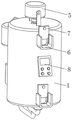
FIG. 1 is a schematic structural view of the present invention;
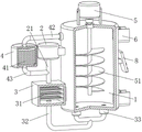
FIG. 2 is a schematic cross-sectional view of the present invention;
fig. 3 is a schematic view of another structure according to the present invention.
In the figure: the device comprises a drying tank 1, an air pump 2, an air duct 21, a heating box 3, an electric heating net 31, an air blowing pipe 32, an air inlet valve 33, a filtering box 4, a filtering piece 41, an exhaust pipe 42, a communicating pipe 43, a motor 5, a stirring dragon 51, a limiting frame 6, a sealing plate 7 and a switch group 8.
Detailed Description
The technical solutions in the embodiments of the present invention will be clearly and completely described below with reference to the drawings in the embodiments of the present invention, and it is obvious that the described embodiments are only a part of the embodiments of the present invention, and not all of the embodiments. All other embodiments, which can be derived by a person skilled in the art from the embodiments given herein without making any creative effort, shall fall within the protection scope of the present invention.
Referring to fig. 1-3, the present invention provides a technical solution: the utility model provides a drying device for active carbon regeneration, includes inside hollow drying can 1, and the preferred heat preservation material of drying can 1, the material mouth rather than the inner chamber intercommunication is all seted up to drying can 1 side upper portion and side lower part, and the material mouth of upside is used for the interpolation of active carbon, and the material mouth of downside is used for taking out of active carbon, and the sliding seal plate 7 that is provided with to the material mouth is sealed to drying can 1 side, and the sealed effect of drying can 1 is guaranteed to closing plate 7.
The side of the drying tank 1 is provided with a blowing component, the gas outlet of the blowing component is communicated with the lower part of the inner cavity of the drying tank 1, the side of the blowing component is provided with a heating element for heating gas, the upper part of the side of the drying tank 1 is provided with an exhaust pipe 42 communicated with the inner cavity of the drying tank, the blowing component extracts gas through the exhaust pipe 42 to enable the heated gas to be recycled, the outer side of the drying tank 1 is provided with a switch group 8, and the input end of the switch group 8 is electrically connected with the output end of an external power supply.
The blowing assembly comprises an air pump 2 fixed on the outer side of the drying tank 1, an air guide pipe 21 communicated with the lower part of the inner cavity of the drying tank 1 is arranged at the air outlet of the air pump 2, the input end of the air pump 2 is electrically connected with the output end of the switch group 8, and air pumped by the air pump 2 is conveyed into the drying tank 1 through the air guide pipe 21.
The heating member is including fixing the heating cabinet 3 in 1 side of drying cabinet, install electric heating net 31 in the heating cabinet 3, the one end and the 3 inner chambers of heating cabinet intercommunication of air pump 2 are kept away from to air duct 21, install the gas blow pipe 32 with 1 inner chamber downside intercommunication of drying cabinet in the exhaust port of 3 sides of heating cabinet, and the position department that the gas blow pipe 32 outside is close to drying cabinet 1 installs admission valve 33, admission valve 33 is the check valve, inside admission valve 33 avoided the active carbon to get into gas blow pipe 32, electric heating net 31's input is connected with external switch group's output electricity.
Will treat the dry active carbon through the material mouth on 1 side upper portion of drying cabinet and put into drying cabinet 1 in, later sliding seal board 7 is sealed to the material mouth, start air pump 2 and electric heating net 31, air pump 2 will take out the gas transport of getting to heating cabinet 3 in through air duct 21, electric heating net 31 is to gas heating, and the gas after the heating is dried to the active carbon in getting into drying cabinet 1 through gas blow pipe 32, the active carbon of drying cabinet 1 is stirred when gas passes through gas blow pipe 32 blowout simultaneously, active carbon drying efficiency is improved.
The gas-guide tube 21, the gas blowing pipe 32, the gas exhaust pipe 42 and the communication pipe 43 are preferably rigid pipes.
The tip of blast pipe 42 is provided with rose box 4, be provided with in the rose box 4 and filter 41, the communicating pipe 43 with air duct 21 inner chamber intercommunication is installed to rose box 4 downside, the gas that gets into in the drying cabinet 1 discharges to rose box 4 in through blast pipe 42, filter 41 filters the absorption to the active carbon dust and moisture etc. that carry in the gas, the gas after the filtration gets into in air duct 21 through communicating pipe 43 and passes through electric heating net 31 heating once more and carries out the drying to the active carbon in the drying cabinet 1, the gas cycle after the heating uses, reduce the power consumption of electric heating net 31 in this drying device.
1 upside of drying can is fixed with motor 5, install the stirring flood dragon 51 that is located drying can 1 on motor 5's the output shaft, motor 5's input is connected with switch 8's output electricity, activated carbon humidity in drying can 1 is too big or there is the hardening to lead to when gaseous can't stir it, starter motor 5 drives stirring flood dragon 51 and rotates and stir and extrude the activated carbon, be convenient for gaseous letting in drying can 1 in carry out drying process to the activated carbon, the feed opening is opened to closing plate 7 of the dry 1 side lower part of back slip drying can of accomplishing of activated carbon, take out the activated carbon after the drying from drying can 1.
The U-shaped limiting frame 6 is installed at a position, close to the material opening, on the side face of the drying tank 1, the sealing plate 7 is arranged in the limiting frame 6 in a sliding mode, the limiting frame 6 is used for storing and restraining the activated carbon, and the activated carbon is prevented from being scattered when being added or taken out.
The air pump 2, the electric heating net 31, the motor 5, the switch group 8 and the like used in the present invention are all common electronic components in the prior art, and the working mode and the circuit structure thereof are all known technologies, and are not described herein again.
When in use:
the method comprises the steps that activated carbon to be dried is placed into a drying tank 1 through a material opening in the upper portion of the side face of the drying tank 1, then a sliding sealing plate 7 is sealed to the material opening, an air pump 2 and an electric heating net 31 are started, the air pump 2 conveys pumped air into a heating box 3 through an air guide pipe 21, the electric heating net 31 heats the air, the heated air enters the drying tank 1 through an air blowing pipe 32 to dry the activated carbon, and meanwhile, the activated carbon in the drying tank 1 is stirred when the air is sprayed out through the air blowing pipe 32, so that the drying efficiency of the activated carbon is improved;
the gas entering the drying tank 1 is discharged into the filter box 4 through the exhaust pipe 42, the filtering piece 41 filters and adsorbs the activated carbon dust, moisture and the like carried in the gas, the filtered gas enters the gas guide pipe 21 through the communicating pipe 43 and is heated by the electric heating net 31 again to dry the activated carbon in the drying tank 1, the heated gas is recycled, and the energy consumption of the electric heating net 31 in the drying device is reduced;
when activated carbon humidity in drying can 1 is too big or there is to harden and lead to gaseous unable stirring to it, starter motor 5 drives stirring flood dragon 51 and rotates and stir and extrude the activated carbon, and the gaseous drying process is carried out to the activated carbon in letting in drying can 1 of being convenient for, and the feed opening is opened to the closing plate 7 of the dry 1 side lower part of slip drying can after the activated carbon drying is accomplished, takes out the activated carbon after will drying from drying can 1.
This drying device for active carbon regeneration, active carbon storage are in the drying cylinder to carry steam to the drying cylinder in by the outside subassembly of blowing and carry the active carbon to dry, the steam of carrying simultaneously plays the stirring effect to the active carbon, accelerates the efficiency of active carbon drying process, and steam is heated in being carried again to the heating member by the subassembly of blowing after to the active carbon drying, makes steam circulation flow, reduces the power consumption of heating member.
The parts which are not disclosed in the utility model are all the prior art, and the specific structure, the materials and the working principle are not detailed. Although embodiments of the present invention have been shown and described, it will be appreciated by those skilled in the art that changes, modifications, substitutions and alterations can be made in these embodiments without departing from the principles and spirit of the utility model, the scope of which is defined in the appended claims and their equivalents.
Claims (6)
1. The utility model provides an active carbon is drying device for regeneration, includes inside hollow drying cylinder (1), its characterized in that: the upper part and the lower part of the side surface of the drying tank (1) are both provided with a material port communicated with the inner cavity of the drying tank, and the side surface of the drying tank (1) is slidably provided with a sealing plate (7) for sealing the material port;
the utility model discloses a dryer, including retort (1), blow subassembly, blast pipe (42) that the gas outlet of subassembly and retort (1) inner chamber lower part intercommunication blow, the subassembly side of blowing is provided with the heating member to gas heating, retort (1) side upper portion is installed rather than the inner chamber intercommunication, retort (1) outside is provided with switch group (8), the input of switch group (8) is connected with external power source's output electricity.
2. The drying device for activated carbon regeneration according to claim 1, characterized in that: the air blowing assembly comprises an air pump (2) fixed on the outer side of the drying tank (1), an air guide pipe (21) communicated with the lower portion of an inner cavity of the drying tank (1) is arranged at an air outlet of the air pump (2), and the input end of the air pump (2) is electrically connected with the output end of the switch group (8).
3. The drying device for activated carbon regeneration according to claim 2, characterized in that: the heating member is including fixing heating cabinet (3) in drying cylinder (1) side, install electric heating net (31) in heating cabinet (3), the one end and the heating cabinet (3) inner chamber intercommunication of air pump (2) are kept away from in air duct (21), install in the exhaust hole of heating cabinet (3) side with blowing pipe (32) of drying cylinder (1) inner chamber downside intercommunication, and blowing pipe (32) outside is close to position department of drying cylinder (1) and installs admission valve (33), the input of electric heating net (31) is connected with external switch group's output electricity.
4. The drying device for activated carbon regeneration according to claim 2, characterized in that: the tip of blast pipe (42) is provided with rose box (4), be provided with in rose box (4) and filter piece (41), communicating pipe (43) with air duct (21) inner chamber intercommunication are installed to rose box (4) downside.
5. The drying device for activated carbon regeneration according to claim 1, characterized in that: the drying cylinder (1) upside is fixed with motor (5), install flood stirring dragon (51) that are located drying cylinder (1) on the output shaft of motor (5), the input of motor (5) is connected with the output electricity of switch block (8).
6. The drying device for activated carbon regeneration according to claim 1, characterized in that: the drying tank is characterized in that a U-shaped limiting frame (6) is installed at a position, close to the material port, of the side face of the drying tank (1), and the sealing plate (7) is arranged in the limiting frame (6) in a sliding mode.
Priority Applications (1)
| Application Number | Priority Date | Filing Date | Title |
|---|---|---|---|
| CN202123204354.2U CN216704401U (en) | 2021-12-20 | 2021-12-20 | Drying device for activated carbon regeneration |
Applications Claiming Priority (1)
| Application Number | Priority Date | Filing Date | Title |
|---|---|---|---|
| CN202123204354.2U CN216704401U (en) | 2021-12-20 | 2021-12-20 | Drying device for activated carbon regeneration |
Publications (1)
| Publication Number | Publication Date |
|---|---|
| CN216704401U true CN216704401U (en) | 2022-06-10 |
Family
ID=81884333
Family Applications (1)
| Application Number | Title | Priority Date | Filing Date |
|---|---|---|---|
| CN202123204354.2U Active CN216704401U (en) | 2021-12-20 | 2021-12-20 | Drying device for activated carbon regeneration |
Country Status (1)
| Country | Link |
|---|---|
| CN (1) | CN216704401U (en) |
-
2021
- 2021-12-20 CN CN202123204354.2U patent/CN216704401U/en active Active
Similar Documents
| Publication | Publication Date | Title |
|---|---|---|
| CN204997794U (en) | Eliminate wooden board free formaldehyde device | |
| CN112827279A (en) | Environment-friendly industrial waste gas treatment device | |
| CN210892450U (en) | Novel drying box | |
| CN216704401U (en) | Drying device for activated carbon regeneration | |
| CN109985501A (en) | A kind of printing and dyeing exhaust gas three-stage processing equipment | |
| CN213853900U (en) | Integrated form VOC exhaust treatment device | |
| CN212492245U (en) | Improved generation organic waste gas adsorption tower | |
| CN215864540U (en) | Modified plastics production removes circulation of smell and removes VOC and dries by fire material jar | |
| CN213631249U (en) | A heated air circulation oven for traditional chinese medicine material is dry | |
| CN207865545U (en) | A kind of efficient formaldehyde purifier for the treatment of indoor air pollution | |
| CN210773566U (en) | Waste heat recovery device for environmental engineering waste gas treatment | |
| CN207962996U (en) | A kind of rotary dehumidifier | |
| CN208557992U (en) | A kind of airflow heating device | |
| CN212457801U (en) | Be applied to high-efficient drying device of medical treatment | |
| CN206944393U (en) | A kind of deodorizing device for confined space | |
| CN218973109U (en) | High temperature heat pump dryer | |
| CN218238217U (en) | Preheating-type sodium sulfite drying device | |
| CN220201446U (en) | Helium purification is with high-efficient purification device | |
| CN213623347U (en) | Sewage station odor treatment device | |
| CN215864455U (en) | Composite flame retardant drying equipment | |
| CN220741851U (en) | Epoxy powder premix shaping solidification equipment | |
| CN216011305U (en) | Water heater waste gas recovery processing mechanism suitable for dish washer | |
| CN220524142U (en) | Boiler waste heat utilization device | |
| CN220424964U (en) | Air drying device system | |
| CN209840412U (en) | Blast air gas pretreatment device |
Legal Events
| Date | Code | Title | Description |
|---|---|---|---|
| GR01 | Patent grant | ||
| GR01 | Patent grant |