CN216663711U - Micro-surfacing paver - Google Patents
Micro-surfacing paver Download PDFInfo
- Publication number
- CN216663711U CN216663711U CN202121887434.XU CN202121887434U CN216663711U CN 216663711 U CN216663711 U CN 216663711U CN 202121887434 U CN202121887434 U CN 202121887434U CN 216663711 U CN216663711 U CN 216663711U
- Authority
- CN
- China
- Prior art keywords
- mineral aggregate
- shovel
- conveying
- asphalt
- micro
- Prior art date
- Legal status (The legal status is an assumption and is not a legal conclusion. Google has not performed a legal analysis and makes no representation as to the accuracy of the status listed.)
- Active
Links
Images


Classifications
-
- Y—GENERAL TAGGING OF NEW TECHNOLOGICAL DEVELOPMENTS; GENERAL TAGGING OF CROSS-SECTIONAL TECHNOLOGIES SPANNING OVER SEVERAL SECTIONS OF THE IPC; TECHNICAL SUBJECTS COVERED BY FORMER USPC CROSS-REFERENCE ART COLLECTIONS [XRACs] AND DIGESTS
- Y02—TECHNOLOGIES OR APPLICATIONS FOR MITIGATION OR ADAPTATION AGAINST CLIMATE CHANGE
- Y02A—TECHNOLOGIES FOR ADAPTATION TO CLIMATE CHANGE
- Y02A30/00—Adapting or protecting infrastructure or their operation
- Y02A30/60—Planning or developing urban green infrastructure
Abstract
The utility model discloses a micro-surfacing paver integrating receiving, transferring and batching, micro-wound pretreatment, spraying, stirring and paving, which comprises a rack, an internal combustion engine, a transfer case, a receiving hopper, a mineral aggregate transferring system, a waterway transferring system, an asphalt transferring system, a walking device, an operation platform, a pavement pretreatment device, a spraying device, a stirring device and a paving device, wherein the internal combustion engine is connected with the transfer case through a pipeline; after receiving and buffering all raw materials, metering and proportioning the raw materials, mixing the raw materials into a mixture, flowing the mixture into a spreading device for spreading, and preprocessing minimally invasive punching and milling and brushing of the road surface and asphalt spraying in real time. The operation and control are simple, the material receiving is easy and convenient, the yield is large, the efficiency is high, and the performance is reliable; the problems of longitudinal and transverse seams and stub bars are effectively solved, and the phenomenon of different paving quality is avoided; the proportioning precision is high, the paving width is wide, and the interlayer adhesive force is strong; the quality performance is superior, and the service life of the pavement is prolonged. Can be used for cold mixing and cold spreading and in-situ cold regeneration spreading. Is suitable for construction in various operation surfaces and environments.
Description
Technical Field
The utility model belongs to the field of engineering machinery required by road and airport construction, maintenance and repair and other pavement operations. In particular to a slurry seal vehicle and micro-surfacing paving equipment.
Background
Micro surfacing and slurry sealing technologies have become an important component in road construction and pavement maintenance and repair projects. The micro-surfacing and slurry sealing is that a slurry mixture is formed by continuously mixing stone grains or sand, stone powder, cement, water and additives with certain gradation with emulsified asphalt (high molecular polymer modified emulsified asphalt), then the mixture is quickly and uniformly spread on the road surface to be constructed, and then the processes of emulsion breaking, water separation, evaporation, solidification, forming and the like are carried out to form a sealing or rutting filler. The method can be used for performing preventive maintenance, early maintenance, rut filling and repairing, pavement appearance improvement and the like on the surface function of the road. The adhesive has the functions of adhesion, water resistance and the like in the lower sealing layer in the construction of the road surface and the airport runway. Effectively improves the road service performance and prolongs the service life of the road. Micro-surfacing, slurry seal paving equipment and a construction technical method have important influence on construction quality and performance.
At present, the micro surfacing and slurry seal construction in China generally adopts a slurry seal vehicle to carry out paving operation in an intermittent process. The method comprises the steps of filling raw materials such as mineral aggregate, emulsified asphalt, water and the like in a stock yard, driving the stock yard to a construction site for construction operation, obtaining the stock yard again when a certain raw material is used up, and repeating the construction. The limited quantity of raw materials is limited when the slurry seal vehicle is filled with one vehicle, and only a limited area can be paved due to the requirements of different widths and thicknesses; in the long-distance large engineering construction, the equipment must return to a stock yard to be additionally provided with raw materials and then drives to the construction site again to carry out the next construction operation. Therefore, most time of equipment is wasted on transporting raw materials, high equipment utilization rate is low, and construction efficiency is not ideal. Usually, a plurality of devices are adopted to sequentially operate in turn in large-scale engineering, so that the paving joint is easy to frequently occur in the long-distance construction process to influence the quality of the whole pavement. The low-speed and constant-speed running of the truck chassis under the working conditions of heavy load and load change in the construction process is difficult to control; the low-speed and uniform-speed running range of the truck chassis is very limited, and the control and the adjustment are more difficult to realize under the working condition of heavy load and load change. The reduction ratio of the truck chassis gearbox is also troubled by the fact that the low-speed construction speed and the high-speed transportation running speed cannot be achieved at the same time. Different operation personnel of different model equipment often can take place different shop front quality phenomena at same construction road section construction operation, especially different appearance quality problem. In addition, each operation necessarily generates a process stub bar, and the process stub bar is generally discarded. The generated stub bar waste is accumulated on the total engineering quantity in a non-small amount, so that a large amount of non-renewable resources are wasted, the capital loss is caused, and the natural environment is damaged.
Although the existing continuous micro-surfacing equipment can avoid the problems of frequent generation of stub bars, joints and the like in an intermittent process theoretically, the theoretical construction quality and the construction efficiency are superior to those of intermittent process construction. However, most of the existing continuous slurry seal vehicles and continuous micro-surfacing equipment currently need special supporting equipment, and one type is as follows: the special material transfer vehicle is provided with emulsified asphalt, water and mineral aggregate supply on the same vehicle; the other is that: and feeding materials right in front of the slurry vehicle by adopting independent continuous feeding equipment, and sequentially conveying the emulsified asphalt, the water and the mineral aggregate in batches by the material conveying vehicle, the feeding equipment and the slurry seal vehicle in sequence. But the foreign continuous equipment introduced in the real production has not been accepted and recognized by the domestic market and the industry for a long time! Slurry seal vehicle-type micro-surfacing equipment construction is widely used in China for a long time. Although the related technologies of continuous micro-surfacing or slurry seal equipment and construction methods are disclosed and introduced in quite a lot of literature documents, the operability, popularization, reliability, construction quality, cost and the like of the related technologies are far from the comprehensive application performance of slurry seal vehicles, and the real objects are rarely seen in actual production. The reason for this phenomenon is mainly three-fold: firstly, the existing continuous slurry seal or micro-surfacing equipment has strict requirements on the level of construction operation and management personnel, the loading process is complicated, the equipment is not easy to operate, and the construction quality is difficult to control; secondly, special matching equipment matched with the special matching equipment needs to be adopted, and particularly, the overall use cost of the matching equipment is high; and then the continuous, smooth and stable matching operation among matched equipment is complicated and very difficult. The above-mentioned historical problems have long existed.
Because the existing equipment design shows: the effective power of the equipment is limited, and the capacity for stirring the emulsified asphalt mixture is limited, so that the existing continuous and discontinuous micro-surfacing process can only meet the requirement of paving the asphalt mixture in the width of one lane at one time. Therefore, the lanes with more than two widths are spliced and paved in sequence, segregation occurs at the longitudinal joint, the flatness of the longitudinal joint is easy to generate high-low dislocation, the lap joint bonding degree and the strength of the longitudinal joint are weak, and the quality problems of the flatness of the whole pavement, the appearance color difference and the like are very difficult to control.
A great deal of research at home and abroad shows that the improper treatment between pavement layers is one of the important reasons for causing the quality problem of micro-surfacing or slurry sealing pavement, because the original road surface layer and the slurry sealing or micro-surfacing surface layer are two materials and processes with different structures, if the interlayer binding force is insufficient, the load caused by road running is added alternately in four seasons in the natural environment, particularly heavy load and overload, and the extrusion and shear deformation between the layers are continuously accumulated, so that the problems of premature falling, cracks, rough surfaces, pushing, uneven pavement and the like of the slurry sealing or micro-surfacing pavement are caused.
In addition, the existing equipment design scheme shows that: the effective power of the equipment is limited, and the functionality is single, so that the prior micro-surfacing pretreatment process for the pavement needs to be carried out in advance by using separate equipment. Thereby the unrestrained mineral aggregate can't in time be cleared up in the work progress, must cause the device of paving to be raised in a same place and slide produced quality problems such as lou material, race material, directly influence the quality effect that paves. In particular to a method for pretreating the road surface before paving construction at present, which generally adopts non-special cleaning equipment and a shoulder portable blower to pretreat the road surface before construction. The method obviously has very limited road surface cleaning effect on the deposited ash layer, the asphalt oxidation layer, the unstable material and the like of the original road surface, and can not meet the design requirement of the construction process. And the method is very labor-consuming, time-consuming, low in construction efficiency, large in occupied equipment and manpower, high in construction cost and uneconomical.
The above problems have not been solved effectively.
Disclosure of Invention
The utility model aims to solve the technical defects and provides the intelligent micro-surfacing paver. The method has two functions of continuous construction and intermittent construction; the asphalt mixture stirring device has the functions of high-precision proportioning feeding and high-efficiency and uniform stirring of asphalt mixtures with large yield so as to pave a pavement; the paving width can be paved on a single lane or on multiple lanes at one time, and the change is simple, flexible and various; a 'dry' and 'wet' minimally invasive pretreatment device is specially and innovatively designed to implement minimally invasive punching and milling and minimally invasive milling and sweeping so as to remarkably enhance the interlayer adhesive force of pavement; the multifunctional intelligent material conveying device has the advantages of multifunction, multiple purposes and intelligence, and simple and easy operation, and particularly, the material conveying between devices is simple, convenient and quick. Namely, the present invention can simultaneously: the process procedures of receiving materials, measuring and transferring raw materials, carrying out minimally invasive pretreatment (high-pressure water minimally invasive punching and milling, minimally invasive milling and brushing), spraying asphalt, stirring, spreading, leveling and the like are integrated into a whole to complete the paving or rutting filling operation at one time. Particularly, the design scheme is innovative and novel, other special supporting equipment is not needed, namely, the construction process can be synchronously, simply, conveniently, easily and quickly and continuously transferred and supplied with raw materials only by a general dump truck and a water and emulsified asphalt transport vehicle, so that the long-distance multi-lane large-width continuous paving construction operation without stopping smoothly and stably is realized. The method is easy and simple to operate, effectively solves the problems of longitudinal joints, transverse joints and stub bars, eliminates the appearance color difference of pavement and the phenomenon of different paving quality, perfectly enhances the interlayer adhesive force by the minimally invasive pretreatment design, and reduces the premature occurrence of pavement diseases. The utility model has the advantages that the precision of each raw material for transmission and proportioning is accurate and sensitive, the stirring is uniform and efficient, and the yield is high; the paving width can be adjusted in a wide and flexible range, the maximum paving width can reach 11 m at one time, and the paving width has larger width expansion potential; the travelling speed is stable and adjustable during construction operation, and the paving speed is constant and powerful; the device can be controlled and regulated in a stepless and flexible way from low speed to high speed, and is smooth and stable; the construction quality performance is excellent, the low carbon and environmental protection are realized, and the service life of the pavement is prolonged. The construction method is suitable for construction under various working surfaces and environments, scientific and reasonable in equipment structure layout, reliable in performance, low in use and maintenance cost and high in cost performance. The utility model also has the advantages that the cold-mixing cold-paving and in-situ cold-recycling or in-situ cold-mixing cold-recycling paving construction operation can be carried out without changing the structure and the system of the equipment. Is suitable for construction in various working surfaces and environments.
In order to achieve the purpose, the utility model provides the following technical scheme: a micro-surfacing paver is characterized by comprising a rack (namely a chassis), an internal combustion engine, a transfer case, a hydraulic system, an air circuit system, a circuit system, an operation platform, a control system, a push roller, a push shovel device, a walking device, a receiving hopper, a mineral aggregate transferring system, a water path transferring system, an asphalt transferring system, an additive adding system, an asphalt spraying device, a stirring device and a paving device. The left side and the right side of the bottom of the frame are symmetrically provided with a traveling device in parallel. The internal combustion engine and the transfer case are fixed in the rear part of the frame above the walking device, the power input port of the transfer case is in transmission connection with the power output port of the crankshaft of the internal combustion engine, the power is distributed by the transfer case, each power output port of the transfer case is in transmission connection with a hydraulic pump matched with each function so as to drive components such as a hydraulic motor, a hydraulic oil cylinder and the like of each function, and the power take-off port of the internal combustion engine is in transmission connection with a corresponding hydraulic pump so as to drive components such as a corresponding hydraulic motor or a hydraulic oil cylinder and the like. The front end of the frame is provided with a pushing roller for pushing the tires of the mineral aggregate conveying vehicle to move ahead synchronously. The shovel pushing device is preferably arranged below the front portion of the frame and on the front side of the walking device. The receiving hopper is arranged above the front part of the frame. Mineral aggregate transferring systems are arranged at the space positions of the lower side of the bottom of the receiving hopper, the rear side of the receiving hopper, the front side of the internal combustion engine and the upper side of the internal combustion engine, the mineral aggregate transferring systems mainly comprise four parts, namely a I-level parallel conveying functional mechanism, a II-level lifting functional mechanism, a III-level mineral aggregate caching functional mechanism and a IV-level parallel conveying functional mechanism, and a feeding hole of the mineral aggregate transferring systems is communicated with a discharging hole in the bottom of the lower side of the receiving hopper. And the pitch transferring system and the water path transferring system are arranged at the front side and the upper side of the internal combustion engine and at the space positions of the two sides of the mineral aggregate transferring system. And the middle part of the rear side of the frame is provided with a stirring device, and a discharge hole of the mineral aggregate transferring system is arranged right above a feed hole of the stirring device and communicated with the feed hole. The additive adding system is arranged at the rear side of the frame and above the stirring device, and a discharge port of the additive adding system is arranged above and communicated with a feed port of the stirring device. The control platform and the control system (control cabinet) are arranged on the rear side of the frame and on the upper side or the right side or the left side of the stirring device. The spreading device is arranged below the discharge port of the stirring device and is connected with the micro-surfacing spreader in a dragging mode, and the spreading device can be selected from different manufacturers and different models.
The shovel pushing device is preferably fixed by bolts or is arranged at the space positions below the front part of the frame, on the lower side of the push roller and on the front side of the walking device in a quick dismounting mode; or the rear space position of the walking device is arranged below the rear part of the frame; or the space position between the lower part of the middle part of the frame and the front walking device and the rear walking device. The method realizes that mineral aggregate and other useless objects scattered in the construction process are quickly pushed to two sides of the pavement to be constructed.
In the above scheme, the shovel pushing device comprises a shovel pushing support, a shovel plate and a lifting mechanism. The shovel plate is orderly arranged on the lower edge of the push shovel bracket. The pushing and lifting mechanism adopts an oil cylinder and a connecting rod mechanism, so that the pushing shovel bracket can float up and down, and the lower edge of the shovel plate is driven to be in linear contact with and separate from the road surface.
In the above scheme, the shovel pushing device comprises a shovel pushing lengthened support and a shovel pushing support rod. The push shovel lengthened support and the push shovel support are fixedly connected through a quick detachable bolt; one end of the push shovel supporting rod is hinged with the push shovel lengthening support, and the other end of the push shovel supporting rod is hinged with the walking device beam or the push shovel supporting rod on the rack to be seated and used for supporting the lengthening part of the shovel device. The shovel plate is arranged on the lower edge of the push shovel lengthening support.
In the above scheme, the effective working width of the push shovel device in the construction operation, namely the required lengthening distance, is matched with the paving width, and the push shovel device is flexibly spliced. Shovel plates fixed by a bracket of the shovel pushing device are bilaterally symmetrical to form an included angle on the central axis of the rack, and the arrow-shaped shovel plates are beneficial to pushing and discharging materials to two sides in the construction process; or the shovel plate shape straight line fixed by the shovel device bracket forms a small included angle with the central axis of the frame as much as possible, namely the straight line is inclined to one side, which is beneficial to pushing and discharging materials to one side in the construction process; or the shovel plate fixed by the bracket of the push shovel device is shaped into a straight line which is vertical to the central axis of the frame, and the shovel plate is similar to a push shovel of a bulldozer to push the scattered mineral aggregate and other useless objects forward to be collected and cleaned regularly.
The mineral aggregate transferring system comprises a mineral aggregate conveying and lifting device, a mineral aggregate caching bin and a mineral aggregate conveying device IV. The mineral aggregate conveying and lifting device has I-level parallel conveying and II-level lifting of mineral aggregates, mineral aggregate caching bins finish III-level mineral aggregate caching, the mineral aggregate conveying device IV achieves IV-level parallel conveying functions, and the mineral aggregates in the receiving hopper are conveyed to the stirring device together. The mineral aggregate lifting and conveying device integrally completes the functions of parallel conveying and level lifting conveying, and is arranged on the lower side and the rear side of the receiving hopper and the front side and the upper space position of the engine. A feed port of the mineral aggregate conveying and lifting device (namely a feed port of the mineral aggregate transferring system) is communicated with a discharge port of the receiving hopper; the mineral aggregate buffer bin is arranged below a discharge port of the mineral aggregate conveying and lifting device; the mineral aggregate conveying device IV is arranged in a space position between the lower side of the mineral aggregate buffer bin and the upper side of the engine, a discharge hole of the mineral aggregate buffer bin is communicated with a feed hole of the mineral aggregate conveying device IV, and a discharge hole of the mineral aggregate conveying device IV (namely a discharge hole of the mineral aggregate conveying system) is arranged above the feed hole of the stirring device and is communicated with the feed hole.
The mineral aggregate conveying and lifting device integrally and simultaneously completes the functions of I-level parallel conveying and II-level lifting conveying of mineral aggregates. The mineral aggregate conveying and lifting device is preferably a chain belt (combination of a chain and a belt) type lifting conveyor, and can also be a belt type lifting conveyor, a lifting scraper conveyor or a hopper type lifting conveyor; the chain wheel shaft or the driving belt roller shaft of the conveying and lifting device is in transmission connection with a mineral material conveying and lifting speed reducer, the mineral material conveying and lifting speed reducer is in transmission connection with a mineral material conveying and lifting hydraulic motor, and the mineral material conveying and lifting hydraulic motor is driven by a hydraulic pump in transmission connection with the transfer case.
In the scheme, the mineral aggregate conveying system is provided with a mineral aggregate transferring metering and mineral aggregate conveying amount regulating and controlling device. Metering sensors are respectively arranged in the mineral aggregate lifting and conveying device, the mineral aggregate caching bin and the mineral aggregate conveying device IV; the mineral aggregate lifting and conveying device and the mineral aggregate conveying device IV are matched with and coordinate to control the conveying capacity of the mineral aggregate conveying system through the regulation and control of the rotating speed of the variable hydraulic motor or the variable hydraulic pump. And a hopper door is further arranged at the bottom of one side surface of the mineral aggregate buffer bin, namely one side of the conveying device IV in the belt feeding direction. The opening and closing degree of the hopper door can be adjusted in a stepless mode, the rotating speed of the IV belt conveyor of the same conveying device can be adjusted in a stepless mode, and the feeding amount of the mineral aggregate conveying system and the metering precision can be controlled in a coordinated and changed mode.
The mineral aggregate buffer bin is of a square bucket type, the upper part of the bin is large, the lower part of the bin is small, and the upper side of the bin is a feeding hole, and the bottom of the bin is used for discharging. The sieve is arranged in the upper part of the mineral aggregate buffering bin and used for sieving and filtering mineral aggregates with super grain diameters, and the vibrating beam is arranged in the lower part of the mineral aggregate buffering bin to ensure smooth blanking. The mineral aggregate conveying device IV is preferably a belt conveyor, also can be a chain scraper conveyor or a chain plate conveyor or a belt (combination of a chain and a belt) conveyor or a spiral conveyor, a driving belt roller shaft or a chain wheel shaft or a spiral shaft of the mineral aggregate conveying device IV is in transmission connection with a mineral aggregate conveying device IV speed reducer, the mineral aggregate conveying device IV speed reducer is in transmission connection with a mineral aggregate conveying device IV hydraulic motor, and the mineral aggregate conveying device IV hydraulic motor is driven by a hydraulic pump matched with the mineral aggregate conveying device IV and in transmission connection with a transfer case.
The receiving hopper is hinged to the upper side of the front part of the rack and consists of two hopper components which are symmetrical left and right; the left side hopper and the right side hopper of the receiving hopper can be flexibly opened and closed through a hydraulic oil cylinder; the aim of storing mineral aggregate and enabling the mineral aggregate to leak smoothly is achieved.
The micro-surfacing paver also comprises a generator set, wherein the generator set is used for providing power current, lighting current, electric heating current and the like. Can output alternating current or direct current, including 110V, 220V, 330V and other voltages; used for driving a feeding asphalt pump motor, a feeding water pump motor and a feeding water pump motor, in particular to a movable asphalt pump motor and a movable water pump motor; motors that can also be used to drive the mineral conveying system (when the mineral conveying system is being driven by the selection motor); the device is used for providing power energy for heat preservation, heating and the like of the asphalt pipeline, the asphalt pump and the asphalt buffer tank.
The micro-surfacing paver also comprises a movable feeding asphalt pump and a movable water supply pump. When asphalt and water are transferred to the buffer water tank and the asphalt buffer tank, a submersible pump (an asphalt pump and a water pump) can be additionally and independently adopted to be placed in a transport vehicle tank, and an outlet pipeline of the submersible pump is connected with an inlet of the buffer tank to transfer emulsified asphalt and water. The mobile pump is powered by the generator set and is controlled manually or intelligently in real time by the control platform.
The micro-surfacing paver also comprises a pipeline bracket, and when water and asphalt in a water conveying parking space and an asphalt conveying vehicle are transferred to a buffer water tank and an asphalt buffer tank in the micro-surfacing paver, the water pipe and the asphalt conveying pipeline are hung on the pipeline bracket. The pipeline is supported in such a way, and the dragging effect on the pipeline caused by asynchronous stopping and starting of the equipment room is eliminated; when the speed of the equipment is different in the walking process, the dragging effect on the pipeline is buffered. The pipeline brackets are arranged on two sides of the micro-surfacing paver to ensure the normal work of the conveying pipeline.
The asphalt transferring system comprises a feeding asphalt pump, an asphalt buffer tank, a feeding asphalt pump, an asphalt conveying pipeline, an asphalt flowmeter and an asphalt pipeline valve. The inlet and the outlet of the feeding asphalt pump are respectively connected with an asphalt outlet of the emulsified asphalt conveying vehicle and an inlet pipeline of an asphalt cache box, and the feeding asphalt pump is used for conveying the emulsified asphalt on the asphalt conveying vehicle into the asphalt cache box; the asphalt cache box is used for storing sufficient emulsified asphalt; the inlet and the outlet of the feeding asphalt pump are respectively connected with an asphalt buffer tank, a valve, an asphalt flowmeter and an asphalt feeding port pipeline of the stirring device, and the emulsified asphalt is conveyed to the stirring device.
In the scheme, the asphalt transferring system is provided with a metering device, the asphalt buffer tank is provided with a liquid level sensor, the feeding asphalt pump and the feeding asphalt pump adopt a variable asphalt pump, or a variable hydraulic pump, or a variable frequency motor, and the asphalt transferring system coordinates and changes the asphalt conveying amount and the metering precision control together by adjusting the opening and closing degree of an asphalt pipeline valve.
The waterway transmission system comprises a water feeding pump, a buffer water tank, a water feeding pump, a water conveying pipeline, a water flowmeter and a water valve. The inlet and the outlet of the feeding water pump are respectively connected with the water outlet of the water delivery wagon and the inlet pipeline of the buffer water tank and are used for delivering water on the delivery wagon into the buffer water tank; the buffer water tank is used for storing sufficient water; the inlet and the outlet of the water feeding pump are respectively connected with the cache water tank, the valve, the water flowmeter and the stirring device feed inlet pipeline, and water is conveyed to the stirring device.
In the above scheme, the waterway diversion system is provided with a metering device, a water buffer tank is provided with a liquid level sensor, a variable water pump or a variable hydraulic pump variable hydraulic motor or a variable frequency motor is selected as a water feeding pump and a water feeding pump, and the water conveying amount and the metering precision of the waterway diversion system are cooperatively changed by adjusting the opening and closing degree of a valve of a water pipeline.
The pushing roller is arranged at the front end of the paver frame at the micro-surfacing position, and when the dump truck unloads materials to the receiving hopper, the pushing roller pushes the rear tires of the dump truck to synchronously advance.
The running gear is preferably a crawler-type running gear or a wheel-type running gear. The crawler-type traveling mechanism driving chain wheel or the wheel-type traveling mechanism wheel drum is in transmission connection with the traveling speed reducer; the walking speed reducer is connected with the walking hydraulic motor in a transmission way, and the walking hydraulic motor of the walking device is driven by the walking hydraulic pump matched with the walking hydraulic motor and connected with the transfer case in a transmission way. The hydraulic system of the walking device is a closed system. The walking variable hydraulic motor, the variable hydraulic pump and the rotating speed sensor are selected to realize speed regulation. A hydraulic brake device is adopted.
The hydraulic system is mainly formed by connecting a hydraulic pump with various functions matched with each other, a hydraulic motor with various functions, a hydraulic oil cylinder and other execution components which are in transmission connection with a power output port of the transfer case, an integrated valve block, a functional valve block, a sensor and a hydraulic pipeline.
The air path system is formed by connecting an air compressor device, an air cylinder and other execution components, an integrated valve block, a functional valve block, a sensor, an air storage tank, an air pipe and the like. The control system on the control platform is used for controlling the air cylinder in the punching and milling device so as to realize the opening and closing of the water spray head; controlling an air cylinder in the asphalt spraying device to further open and close an asphalt spray head; and controlling the opening and closing of a valve in the asphalt transferring system, the opening and closing of a valve in the waterway transferring system and the like.
Control platform and control system (including the control module cabinet) and generating set's electrical control cabinet mainly sets up in frame rear side and agitating unit's upside or right side or left side, and partial control module circuit system sets up the suitable position in the different spaces of a micro-surfacing department paver fuselage. All functions of the micro-surfacing paver are intelligently controlled and managed, and electric power energy is provided.
The additive adding system comprises a powder adding system and a liquid adding system. The powder storage bin and the additive tank are arranged at the upper part of the rear side of the mineral aggregate buffering bin in the mineral aggregate transferring system.
The asphalt spraying device is arranged below the stirring device and on the front side of the paving device. The method is used for preprocessing the sprayed asphalt on the road surface to be constructed before paving so as to enhance the interlayer adhesion. The asphalt buffer bin in the asphalt melting and conveying system can be connected with a pipeline to spray emulsified asphalt, and the asphalt spraying bin can also be independently arranged to spray asphalt.
The stirring device adopts a double-shaft paddle type forced continuous differential stirring design.
The paving device is connected with the host machine of the micro-surfacing paving machine in a dragging and hanging manner, and the paving device can be selected from micro-surfacing paving devices of different manufacturers and different models or rut paving devices to carry out paving construction operation. When cold-mixing cold-paving and in-situ cold-recycling or field-mixing cold-recycling paving construction operations are carried out, a conventional asphalt concrete paver screed is selected and installed.
The micro-surfacing paver also comprises a dry pretreatment system, namely a minimally invasive milling and brushing device. The minimally invasive milling and brushing device is arranged below the stirring device and behind the walking device. Used for cleaning the road surface or slightly and accurately milling and brushing the road surface. The method improves the cleanliness of the pavement to be constructed, enhances the bonding force between the paving surface layers, thereby improving the paving quality and reducing the occurrence of pavement diseases.
The micro-surfacing paver also comprises a wet-type pretreatment system, namely a punching and milling device. The punching and milling device is arranged below the stirring device and behind the walking device. And (3) carrying out minimally invasive punching and milling on the surface layer of the road by adopting high-pressure water flow or spraying water on the road surface to moisten and cool the road surface to be constructed. The method has the advantages that the cleanliness of the road surface to be constructed is improved, the temperature of the road surface is improved, the adhesion force between layers of the paving surface is enhanced, the paving quality is improved, and the occurrence of road surface diseases is reduced.
Compared with the prior art, the utility model has the following advantages
1. The micro-surfacing paver of the utility model can simultaneously perform the following steps: the construction operation is completed at one time by integrating the process procedures of material receiving, minimally invasive pretreatment, asphalt spraying, material feeding, material mixing, stirring, paving, leveling and the like. The equipment is suitable for construction operation under various operation surfaces and environments.
2. The material transmission is natural: the utility model has scientific and scientific optimization design on the mineral aggregate transferring system, the water path transferring system and the asphalt transferring system, and reasonable and scientific layout, thereby having the function of continuous or intermittent construction operation without other special supporting equipment. Namely, the raw materials can be synchronously, simply, conveniently, easily and quickly and continuously transported and supplied by a general dump truck and a liquid transport vehicle in the construction process. Therefore, the continuous constant-speed construction operation without stopping, smoothness, stability and ground in a long distance is realized, or the intermittent construction operation is carried out after the on-site stopping and feeding of a construction site are finished.
3. The width of paving is wide: the utility model has the advantages of large paving width, high precision, flexibility and sensitivity of material transferring and proportioning, uniform stirring of the asphalt mixture, large yield and high efficiency. Therefore, the method has the advantages of continuously paving a plurality of pavements, abundant material supply, one-time maximum paving width of 11 meters, and wide adjustable range of the paving width. With greater width expansion potential. The paving machine has the function of paving a plurality of road surfaces with super-wide widths, effectively solves the quality problems of stub bars, transverse joints and longitudinal joints, and eliminates the paving quality problems of appearance color difference, separation at joints, unevenness and the like of the road surfaces after construction.
4. Dry minimally invasive milling: the utility model contains the function of minimally invasive milling brush cleaning type finish milling and planing, and cleans the road surface or performs minimally invasive finish milling and planing brush pretreatment on the road surface. The interlayer adhesion of the pavement is effectively enhanced; the problems of paving quality such as material leakage and material leakage caused by slippage and smooth lifting of a sliding shoe of the paving device due to impurities on the road surface are solved, and the longitudinal edge is well formed; greatly improves the paving quality, reduces the premature occurrence of pavement diseases, and prolongs the service life of pavement by times.
5. Wet-type minimally invasive high-pressure punching and milling: the utility model has the function of minimally invasive punching and milling, namely, the surface layer of the road is subjected to minimally invasive punching and milling pretreatment or the road surface is sprayed with water for wetting and cooling by adopting high-pressure water flow. The interlayer adhesion of the pavement is effectively enhanced; the problems of paving quality such as material leakage and material leakage caused by slippage and consequent elevation of a sliding shoe of the paving device due to impurities on the road surface are solved, and the longitudinal edge is well formed; the problems of influence on pavement forming, weak bonding property and the like caused by premature emulsion breaking due to high temperature of a road surface are solved; greatly improves the paving quality, reduces the premature occurrence of pavement diseases, and prolongs the service life of pavement by times.
6. Pre-spraying asphalt: the asphalt-containing spraying function of the utility model adopts the paving operation after spraying an asphalt bonding layer on the construction pavement in advance, thereby effectively enhancing the bonding force between pavement layers; greatly improves the bonding strength between the spreading layer and the original layer, thereby reducing the premature occurrence of pavement diseases and prolonging the service life of pavement by times.
7. And (3) automatically removing materials: the utility model contains the push shovel device, is similar to a bulldozer push shovel, pushes and removes the scattered and dropped mineral aggregate and other remained materials to two sides, does not need manual removal treatment, ensures that the linear walking of the crawler walking device is not influenced, is beneficial to the linear and uniform walking of the micro-surfacing paver, ensures the paving flatness, is convenient and rapid to clean, and is safer to use.
8. Paving at a constant speed: the utility model adopts the design of full hydraulic closed system walking drive, the constant speed advancing speed is stable during construction operation, and the stepless regulation from low speed to high speed is flexible, smooth and stable, thereby ensuring the superior and outstanding pavement quality performance under the working conditions of heavy load and load change.
9. The stirring performance is good: the stirring device adopts a double-shaft paddle type forced continuous differential stirring design.
10. The operation is simple: the utility model can complete the continuous feeding, continuous mixing and continuous paving of the road surface by only one person, is convenient to operate, has high automation degree and saves manpower.
11. Cold mixing, cold spreading and in-situ cold regeneration: the utility model can select the screed of the asphalt concrete paver, and can carry out cold-mixing and cold-paving construction operation without structural modification and system modification. And carrying out in-situ cold recycling construction operation by cooperating with the cold milling machine on the same road surface.
12. High effective power and strong capacity expansion: the utility model adopts a high-power engine to reserve power, has high utilization rate of effective power, large displacement of a hydraulic system and large torque allowance configuration of a transmission system. The function increase has strong capacity expansion, such as: a communication and wireless control module can be additionally arranged to carry out remote control construction operation; the system can be upgraded into unmanned construction operation; and the expansion of other additional functions such as a fiber adding device can be added.
13. The equipment utilization rate is high: the equipment is used for paving operation in the whole process, and the equipment does not need to be wasted on transportation raw materials.
14. The performance function is stable and reliable: the equipment has compact and simple structure layout and scientific and reasonable design. Reliable working performance, easy, simple and convenient use and operation, multifunction, multiple purposes and intellectualization. The use and maintenance cost is low, and the cost performance is high.
15. The popularization is strong: the method has the advantages of mature relevant basic technology, easy realization, high intellectualization, simple and easy operation and strong popularization.
To sum up, a little table department paver is easy, simple, convenient, ratio precision is high, stirring output is big, efficient, it is big and adjustable range is nimble to pave the width, but continuous also intermittent type formula construction, the efficiency of construction is high, be fit for under multiple operation face and the environment construction, the material ratio is nimble, the stirring, it is high to pave the roughness, indulge the limit shaping good, shop front superior quality performance is outstanding, the cohesion is strong between the shop front layer, the dependable performance, energy-concerving and environment-protective, the surface course life of mating formation surpasss traditional shop front far away.
Drawings
The utility model is further illustrated by the following figures and examples, in which:
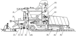
figure 1 is a front view of the solution of the utility model.
Fig. 2 is a rear view of the inventive arrangement.
Fig. 3 is a schematic structural diagram of the mineral aggregate transferring system in the scheme of the utility model.
Description of the reference numerals:
1-a frame; 2-an internal combustion engine; 3-a transfer case; 4-a hydraulic system; 5, a gas path system; 6-circuitry;
7-control platform and control system; 8-pushing a roller;
9-a blade pushing device;
91-pushing shovel support; 92-a shovel plate; 93-a blade lifting mechanism; 94-push shovel lengthening support;
95-a push shovel support rod; 96-pushing shovel support rod seat;
10-a walking device; 11-a receiving hopper;
12-a mineral aggregate transport system;
125-mineral aggregate conveying and lifting device;
1251-feeding hole of mineral aggregate conveying and lifting device; 1252-discharge port of mineral aggregate conveying and lifting device;
123-mineral aggregate caching bin;
1231-discharge port of mineral aggregate buffer storage bin; 1232-hopper gate;
124-mineral aggregate conveying device IV;
1241-a discharge hole of an ore material conveying device IV; 1242-a feed inlet of an ore material conveying device IV;
13-a waterway transfer system;
131-a water supply pump; 132-a cache water tank; 133-a feed pump; 134-movable water supply pump;
14-a bitumen transfer system;
141-feed asphalt pump; 142-a bitumen cache tank; 143-feed asphalt pump;
144-mobile feed asphalt pump;
15-powder additive addition system; 16-liquid additive addition system; 17-a bitumen spraying device;
18-a stirring device; 19-a spreading device; 20-a generator set; 21-a milling and brushing device; 22-a flushing device;
23-a fiber addition device; 24-a distributor; 25-sunscreen shed.
Detailed Description
The utility model is further described below with reference to the accompanying drawings:
example 1
As shown in figures 1 and 2, the micro-surfacing paver comprises a frame-1, an internal combustion engine-2, a transfer case-3, a hydraulic system-4, a gas circuit system-5, a circuit system-6, an operation platform and control system-7, a push roller-8, a push shovel device-9, a traveling device-10, a receiving hopper-11, a mineral aggregate transferring system-12, a water path transferring system-13, an asphalt transferring system-14, a powder additive adding system-15, a liquid additive adding system-16, an asphalt spraying device-17, a stirring device-18, a paving device-19 and a generator set-20. The left side and the right side of the bottom of the frame-1 are symmetrically provided with a walking device-10 in parallel, and a power assembly fixed in the rear part of the frame-1 above the walking device-10 is provided with an internal combustion engine-2 and a transfer case-3 which provide sufficient power for each functional mechanism of the equipment; the power input port of the transfer case-3 is connected with the power output port of the crankshaft of the internal combustion engine-2 in a transmission way, the power of the internal combustion engine-2 is reasonably distributed to functional parts by the specially designed transfer case-3, and each power output port of the transfer case-3 is connected with a hydraulic pump matched with each function in a transmission way so as to drive functional parts such as a hydraulic motor, a hydraulic oil cylinder and the like. The front end of the frame-1 is provided with a pushing roller-7 for pushing the rear tire of the mineral aggregate conveying vehicle to move ahead synchronously. A receiving hopper-11 is hinged above the front part of the frame-1. The space positions of the lower side of the receiving hopper-11 and the rear side of the receiving hopper-11, the front side of the internal combustion engine-2 and the upper side of the internal combustion engine-2 are provided with a mineral material transferring system-12, and a feed inlet of the mineral material transferring system-12 (namely a feed inlet-1211 of a mineral material conveying device I) is communicated with the lower part of the receiving hopper-11. A water path transferring system-13 and an asphalt transferring system-14 are arranged at the space positions of the front side and the upper side of the internal combustion engine-2 and the two sides of the mineral aggregate transferring system-12; the asphalt pump and the water pump can be respectively arranged on one side or can be arranged on both sides in a mixing way, the emulsified asphalt and the water are continuously, quantitatively and stably transferred to the stirring device-18 by the water path transfer system-13 and the emulsified asphalt transfer system-14, and simultaneously, the requirements of minimally invasive milling, water spraying and asphalt spraying are continuously, quantitatively and stably ensured. A stirring device-18 is arranged in the middle of the rear side of the frame-1, and a discharge hole of the mineral aggregate transferring system (a discharge hole-1241 of the mineral aggregate conveying device IV) is arranged right above and communicated with a feed hole-181 of the stirring device. The powder additive adding system-15 and the liquid additive adding system-16 are arranged above the rear side of the frame-1 and the stirring device-18, and the discharge port-151 of the powder additive adding system is above and communicated with the feed port-181 of the stirring device. The control platform and the control system-7 are arranged at the rear side of the frame and at the upper side or the right side or the left side of the stirring device-18. A spreading device-19 is arranged below a material distributing hopper, namely a discharge port-182 of a stirring device, and the spreading device-19 and a host machine of a micro-surfacing spreading machine adopt a pulling type chain flexible connection or pull rod hard connection mode. The spreading device-19 can be different types of spreading devices of different manufacturers; when cold-mixing cold-paving and in-situ cold-recycling or field-mixing cold-recycling paving construction operations are carried out, a conventional asphalt concrete paver screed is selected and installed.
Example 2
As shown in FIGS. 1 and 2, the blade device-9 is preferably bolted or mounted in a quick-release manner under the front of the frame-1 and under the push roller-8 and in front of the running gear-10, or under the rear of the frame-1 and behind the running gear-10, or between the middle of the frame-1 and the front and rear running gears of the running gear-10, such as between the front and rear wheels; the method realizes that mineral aggregate and other useless objects scattered in the construction process are quickly pushed to two sides of the pavement to be constructed.
As shown in fig. 1 and 2, the blade pushing device-9 comprises a blade pushing bracket-91 and a blade-92, wherein the blade-92 is mounted on the blade pushing bracket-91.
As shown in fig. 1 and 2, the blade pushing device-9 is designed with a lifting mechanism-93, which uses an oil cylinder and a link mechanism to enable the blade support to float up and down, so as to drive the lower edge of the blade to linearly contact and leave the road surface.
As shown in FIGS. 1 and 2, the blade assembly-9 includes a blade extension bracket-94 and a blade support rod-95. The shovel lengthened bracket-94 is fixedly connected with the shovel bracket-91 by adopting a quick detachable bolt; one end of the shovel supporting rod-95 is hinged with the shovel lengthening support-94, and the other end is hinged with the walking device-10 or a shovel supporting rod seat-96 on the frame-1 and used for supporting the lengthening part of the shoveling device-9. The shovel plate is arranged on the shovel lengthening support-94.
As shown in figures 1 and 2, the effective working width, namely the required lengthening distance, of the push shovel device-9 in the construction operation is matched with the paving width, and flexible splicing is realized. Shovel plates fixed by the shovel device bracket are bilaterally symmetrical to form an included angle on the central axis of the frame-1, and the arrow-shaped shovel plates are beneficial to pushing and discharging materials to two sides in the construction process; or the shovel plate shape straight line fixed by the pushing device bracket forms a small included angle with the central axis of the frame-1 as far as possible, namely the straight line is inclined, so that the pushing and discharging of the material are facilitated in the construction process; or the shovel plate fixed by the bracket of the blade pushing device is shaped to be vertical to the central axis of minus 1 in the frame in a straight line, and the shovel is similar to a bulldozer blade and pushes the scattered mineral aggregate and other useless objects forwards to be collected and cleaned regularly.
Example 3
As shown in figures 1, 2 and 3, the mineral aggregate transferring system-12 comprises a mineral aggregate conveying and lifting device-125, a mineral aggregate buffer bin-123 and a mineral aggregate conveying device IV-124. The mineral aggregate conveying and lifting device has I-level parallel conveying and II-level lifting of mineral aggregates, a mineral aggregate caching bin completes III-level mineral aggregate caching, a mineral aggregate conveying device IV achieves IV-level parallel conveying functions, and the mineral aggregate conveying device IV is matched with the mineral aggregate conveying device IV to convey the mineral aggregates in the receiving hopper-11 to the stirring device-18. The mineral aggregate conveying and lifting device-125 is arranged at the space position of the lower side and the rear side of the receiving hopper-11 and the front side of the internal combustion engine-2, and a feeding hole-1251 of the mineral aggregate conveying and lifting device (namely a feeding hole of the mineral aggregate transferring system-12) is communicated with a discharging hole of the receiving hopper-11. The mineral aggregate buffer bin-123 is arranged below the mineral aggregate conveying and lifting device discharge port-1252. The mineral aggregate conveying device IV-124 is arranged at a space position between the lower side of the mineral aggregate buffering bin-123 and the upper side of the internal combustion engine-2, a discharge hole-1231 of the mineral aggregate buffering bin is communicated with a feed hole-1242 of the mineral aggregate conveying device IV, and a discharge hole-1241 of the mineral aggregate conveying device IV (namely a discharge hole of the mineral aggregate transferring system-12) is arranged above and communicated with a feed hole-181 of the stirring device.
As shown in fig. 1, 2 and 3, the mineral aggregate conveying system-12 is designed with a mineral aggregate transferring metering and mineral aggregate conveying amount regulating device. Metering sensors are respectively arranged in the mineral aggregate conveying and lifting device-125, the mineral aggregate caching bin-123 and the mineral aggregate conveying device IV-124. The mineral aggregate conveying and lifting device-125 and the mineral aggregate conveying device IV-124 are used for cooperatively and coordinately controlling the conveying capacity of the mineral aggregate conveying system-12 through the regulation and control of the rotating speed of a variable hydraulic motor or a variable hydraulic pump. A hopper door-1232 is further arranged at the bottom of one side surface of the mineral aggregate buffering bin-123, namely one side of the conveying device IV-124 in the belt feeding direction; the opening degree of the hopper door can be adjusted up and down in a stepless mode, the rotating speed of the belt conveyor of the IV-124 conveying device can be adjusted in a stepless mode, and the feeding amount and the metering precision of the mineral aggregate conveying system-12 can be cooperatively changed.
As shown in fig. 3, the mineral aggregate transferring and lifting device-125 performs the functions of parallel and lifting transferring of the mineral aggregate at the same time. The mineral aggregate conveying and lifting device-125 is preferably a hopper type lifting conveyor, and can also be a belt type lifting conveyor, a lifting scraper conveyor or a chain belt (combination of a chain and a belt) type lifting conveyor. The driving chain wheel shaft or the driving belt roller shaft of the mineral aggregate conveying and lifting device-125 is in transmission connection with a mineral aggregate conveying and lifting speed reducer, the mineral aggregate conveying and lifting speed reducer is in transmission connection with a mineral aggregate conveying and lifting hydraulic motor, and the mineral aggregate conveying and lifting hydraulic motor is driven by a hydraulic pump in transmission connection with the transfer case.
Example 4
As shown in fig. 3, the mineral aggregate buffering bin-123 preferably uses a rectangular square hopper type hopper, the upper part is large, the lower part is small, the upper part is a feeding hole, and the lower part is a discharging hole; a sieve is arranged in the upper part of the mineral aggregate buffering bin and used for sieving and filtering mineral aggregates with super grain diameters, and a vibrating beam is arranged in the lower part of the mineral aggregate buffering bin to ensure smooth blanking; and a hopper door-1232 is arranged on the side surface of the mineral aggregate caching bin, namely one side of the mineral aggregate conveying device IV-124 in the belt feeding direction, and the opening and closing degree of the hopper door-1232 can be adjusted up and down in a stepless mode.
Example 5
As shown in FIG. 3, the mineral aggregate conveying device IV-124 is preferably a belt conveyor, and can also be a chain scraper conveyor or a chain slat conveyor or a continuous conveyor or a spiral conveyor; the driving belt roller shaft or the chain wheel shaft or the spiral shaft of the mineral aggregate conveying device IV-124 is in transmission connection with a mineral aggregate conveying speed reducer, the speed reducer of the mineral aggregate conveying device IV-124 is in transmission connection with a mineral aggregate conveying hydraulic motor, and the mineral aggregate conveying device IV hydraulic motor is driven by a matched hydraulic pump in transmission connection with the transfer case-3.
Example 6
As shown in fig. 1 and fig. 2, the receiving hopper-11 is hinged on the upper side of the front part of the frame-1, and is composed of two hopper components which are symmetrical left and right to form a receiving hopper; the left side hopper and the right side hopper of the receiving hopper-11 can be flexibly opened and closed through a hydraulic oil cylinder to enable mineral aggregate to leak smoothly.
Example 7
As shown in fig. 1 and 2, the micro-surfacing paver further comprises a generator set-20, wherein the generator set-20 is used for providing power current, lighting current, electric heating current and the like. Can output alternating current or direct current, and the voltage of 110V, 220V, 330V and the like; used for driving the feeding and feeding asphalt pump motor, the water supply pump and the water feeding pump motor, the mobile asphalt pump motor and the mobile water pump motor; an electric motor which can also be used to drive the mineral material conveying system (when the mineral material conveying system is driven by the electric motor); the device is used for providing power energy for heat preservation, heating and the like of the asphalt pipeline, the asphalt pump and the asphalt buffer tank.
Example 8
As shown in fig. 1 and 2, the micro-surfacing paver also includes a movable feed asphalt pump-144, a movable feed water pump-134. When asphalt and water are transferred to the asphalt buffer tank-142 and the buffer water tank-132, a submersible pump can be placed in a transport vehicle, and an outlet pipeline of the submersible pump is connected with an inlet of the buffer tank to transfer emulsified asphalt and water. The movable pump is provided with electric energy by the generator set-20 and is controlled by the control platform and the control system-7 in real time.
Example 9
The pipeline bracket is arranged on two sides of the micro-surfacing paver, the pipeline is suspended by the rope, and the rope suspension end can slide back and forth on the pipeline bracket. When water and asphalt in the water conveying and asphalt conveying vehicle are transferred to a buffer water tank and an asphalt buffer tank in a micro-surfacing paver, the water pipes and the asphalt conveying pipelines are hung on the pipeline bracket. The pipeline is supported in such a way, and the dragging effect on the pipeline caused by asynchronous stopping and starting of the equipment room is eliminated; when the speed of the equipment is different in the walking process, the dragging effect on the pipeline is buffered. Ensure the normal work of the conveying pipeline.
Example 10
As shown in FIGS. 1 and 2, the asphalt transferring system-14 comprises a feed asphalt pump-141, an asphalt buffer tank-142, a feed asphalt pump-143, an asphalt conveying pipeline, an asphalt flow meter, an asphalt pipeline valve and the like. The inlet and the outlet of the feeding asphalt pump-141 are respectively connected with an asphalt outlet of the emulsified asphalt conveying vehicle and an inlet pipeline of an asphalt buffer tank-142 and are used for conveying the emulsified asphalt on the asphalt conveying vehicle into the asphalt buffer tank-142; the asphalt buffer box-142 is used for buffering and storing enough emulsified asphalt; the inlet and the outlet of the feeding asphalt pump-143 are respectively connected with the asphalt buffer tank-142, the valve, the asphalt flow meter and the asphalt feed inlet pipeline of the stirring device-18, and the emulsified asphalt is metered and conveyed to the stirring device-18.
The green milk transferring system-14 is provided with an asphalt metering device, a liquid level sensor is arranged in an asphalt buffer tank-142, a variable asphalt pump is selected as a feeding asphalt pump-141 and a feeding asphalt pump-143, a variable hydraulic motor and a hydraulic pump or a variable frequency motor are selected, and the asphalt conveying amount, the metering and the precision control of the asphalt transferring system are cooperatively changed by adjusting the opening degree of an asphalt pipeline valve.
Example 11
As shown in fig. 1 and 2, the waterway transfer system-13 includes a water supply pump-131, a buffer water tank-132, a water supply pump-133, a water delivery pipe, a water flow meter, a water valve, and the like. The water inlet and outlet of the water supply pump-131 are respectively connected with the water outlet of the water delivery wagon and the water inlet of the buffer water tank-132, and are used for delivering the water on the delivery wagon into the buffer water tank-132. The buffer tank-132 is used to buffer and store a sufficient amount of water. The water inlet and the water outlet of the water feeding pump-133 are respectively connected with the cache water tank-132, the valve, the water flow meter and the water inlet pipeline of the stirring device-18, and water is metered and injected into the stirring device-18.
As shown in figures 1 and 2, the waterway transmission system-13 is provided with a water metering device, a buffer water tank-132 is provided with a liquid level sensor, a water supply pump-131 and a water supply pump-133 adopt a variable water pump, a variable hydraulic motor and a hydraulic pump or a variable frequency motor, and the water delivery quantity, the metering and the precision control of the waterway transmission system water are coordinated and changed by adjusting the opening degree of a valve of a water pipeline.
Example 11
As shown in fig. 1 and 2, the pushing roller-8 is arranged at the front end of the frame-1 of the micro-surfacing paver, and when the dump truck unloads materials to the receiving hopper, the pushing roller-8 pushes the rear tires of the dump truck to realize synchronous advance.
Example 13
As shown in figures 1 and 2, the running gear-10 is preferably a crawler type running gear, and can also be a wheel type running gear. The crawler-type traveling mechanism driving chain wheel or the wheel-type traveling mechanism wheel drum is in transmission connection with the traveling device-10 traveling speed reducer; the walking speed reducer is connected with the walking device-10 walking hydraulic motor in a transmission way and is driven by the walking hydraulic motor of the walking device driven by the walking hydraulic pump matched with the transfer case in the transmission way. The hydraulic system of the walking device is a closed system. The walking variable hydraulic motor, the variable hydraulic pump and the rotating speed sensor are selected to realize speed regulation. A hydraulic brake device is adopted.
Example 14
As shown in figures 1 and 2, the hydraulic system-4 is mainly formed by connecting a hydraulic pump, a hydraulic motor, a hydraulic oil cylinder and other execution components, an integrated valve block, a functional valve block, a sensor and a hydraulic pipeline, which are connected with each other in a transmission way, and have matched functions, and are connected with a power output port of the transfer case.
Example 15
As shown in fig. 1 and 2, the air path system-5 is formed by connecting an air compressor device, an air storage tank, an air cylinder and other execution components, an integrated valve block, a functional valve block, a sensor, an air pipe and the like. An air compressor is connected with the power take-off of the engine-2 in a transmission way to provide compressed air. The control system on the control platform controls the air cylinder in the punching and milling device-21 so as to realize the opening and closing of the water spray head; an air cylinder in the asphalt spraying device-17 further realizes the opening and closing of an asphalt spray head; the valve in the emulsified asphalt transferring system-14 is opened and closed, and the valve in the water path transferring system-13 is opened and closed.
Example 16
As shown in fig. 1 and 2, the control platform and control system-7 (including a control module cabinet) and the electrical control cabinet of the generator set-20 are arranged at the rear side of the frame-1 and at the upper side or the right side or the left side of the stirring device, and part of the electrical control module, the hydraulic control module and the gas circuit control module, and the circuit system are distributed at proper positions in different spaces of the body of the micro-surfacing paver. The control platform and the control system-7 carry out intelligent control and management on all functions of the micro-surfacing paver.
Example 17
As shown in FIGS. 1 and 2, the additive addition systems include a powder additive addition system-15 and a liquid additive addition system-16. The powder storage bin and the additive tank are arranged at the upper part of the rear side of the mineral aggregate buffering bin in the mineral aggregate transferring system.
Example 18
As shown in FIGS. 1 and 2, an asphalt spraying device-17 is disposed below the stirring device and in front of the spreading device-19. The method is used for preprocessing the sprayed asphalt on the road surface to be constructed before paving so as to enhance the adhesion between the paving layers. The asphalt buffer tank-142 in the asphalt melting and transferring system can be connected with a pipeline to spray emulsified asphalt, and an asphalt spraying bin can also be independently arranged to spray asphalt.
Example 19
As shown in FIGS. 1 and 2, the stirring device-18 is a two-shaft paddle type forced continuous differential stirring design.
Example 20
As shown in fig. 1 and 2, the paving device-19 is connected with the host machine of the micro-surfacing paving machine in a dragging manner, and the paving device-19 can be selected from micro-surfacing paving devices of different manufacturers and different types or rut paving devices to carry out micro-surfacing paving construction operation. When cold-mixing cold-paving and in-situ cold-recycling or field-mixing cold-recycling paving construction operation is required, the cold-mixing cold-paving and in-situ cold-recycling or field-mixing cold-recycling paving construction operation can be carried out by selecting and installing a screed of a conventional asphalt concrete paver without changing the structure and the system of equipment.
Example 21
As shown in fig. 1 and 2, a micro-surfacing paver further includes a "dry" pretreatment system, namely a minimally invasive milling and brushing apparatus-21. The minimally invasive milling and brushing device-21 is arranged below the stirring device-18 and behind the walking device-10. The cleaning brush is used for cleaning a road surface or carrying out minimally invasive fine milling and planing mechanical brushing on the road surface. The method improves the cleanliness of the pavement to be constructed, enhances the bonding force between paving surface layers, further improves the paving quality and reduces the occurrence of pavement diseases.
Example 22
As shown in fig. 1 and 2, a micro-surfacing paver also includes a "wet" pretreatment system, i.e., a die-milling device-22. The punching and milling device-22 is arranged below the stirring device-18 and behind the walking device-10. High-pressure water flow is adopted to carry out minimally invasive punching and milling on the surface layer of the road or spray water on the road surface so as to moisten and cool the road surface to be constructed. The method has the advantages that the cleanliness of the pavement to be constructed is improved, the temperature of the pavement is improved, the interlayer adhesive force of the paving surface is enhanced, the paving quality is improved, and the occurrence of pavement diseases is reduced.
In summary, compared with the existing slurry seal and micro-surfacing equipment, the micro-surfacing paver has the advantages that the slurry seal or micro-surfacing pavement quality paved by the micro-surfacing paver is remarkably improved. The excellent performance is shown as follows: the spreading construction operation can be completed at one time by integrating the process procedures of simultaneously receiving materials, carrying out minimally invasive pretreatment, namely, carrying out wet-type minimally invasive punching and milling dry-type minimally invasive milling and brushing, spraying asphalt, carrying out metering, carrying out batching, carrying out stirring, carrying out spreading, carrying out trowelling and the like. The system has the function of continuous construction operation or intermittent construction operation without other special supporting equipment. The innovative design of the 'dry' and 'wet' minimally invasive pretreatment devices is used for implementing the minimally invasive punching and milling and sweeping processes, and the effect of remarkably enhancing the adhesion force between pavement layers is perfectly realized. The device is easy and convenient to receive materials, simple and intelligent to operate and control, and capable of ingeniously improving the yield per unit time and reducing the production cost. The utility model effectively solves the problems of longitudinal and transverse joints and stub bars, and the phenomenon of different paving qualities in the same construction section due to the color difference phenomenon of pavement caused by different equipment and manipulators in construction. The utility model has high construction efficiency, large output per unit time, large paving width range and flexible setting and changing of the paving width. The pavement paving material has the advantages of high raw material proportioning precision, strong interlayer adhesive force, excellent and stable paving quality, reduction of pavement diseases, energy conservation, environmental protection and prolongation of the service life of the pavement. The utility model can carry out cold mixing and cold paving and in-situ cold recycling paving construction operation. The equipment and the construction method are suitable for construction in various operation surfaces and environments. The equipment utilization rate is high, and the whole process is used for paving construction operation and does not need to waste raw materials for transportation. The equipment disclosed by the utility model is compact, scientific and reasonable in structural layout, reliable in working performance, low in use and maintenance cost, high in cost performance and strong in popularization.
The above description is only a preferred embodiment of the present invention, and is not intended to limit the present invention, and all the simple modifications, changes, equivalent structural changes and construction method changes made by the technical essence of the present invention are still within the protection scope of the technical solution and method of the present invention.
Claims (10)
1. A micro-surfacing paver is characterized by comprising a rack (1), an internal combustion engine (2), a transfer case (3), a traveling device (10), a receiving hopper (11), a mineral aggregate transferring system (12), a water path transferring system (13), an asphalt transferring system (14), a circuit system and a stirring device (18); frame (1) lower part is provided with running gear (10) about, running gear (10) top with frame (1) rear portion internal fixation has internal-combustion engine (2) with transfer case (3), transfer case (3) with internal-combustion engine (2) transmission is connected transfer case (3) power delivery outlet transmission connects the hydraulic pump, frame (1) front portion top is provided with connect hopper (11), connect hopper (11) discharge gate with mineral aggregate is defeated system (12) feed inlet communicates with each other, mineral aggregate is defeated system (12) and is included I level parallel transport function, II level lifting function, III level mineral aggregate buffer memory function, IV level parallel transport function, mineral aggregate is defeated system (12) and is set up connect hopper (11) downside and rear side with internal-combustion engine (2) front side and upside, pitch is defeated system (14) with water route is defeated system (13) sets up mineral aggregate is defeated system (12) both sides and water route are defeated system (12) both sides and defeated The stirring device (18) is arranged in the middle of the rear side of the frame (1), and a discharge hole of the mineral aggregate transferring system (12) is arranged above a feed hole of the stirring device (18) and communicated with the feed hole.
2. The micro-surfacing spreading machine according to claim 1, further comprising a push shovel device (9), wherein the push shovel device (9) is used for pushing the scattered mineral aggregate and other materials to two sides of the road surface to be constructed, and the push shovel device (9) is arranged below the front part of the frame (1) and on the front side of the walking device (10); or is arranged below the rear part of the frame (1) and at the rear side of the walking device (10); or between the lower part of the middle part of the frame (1) and the front and rear walking devices (10).
3. The micro-surfacing spreading machine according to claim 2, wherein the push shovel device (9) comprises a push shovel bracket (91), a shovel plate (92), and a push shovel lifting mechanism (93), wherein the shovel plate (92) is installed on the push shovel bracket (91), and the push shovel lifting mechanism (93) drives the push shovel bracket (91) to float up and down to drive the shovel plate (92) to contact and leave with the road surface along the lower edge.
4. The micro-surfacing spreading machine according to claim 2, wherein the shovel device (9) comprises a shovel support (91), a shovel plate (92), a shovel lengthening support (94) and a shovel supporting rod (95), the shovel lengthening support (94) is detachably connected with the shovel support (91), one end of the shovel supporting rod (95) is connected with the other end of the shovel lengthening support (94) and is connected with a shovel supporting rod seat (96) for supporting a shovel device (9) lengthening part, and the shovel plate (92) is installed on the shovel lengthening support (94).
5. The micro-surfacing spreading machine according to claim 1, wherein the mineral aggregate transferring system (12) comprises a mineral aggregate conveying and lifting device (125), a mineral aggregate buffer bin (123) and a mineral aggregate conveying device IV (124), and realizes I-level parallel conveying, II-level lifting, III-level mineral aggregate buffer and IV-level parallel conveying, and jointly realizes transferring of the mineral aggregate in the receiving hopper (11) to the stirring device (18); the mineral aggregate conveying and lifting device (125) is arranged on the lower side and the rear side of the receiving hopper (11) and between the front sides of the internal combustion engine (2), a feed port of the mineral aggregate conveying and lifting device (125), namely a feed port of a mineral aggregate conveying system, is communicated with a discharge port of the receiving hopper (11), a mineral aggregate buffering bin (123) is arranged below the discharge port of the mineral aggregate conveying and lifting device (125) and is communicated with the discharge port of the internal combustion engine (2), a mineral aggregate conveying device IV (124) is arranged between the lower side of the mineral aggregate buffering bin (123) and the upper side of the internal combustion engine (2), a discharge port of the mineral aggregate buffering bin (123) is communicated with a feed port of the mineral aggregate conveying device IV (124), and a discharge port of the mineral aggregate conveying device IV (124), namely a discharge port of the mineral aggregate conveying system, is communicated with the upper side of the feed port of the stirring device (18).
6. The micro-surfacing spreading machine according to claim 1 or 5, wherein the mineral aggregate conveying and lifting device (125) performs I-level parallel conveying and II-level lifting conveying of mineral aggregates simultaneously, and the mineral aggregate conveying and lifting device (125) is a hopper type lifting conveyor; or a chain belt type lifting conveyor, or a lifting scraper conveyor, or a belt type lifting conveyor.
7. A micro-surfacing spreader according to claim 1, characterized in that the receiving hopper (11) is designed with opening and closing functions, and the receiving hopper (11) is hinged on the upper side of the front part of the frame (1).
8. A micro-surfacing paver according to claim 1, further comprising a generator set (20), the generator set (20) providing a source of motive energy.
9. The micro-surfacing paver of claim 1, further comprising a mobile feed water pump (134) and a mobile feed asphalt pump (144).
10. The micro-surfacing paver of claim 1, further comprising a pipe carriage.
Priority Applications (1)
| Application Number | Priority Date | Filing Date | Title |
|---|---|---|---|
| CN202121887434.XU CN216663711U (en) | 2021-08-13 | 2021-08-13 | Micro-surfacing paver |
Applications Claiming Priority (1)
| Application Number | Priority Date | Filing Date | Title |
|---|---|---|---|
| CN202121887434.XU CN216663711U (en) | 2021-08-13 | 2021-08-13 | Micro-surfacing paver |
Publications (1)
| Publication Number | Publication Date |
|---|---|
| CN216663711U true CN216663711U (en) | 2022-06-03 |
Family
ID=81757443
Family Applications (1)
| Application Number | Title | Priority Date | Filing Date |
|---|---|---|---|
| CN202121887434.XU Active CN216663711U (en) | 2021-08-13 | 2021-08-13 | Micro-surfacing paver |
Country Status (1)
| Country | Link |
|---|---|
| CN (1) | CN216663711U (en) |
Cited By (1)
| Publication number | Priority date | Publication date | Assignee | Title |
|---|---|---|---|---|
| CN113463477A (en) * | 2021-08-13 | 2021-10-01 | 李维维 | Micro-surfacing paver and construction method |
-
2021
- 2021-08-13 CN CN202121887434.XU patent/CN216663711U/en active Active
Cited By (1)
| Publication number | Priority date | Publication date | Assignee | Title |
|---|---|---|---|---|
| CN113463477A (en) * | 2021-08-13 | 2021-10-01 | 李维维 | Micro-surfacing paver and construction method |
Similar Documents
| Publication | Publication Date | Title |
|---|---|---|
| WO2020042285A1 (en) | Intelligent multipurpose segregation-resistance paver having large width and thickness | |
| CN216663710U (en) | Micro-surfacing paver | |
| CN106245506A (en) | Multifunction road regenerating device and pavement recycling construction method | |
| CN216663691U (en) | Synchronous chip seal paver | |
| CN105696448A (en) | Integrated asphalt road surface planing and milling repair vehicle | |
| CN106223179A (en) | Road surface hot recycling machine and road surface hot reproduction construction method | |
| CN113417193A (en) | Synchronous gravel seal layer paver and construction method | |
| AU2018250622A1 (en) | System for tracking operating time for conveyor of working machine | |
| CN113564987A (en) | Synchronous gravel seal layer paver and construction method | |
| CN216663711U (en) | Micro-surfacing paver | |
| CN201330367Y (en) | In-site warm mixing regeneration remixer for asphalt pavement | |
| CN101029469B (en) | Anti-segregation asphalt spreader with secondary agitation and temperature compensating functions | |
| CN109183583A (en) | It is layered hot milling equipment, the complete unit of the compound in-situ heat regeneration of hot wind and microwave and its construction in layer method | |
| CN201447656U (en) | Asphalt macadam synchronous layer sealing vehicle | |
| CN102912712B (en) | Cold-stirring and cold-paving all-in-one machine | |
| CN113463477A (en) | Micro-surfacing paver and construction method | |
| CN205420986U (en) | Integral type bituminous paving digs and mills restoration car | |
| CN216663692U (en) | Synchronous chip seal paver | |
| US3267824A (en) | Pavement laying apparatus | |
| CN216663694U (en) | Synchronous chip seal paver | |
| CN102828456B (en) | Agitator assembly | |
| CN216663688U (en) | Micro-surfacing paver | |
| CN113463478A (en) | Micro-surfacing paver and construction method | |
| CN103628418B (en) | A kind of mechanical construction method of steel deck ERS system | |
| CN214831675U (en) | Cement paste spraying vehicle |
Legal Events
| Date | Code | Title | Description |
|---|---|---|---|
| GR01 | Patent grant | ||
| GR01 | Patent grant |