CN216642803U - Radial dynamic pressure air bearing with reinforced damping effect - Google Patents
Radial dynamic pressure air bearing with reinforced damping effect Download PDFInfo
- Publication number
- CN216642803U CN216642803U CN202123136409.0U CN202123136409U CN216642803U CN 216642803 U CN216642803 U CN 216642803U CN 202123136409 U CN202123136409 U CN 202123136409U CN 216642803 U CN216642803 U CN 216642803U
- Authority
- CN
- China
- Prior art keywords
- bearing
- air bearing
- bearing seat
- gasket
- dynamic pressure
- Prior art date
- Legal status (The legal status is an assumption and is not a legal conclusion. Google has not performed a legal analysis and makes no representation as to the accuracy of the status listed.)
- Active
Links
Images


Classifications
-
- Y—GENERAL TAGGING OF NEW TECHNOLOGICAL DEVELOPMENTS; GENERAL TAGGING OF CROSS-SECTIONAL TECHNOLOGIES SPANNING OVER SEVERAL SECTIONS OF THE IPC; TECHNICAL SUBJECTS COVERED BY FORMER USPC CROSS-REFERENCE ART COLLECTIONS [XRACs] AND DIGESTS
- Y02—TECHNOLOGIES OR APPLICATIONS FOR MITIGATION OR ADAPTATION AGAINST CLIMATE CHANGE
- Y02E—REDUCTION OF GREENHOUSE GAS [GHG] EMISSIONS, RELATED TO ENERGY GENERATION, TRANSMISSION OR DISTRIBUTION
- Y02E10/00—Energy generation through renewable energy sources
- Y02E10/70—Wind energy
- Y02E10/72—Wind turbines with rotation axis in wind direction
Abstract
The utility model discloses a radial dynamic pressure air bearing with an enhanced damping effect, which comprises a bearing seat, a wave foil and a top foil which are sequentially assembled in a pre-tightening manner from outside to inside, wherein the wave foil is a corrugated elastic supporting component, the radial dynamic pressure air bearing also comprises a gasket positioned between the bearing seat and the wave foil, the gasket is of an open annular structure, a plurality of cantilever beams are arranged on the gasket in an array manner, after the radial dynamic pressure air bearing is arranged in the inner aperture of the bearing seat, the free ends of the cantilever beams are in contact with the bearing seat, and a gap is formed between the fixed ends and the bearing seat. The pad is provided with a support similar to a cantilever beam structure, and the pad is added to improve the damping effect of the bearing. After the cantilever beam is stressed, deformed and attached to the inner hole of the bearing seat, the corrugated foil can be continuously stressed and deformed when the cantilever beam cannot be further deformed, and therefore the overall bearing capacity of the bearing is improved.
Description
Technical Field
The utility model relates to the field of air bearings, in particular to a radial dynamic pressure air bearing with a damping strengthening effect.
Background
The radial dynamic pressure air bearing with the structure is simple in structure and convenient to process, so that the radial dynamic pressure air bearing with the traditional structure is widely applied to engineering, especially in the high-speed fluid machinery industries such as air suspension blowers, turbochargers and ACMs.
However, with the rapid development of the air floating industry, the related products in the air floating industry begin to develop towards high speed and even ultra high speed, and the rotation speed of hundreds of thousands of revolutions per minute or even hundreds of thousands of revolutions per minute is very frequent, so that higher and more severe requirements are provided for the design and use of the bearing. The radial dynamic pressure air bearing ensures that the shafting can stably run at each rotating speed within the range of 0-working rotating speed, and can timely consume the energy in the face of vibration and impact energy caused by the high-rotating-speed shafting so as to avoid the accumulation of the energy and the final instability and burning loss of the shafting.
In practical engineering application, it is found that for a low rotating speed, for example, within a rotating speed range of about 120000rpm and below, the conventional radial dynamic pressure air bearing can basically ensure the stable operation of a shaft system, but when a higher rotating speed is required, for example, 150000rpm or even 200000rpm, the conventional radial dynamic pressure air bearing often hardly meets the stable operation of the shaft system, even if the high rotating speed can be occasionally operated, a bearing surface has a large wear mark when the machine is stopped and dismounted, which is often the expression that the shaft system is unstable in operation and the shaft system vibrates greatly when the shaft system operates, so that the shaft system directly contacts with a radial top foil to cause wear. More seriously, the bump foil is deformed, and the bearing is burnt. The long-time running of the bearing shafting is not facilitated, so that the problem that needs to be solved is to ensure the stable running of the shafting and the long-time stable use of the bearing.
According to the current bearing-rotor dynamics theory, when a shaft system operates, a column vortex and a cone vortex are usually generated, which are the most main factors causing the shaft system to be incapable of stably operating. The shafting cannot operate stably, often because the bearings cannot provide enough damping to dissipate the impact vibration energy caused by the column vortex and the cone vortex. How do the bearing provide more damping? One seemingly feasible solution is to reduce the stiffness of the wave foil by changing the shape parameters of the wave arch, such as the wave arch radius, wave height, pitch, etc. The corrugated foil is easier to deform when being loaded, so that relative sliding is generated between the corrugated foil and the top foil and between the corrugated foil and the bearing seat, and the impact vibration energy of the shafting is consumed by friction generated by the sliding. However, if the hydrogen fuel cell is driven on the road after being mounted on a vehicle by an air compressor under certain conditions, for example, the hydrogen fuel cell is subjected to an irresistible external impact, the whole hydrogen fuel cell is inevitably subjected to an impact caused by road bumping, the impact is certainly transmitted to the bearing through the shaft system, the deformation degree of the corrugated foil exceeds elastic deformation to achieve plastic deformation, and the corrugated foil cannot recover to the original shape, so that the bearing is also failed.
Therefore, the structure of the radial bearing must be optimized and adjusted to ensure that the shafting can stably run at any designed rotating speed and can bear working conditions such as vibration impact and the like. There is a need to provide a new structure to meet the above requirements.
SUMMERY OF THE UTILITY MODEL
The utility model aims to solve the technical problem of providing a radial dynamic pressure air bearing which can ensure that a shaft system can stably run at any designed rotating speed and can bear working conditions such as vibration impact and the like and has a damping enhancement effect.
In order to solve the technical problems, the technical scheme adopted by the utility model is as follows:
radial dynamic pressure air bearing with strengthen damping effect includes that pretension is equipped with bearing frame, ripples paper tinsel and top paper tinsel in proper order from outer to interior, the ripples paper tinsel is corrugated elastic support component, its characterized in that still includes the liner that is located between bearing frame and the ripples paper tinsel, the liner is open-ended annular structure, has arranged a plurality of cantilever beams on the liner in array, adorns behind the bearing frame inner bore, the free end and the bearing frame contact of cantilever beam, has the clearance between stiff end and bearing frame.
The technical scheme is that after the cantilever beam is installed in the inner hole of the bearing seat, the cantilever beam and the gasket are arranged in a tangent mode.
The further technical scheme is that the free ends of the two circumferentially adjacent cantilever beams face opposite directions.
The further technical scheme is that 8-12 rows of cantilever beams are arranged in the axial direction of the pad.
The technical scheme is that two inclined slots are formed in the inner wall of the bearing seat, and two ends of the gasket are obliquely inserted into the inclined slots and can move along the inclined slots.
A further technical solution is that the pad is formed with a cantilever beam by etching or laser cutting. .
Adopt the produced beneficial effect of above-mentioned technical scheme to lie in:
the radial dynamic pressure air bearing of the present disclosure improves the damping effect of the bearing by adding a gasket. The liner is provided with a support similar to a cantilever beam structure, after the liner is arranged on the bearing seat, the free end of each small cantilever beam can be in contact with the inner hole of the bearing seat when the liner is not loaded, when the liner is loaded, not only can the bump foil be deformed or move relative to the bearing seat to provide friction damping, but also the cantilever beam structure can slide relative to the bearing seat to provide more friction damping so as to maintain the stable operation of the shafting. After the cantilever beam is stressed, deformed and attached to the inner hole of the bearing seat, the corrugated foil can continue to be stressed and deformed when the cantilever beam cannot be further deformed, and therefore the overall bearing capacity of the bearing is improved.
Drawings
The utility model is described in further detail below with reference to the drawings and the detailed description.
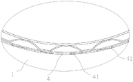
FIG. 1 is a schematic structural view of a radial hydrodynamic air bearing of the present disclosure;
FIG. 2 is an enlarged schematic view of portion A of FIG. 1;
FIG. 3 is a schematic view of the installed liner of the present disclosure;
FIG. 4 is a schematic view of the liner of the present disclosure prior to installation;
fig. 5 is a schematic structural view of a bearing housing of the present disclosure.
Detailed Description
The technical solutions in the embodiments of the present invention are clearly and completely described below with reference to the drawings in the embodiments of the present invention, and it is obvious that the described embodiments are some, not all, embodiments of the present invention. All other embodiments, which can be derived by a person skilled in the art from the embodiments given herein without making any creative effort, shall fall within the protection scope of the present invention.
In the following description, numerous specific details are set forth in order to provide a thorough understanding of the present invention, but the present invention may be practiced in other ways than those specifically described and will be readily apparent to those of ordinary skill in the art without departing from the spirit of the present invention, and therefore the present invention is not limited to the specific embodiments disclosed below.
As shown in fig. 1 to 5, the radial dynamic pressure air bearing with enhanced damping effect comprises a bearing seat 1, a wave foil 2 and a top foil 3 which are sequentially assembled from outside to inside in a pre-tightening manner, wherein the wave foil 2 is a corrugated elastic supporting member, a straight slot 11 is formed in the inner wall of the bearing seat 1, and the fixed ends of the wave foil 2 and the top foil 3 are inserted into the straight slot 11. The radial dynamic pressure air bearing of the present disclosure further comprises a gasket 4 located between the bearing seat 1 and the bump foil 2, wherein the gasket 4 is an open ring structure, two inclined slots 12 are formed in the inner wall of the bearing seat 1, and two ends of the gasket 4 are obliquely inserted into the inclined slots 12 and can move along the inclined slots 12.
A plurality of cantilever beams 41 are arranged on the gasket 4 in an array mode, after the cantilever beams are installed in the inner bore of the bearing seat, the free ends of the cantilever beams 41 are in contact with the bearing seat 1, and a gap is reserved between the fixed ends and the bearing seat 1.
Preferably, after the gasket 4 is installed in the inner bore of the bearing seat, the cantilever beam 41 is arranged tangentially to the gasket 4, so as to ensure the stability of the connection between the fixed end of the cantilever beam 41 and the gasket 4.
The cantilever beam 41 may be formed by welding on the pad 4, but for the convenience of processing the cantilever beam 41, it is preferable to etch or laser cut the pad 4, that is, the pad 4 and the cantilever beam 41 are in an integral structure, and the pad 4 has a notch for accommodating the cantilever beam 41, and the cantilever beam 41 can be deformed to be inserted into the notch after the bearing is loaded, so that the pad 4 is entirely contacted with the inner ring of the bearing seat 1. Before being assembled to the bearing seat 1, the bearing seat is in a flattening state, namely, the bearing seat is not required to be rolled and formed, and when the bearing seat is used, the bearing seat is directly assembled to the inner hole diameter of the bearing seat 1.
The radial dynamic pressure air bearing of the present disclosure improves the damping effect of the bearing by adding the spacer 4. The spacer 4 has a support similar to the cantilever beam 41 structure, and when the bearing seat 1 is installed, the free end of each small cantilever beam 41 will contact the inner hole of the bearing seat 1 when not under load, and when under load, not only will the bump foil 2 deform or move relative to the bearing seat 1 to provide friction damping, but also the cantilever beam 41 structure will slide relative to the bearing seat 1 to provide more friction damping to maintain the stable operation of the shafting. After the cantilever beam 41 is stressed, deformed and attached to the inner hole of the bearing seat 1, the wave foil 2 can continue to be stressed and deformed when the cantilever beam cannot be further deformed, and therefore the integral bearing capacity of the bearing is improved.
The free ends of two circumferentially adjacent cantilever beams 41 face opposite directions, and the stability of the shafting is improved through the crossed layout of the cantilever beams 41. 8-12 rows of cantilever beams 41 are arranged in the axial direction of the gasket 4 and distributed in a multi-point mode, and the deformation capacity is high.
The above is only a preferred embodiment of the utility model, and any simple modifications, variations and equivalents of the utility model may be made by anyone in light of the above teachings and fall within the scope of the utility model.
Claims (6)
1. Radial dynamic pressure air bearing with strengthen damping effect, include from outer to interior pretension in proper order and be equipped with bearing frame (1), ripples paper tinsel (2) and top paper tinsel (3), ripples paper tinsel (2) are corrugated elastic support component, its characterized in that, still including being located liner (4) between bearing frame (1) and ripples paper tinsel (2), liner (4) are open-ended annular structure, and array arrangement has a plurality of cantilever beams (41) on liner (4), adorns behind the bearing frame inner bore, the free end and the bearing frame (1) contact of cantilever beam (41), have the clearance between stiff end and bearing frame (1).
2. Radial hydrodynamic air bearing according to claim 1, characterized in that the cantilevered beams (41) are arranged tangentially to the pad (4) after fitting into the bore of the housing.
3. A radial hydrodynamic air bearing according to claim 1, characterized in that the free ends of two circumferentially adjacent cantilever beams (41) are oppositely directed.
4. The radial hydrodynamic air bearing according to claim 1, characterized in that the gasket (4) has 8 to 12 rows of cantilever beams (41) in the axial direction.
5. The radial hydrodynamic air bearing according to claim 1, wherein the bearing housing (1) has two inclined insertion grooves (12) on the inner wall thereof, and the gasket (4) has both ends inserted into the inclined insertion grooves (12) in an inclined manner and is movable along the inclined insertion grooves (12).
6. Radial hydrodynamic air bearing, according to claim 1, characterized in that the gasket (4) is formed with cantilever beams (41) by etching or laser cutting.
Priority Applications (1)
| Application Number | Priority Date | Filing Date | Title |
|---|---|---|---|
| CN202123136409.0U CN216642803U (en) | 2021-12-13 | 2021-12-13 | Radial dynamic pressure air bearing with reinforced damping effect |
Applications Claiming Priority (1)
| Application Number | Priority Date | Filing Date | Title |
|---|---|---|---|
| CN202123136409.0U CN216642803U (en) | 2021-12-13 | 2021-12-13 | Radial dynamic pressure air bearing with reinforced damping effect |
Publications (1)
| Publication Number | Publication Date |
|---|---|
| CN216642803U true CN216642803U (en) | 2022-05-31 |
Family
ID=81741117
Family Applications (1)
| Application Number | Title | Priority Date | Filing Date |
|---|---|---|---|
| CN202123136409.0U Active CN216642803U (en) | 2021-12-13 | 2021-12-13 | Radial dynamic pressure air bearing with reinforced damping effect |
Country Status (1)
| Country | Link |
|---|---|
| CN (1) | CN216642803U (en) |
Cited By (1)
| Publication number | Priority date | Publication date | Assignee | Title |
|---|---|---|---|---|
| CN116838723A (en) * | 2023-09-04 | 2023-10-03 | 天津飞旋科技股份有限公司 | Bearing body, foil hydrodynamic bearing and rotary machine shafting |
-
2021
- 2021-12-13 CN CN202123136409.0U patent/CN216642803U/en active Active
Cited By (2)
| Publication number | Priority date | Publication date | Assignee | Title |
|---|---|---|---|---|
| CN116838723A (en) * | 2023-09-04 | 2023-10-03 | 天津飞旋科技股份有限公司 | Bearing body, foil hydrodynamic bearing and rotary machine shafting |
| CN116838723B (en) * | 2023-09-04 | 2023-11-03 | 天津飞旋科技股份有限公司 | Bearing body, foil hydrodynamic bearing and rotary machine shafting |
Similar Documents
| Publication | Publication Date | Title |
|---|---|---|
| CN216642803U (en) | Radial dynamic pressure air bearing with reinforced damping effect | |
| EP3299643B1 (en) | Mixed-type dynamic pressure gas radial bearing | |
| CN111577765B (en) | Static pressure type radial gas bearing structure | |
| KR20100045253A (en) | Hybrid air foil journal bearings with external hydrostatic pressure supplies | |
| CN215762786U (en) | Gas thrust bearing, compressor and air conditioning system | |
| CN110566572B (en) | Variable air gap foil bearing and high-speed motor | |
| CN214788551U (en) | Radial foil dynamic pressure air bearing with good damping effect | |
| CN214788550U (en) | Radial foil dynamic pressure air bearing capable of improving stable operation capability of shafting | |
| CN214331181U (en) | Integrated elastic foil dynamic pressure air bearing | |
| CN113719530A (en) | Gas thrust bearing, compressor and air conditioning system | |
| CN213088509U (en) | Multi-positioning radial foil hydrodynamic air bearing | |
| CN114198391B (en) | Air-float radial bearing | |
| CN201827242U (en) | Annular roller bearing | |
| CN217558561U (en) | Bearing body assembly structure of multistage centrifugal pump | |
| CN212028330U (en) | Radial foil bearing with optimized top foil stiffness distribution | |
| CN111075878A (en) | End surface stepped groove rotary sealing ring | |
| CN215908074U (en) | Air compressor rotor assembly | |
| CN216642802U (en) | Radial dynamic pressure air bearing with multi-section non-uniform corrugated foils | |
| KR102218462B1 (en) | Air foil journal bearing | |
| CN113503319A (en) | Wave foil combined type radial air bearing device | |
| CN215950142U (en) | Suspension shaft assembly, motor, compressor, air conditioner and refrigerator | |
| CN219570610U (en) | Multistage pre-tightening radial dynamic pressure air bearing | |
| CN213393144U (en) | Retainer, bearing and jaw crusher | |
| CN217873806U (en) | Gas dynamic pressure radial bearing | |
| CN211398266U (en) | Dynamic pressure gas radial bearing and power equipment |
Legal Events
| Date | Code | Title | Description |
|---|---|---|---|
| GR01 | Patent grant | ||
| GR01 | Patent grant |