CN216635280U - Vertical injection molding machine with guide structure - Google Patents
Vertical injection molding machine with guide structure Download PDFInfo
- Publication number
- CN216635280U CN216635280U CN202122901930.2U CN202122901930U CN216635280U CN 216635280 U CN216635280 U CN 216635280U CN 202122901930 U CN202122901930 U CN 202122901930U CN 216635280 U CN216635280 U CN 216635280U
- Authority
- CN
- China
- Prior art keywords
- fixedly connected
- injection molding
- molding machine
- cooling
- heat dissipation
- Prior art date
- Legal status (The legal status is an assumption and is not a legal conclusion. Google has not performed a legal analysis and makes no representation as to the accuracy of the status listed.)
- Expired - Fee Related
Links
- 238000001746 injection moulding Methods 0.000 title claims abstract description 32
- 238000001816 cooling Methods 0.000 claims abstract description 35
- 238000002347 injection Methods 0.000 claims abstract description 17
- 239000007924 injection Substances 0.000 claims abstract description 17
- 230000017525 heat dissipation Effects 0.000 claims description 18
- 230000000149 penetrating effect Effects 0.000 claims description 7
- XLYOFNOQVPJJNP-UHFFFAOYSA-N water Substances O XLYOFNOQVPJJNP-UHFFFAOYSA-N 0.000 abstract description 10
- 238000009434 installation Methods 0.000 abstract description 3
- 238000004519 manufacturing process Methods 0.000 abstract description 3
- 239000000110 cooling liquid Substances 0.000 abstract 2
- 239000004033 plastic Substances 0.000 description 14
- 229920003023 plastic Polymers 0.000 description 14
- 238000000465 moulding Methods 0.000 description 13
- 239000002826 coolant Substances 0.000 description 6
- 239000007788 liquid Substances 0.000 description 6
- 239000000243 solution Substances 0.000 description 6
- 241000883990 Flabellum Species 0.000 description 3
- 238000004378 air conditioning Methods 0.000 description 2
- 238000007664 blowing Methods 0.000 description 2
- 239000002994 raw material Substances 0.000 description 2
- 238000007493 shaping process Methods 0.000 description 2
- 230000009286 beneficial effect Effects 0.000 description 1
- 230000033228 biological regulation Effects 0.000 description 1
- 230000007547 defect Effects 0.000 description 1
- 238000010586 diagram Methods 0.000 description 1
- 238000007599 discharging Methods 0.000 description 1
- 230000000694 effects Effects 0.000 description 1
- 239000000463 material Substances 0.000 description 1
- 238000000034 method Methods 0.000 description 1
- 238000012986 modification Methods 0.000 description 1
- 230000004048 modification Effects 0.000 description 1
- 238000010137 moulding (plastic) Methods 0.000 description 1
- 239000011148 porous material Substances 0.000 description 1
- 230000001737 promoting effect Effects 0.000 description 1
- 238000005057 refrigeration Methods 0.000 description 1
- 229920001169 thermoplastic Polymers 0.000 description 1
- 229920001187 thermosetting polymer Polymers 0.000 description 1
Images

Classifications
-
- Y—GENERAL TAGGING OF NEW TECHNOLOGICAL DEVELOPMENTS; GENERAL TAGGING OF CROSS-SECTIONAL TECHNOLOGIES SPANNING OVER SEVERAL SECTIONS OF THE IPC; TECHNICAL SUBJECTS COVERED BY FORMER USPC CROSS-REFERENCE ART COLLECTIONS [XRACs] AND DIGESTS
- Y02—TECHNOLOGIES OR APPLICATIONS FOR MITIGATION OR ADAPTATION AGAINST CLIMATE CHANGE
- Y02P—CLIMATE CHANGE MITIGATION TECHNOLOGIES IN THE PRODUCTION OR PROCESSING OF GOODS
- Y02P70/00—Climate change mitigation technologies in the production process for final industrial or consumer products
- Y02P70/10—Greenhouse gas [GHG] capture, material saving, heat recovery or other energy efficient measures, e.g. motor control, characterised by manufacturing processes, e.g. for rolling metal or metal working
Landscapes
- Moulds For Moulding Plastics Or The Like (AREA)
- Injection Moulding Of Plastics Or The Like (AREA)
Abstract
The utility model discloses a vertical injection molding machine with a guide structure, which comprises an installation seat, wherein the top of the installation seat is fixedly connected with two supporting rods, the top of each supporting rod is fixedly connected with a limiting plate, a pushing transverse plate is movably sleeved between the outer side walls of the two supporting rods, the bottom of the limiting plate is fixedly connected with an electric telescopic rod, the piston end of the electric telescopic rod is fixedly connected with the pushing transverse plate, and the bottom of the pushing transverse plate is fixedly connected with an injection upper mold. According to the utility model, the water pump can drive the cooling pipe to extract the cooling liquid in the cooling box by utilizing the cooling circulation component, so that the cooling liquid can conveniently flow into the snake-shaped hose through the connecting pipe, and then is conducted and cooled through the snake-shaped hose, so that the cold air can cool the injection lower mold, and meanwhile, the fan blades are adjusted to blow the snake-shaped hose, so that the air is cooled, thus the cooling speed of the mold in the injection lower mold is increased, the mold is easy to form, and the production efficiency is improved.
Description
Technical Field
The utility model relates to the technical field of injection molding machines, in particular to a vertical injection molding machine with a guide structure.
Background
An injection molding machine, also known as an injection molding machine or an injection machine, is a main molding apparatus for molding thermoplastic plastics or thermosetting materials into plastic products of various shapes using a plastic molding die, and a vertical injection molding machine is a type of injection molding machine.
At present, in the actual use process, the injection molding of the existing partial vertical injection molding machine is not ideal, so that the temperature of an injection mold is too high during injection molding, the injection mold is not easy to form, and the production efficiency is reduced.
SUMMERY OF THE UTILITY MODEL
The utility model aims to solve the defects in the prior art and provides a vertical injection molding machine with a guide structure.
In order to achieve the purpose, the utility model adopts the following technical scheme: a vertical injection molding machine with a guide structure comprises a mounting seat, wherein two supporting rods are fixedly connected to the top of the mounting seat, a limiting plate is fixedly connected to the top of each supporting rod, a pushing transverse plate is movably sleeved between the outer side walls of the two supporting rods, an electric telescopic rod is fixedly connected to the bottom of the limiting plate, the piston end of the electric telescopic rod is fixedly connected with the pushing transverse plate, an injection upper mold is fixedly connected to the bottom of the pushing transverse plate, a feeding hose is fixedly connected to the side wall of the injection upper mold, a first electromagnetic valve is fixedly connected to the side wall of the feeding hose, a mounting groove is formed in the top of the mounting seat, a connecting groove is formed in the bottom of the mounting groove, an air outlet assembly is fixedly arranged at the bottom of the connecting groove inner cavity, an adjusting spring is fixedly connected to the tail end of the adjusting spring, an injection lower mold is fixedly connected to the top of the radiating shell, and the top of the mounting seat is fixedly connected with a cooling circulation assembly.
As a further description of the above technical solution:
the air outlet assembly comprises an adjusting motor fixedly connected with the bottom of the inner cavity of the connecting groove, and an output shaft of the adjusting motor is fixedly connected with an adjusting fan blade.
As a further description of the above technical solution:
the refrigeration cycle subassembly include with mount pad top fixed connection's cooler bin, cooler bin lateral wall fixedly connected with cooling tube, the terminal fixedly connected with suction pump of cooling tube, suction pump delivery port fixedly connected with connecting pipe, heat dissipation shell inner wall fixedly connected with snakelike hose, the connecting pipe is terminal to be connected with snakelike hose, snakelike hose end run through the heat dissipation shell and with cooler bin fixed connection, cooler bin lateral wall fixedly connected with flow pipe, flow pipe lateral wall fixedly connected with second solenoid valve.
As a further description of the above technical solution:
a plurality of first holes are formed in the top of the heat dissipation shell in a penetrating mode, and a plurality of second holes are formed in the bottom of the heat dissipation shell in a penetrating mode.
As a further description of the above technical solution:
a plurality of air inlets are arranged at the bottom of the mounting seat in a penetrating manner.
As a further description of the above technical solution:
and an injection molding opening is formed in the top of the injection molding lower die.
The utility model has the following beneficial effects:
through the cooperation between air-out subassembly and the cooling cycle subassembly, utilize the air-out subassembly to make the adjusting motor drive the regulation flabellum rotate, be convenient for carry out the cooling of blowing to the lower mould of moulding plastics, utilize the cooling cycle subassembly to make the suction pump drive the cooling tube and extract the inside coolant liquid of cooler bin, the coolant liquid of being convenient for flows in snakelike hose through the connecting pipe, thereby through snakelike hose conduction cooling, make air conditioning cool off the lower mould of moulding plastics, adjust the flabellum simultaneously and blow to snakelike hose, make wind meet cold, thereby accelerate the inside mould cooling rate of lower mould of moulding plastics, make the mould shaping easily, and the production efficiency is improved.
Drawings
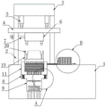
FIG. 1 is a schematic overall structure diagram of a vertical injection molding machine with a guide structure according to the present invention;
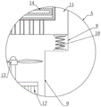
FIG. 2 is an enlarged schematic view of the structure at A in FIG. 1;
fig. 3 is an enlarged schematic structural view at B in fig. 1.
Illustration of the drawings:
1. a mounting seat; 2. a support bar; 3. a limiting plate; 4. pushing the transverse plate; 5. an electric telescopic rod; 6. injection molding an upper mold; 7. a feeding hose; 8. mounting grooves; 9. connecting grooves; 10. adjusting the spring; 11. a heat dissipation housing; 12. adjusting the motor; 13. adjusting the fan blades; 14. a serpentine hose; 15. a water pump; 16. a cooling tube; 17. a cooling tank; 18. a water supply pipe; 19. injection molding a lower mold; 20. and (7) injection molding of the opening.
Detailed Description
The technical solutions in the embodiments of the present invention will be clearly and completely described below with reference to the drawings in the embodiments of the present invention, and it is obvious that the described embodiments are only a part of the embodiments of the present invention, and not all of the embodiments. All other embodiments, which can be derived by a person skilled in the art from the embodiments given herein without making any creative effort, shall fall within the protection scope of the present invention.
Referring to fig. 1-3, the utility model provides a vertical injection molding machine with a guide structure, comprising a mounting seat 1, a plurality of air inlets are arranged at the bottom of the mounting seat 1 in a penetrating manner, two support rods 2 are fixedly connected to the top of the mounting seat 1, a limit plate 3 is fixedly connected to the top of each support rod 2, a push transverse plate 4 is movably sleeved between the outer side walls of the two support rods 2, an electric telescopic rod 5 is fixedly connected to the bottom of the limit plate 3, the piston end of the electric telescopic rod 5 is fixedly connected with the push transverse plate 4, an injection upper mold 6 is fixedly connected to the bottom of the push transverse plate 4, a feeding hose 7 is fixedly connected to the side wall of the injection upper mold 6, a first electromagnetic valve is fixedly connected to the side wall of the feeding hose 7, a mounting groove 8 is arranged at the top of the mounting seat 1, a connecting groove 9 is arranged at the bottom of the mounting groove 8, an air outlet assembly is fixed to the bottom of the inner cavity of the connecting groove 9, and plays a role of blowing through the air outlet assembly, referring to fig. 1, the air outlet assembly includes an adjusting motor 12 fixedly connected with the bottom of the inner cavity of the connecting groove 9, an output shaft of the adjusting motor 12 is fixedly connected with an adjusting fan blade 13, and the adjusting fan blade 13 is driven to rotate by the adjusting motor 12.
An adjusting spring 10 is fixed at the bottom of an inner cavity of the mounting groove 8, the tail end of the adjusting spring 10 is fixedly connected with a heat dissipation shell 11, the top of the heat dissipation shell 11 is fixedly connected with an injection lower die 19, the top of the injection lower die 19 is provided with an injection port 20, the top of the mounting seat 1 is fixedly connected with a cooling circulation component, referring to fig. 1, the cooling circulation component comprises a cooling box 17 fixedly connected with the top of the mounting seat 1, the side wall of the cooling box 17 is fixedly connected with a cooling pipe 16, the tail end of the cooling pipe 16 is fixedly connected with a water suction pump 15, a water outlet of the water suction pump 15 is fixedly connected with a connecting pipe, the inner wall of the heat dissipation shell 11 is fixedly connected with a snake-shaped hose 14, the tail end of the snake-shaped hose 14 penetrates through the heat dissipation shell 11 and is fixedly connected with the cooling box 17, the top of the heat dissipation shell 11 is penetrated by a plurality of first holes, and the bottom of the heat dissipation shell 11 is penetrated by a plurality of second holes, the lateral wall of the cooling box 17 is fixedly connected with a water supply pipe 18, the lateral wall of the water supply pipe 18 is fixedly connected with a second electromagnetic valve, and the second electromagnetic valve plays a role in opening and closing the water supply pipe 18.
The working principle is as follows: during the use, start electric telescopic handle 5 earlier, drive through electric telescopic handle 5 and promote diaphragm 4 and remove on bracing piece 2, thereby remove suitable height, because of mould 6 and the installation of promotion diaphragm 4 on moulding plastics, thereby drive mould 6 also and remove on moulding plastics when promoting diaphragm 4 and remove, and with the mouth 20 gomphosis of moulding plastics on the injection moulding lower mould 19, then start the first solenoid valve on the feeding hose 7, make the raw materials of moulding plastics get into mould 6 on moulding plastics, and the raw materials of moulding plastics gets into the mouth 20 of moulding plastics on the injection moulding lower mould 19 and mould plastics, close the first solenoid valve on the feeding hose 7 after that.
Start the second solenoid valve on the water supply pipe 18 simultaneously to inside discharging the coolant liquid into cooling tank 17, follow start suction pump 15, drive the coolant liquid that cooling pipe 16 extracted cooling tank 17 inside through suction pump 15, the coolant liquid gets into the connecting pipe through cooling pipe 16 after that, then flow through snakelike hose 14 through the connecting pipe, last through the cooling air of coolant liquid to snakelike hose 14 conduction, through the conduction cooling of first pore pair injection mould 19.
Adjusting flabellum 13 on the air-out subassembly simultaneously blows in the second hole with wind, then bloies to the inside snakelike hose 14 of heat dissipation shell 11 to accelerate air conditioning to 19 conduction cooling of mould plastics lower mould, then restart electric telescopic handle 5 drives mould 6 resets on moulding plastics, thereby take out the product after will cooling, guarantee mould shaping effect.
Finally, it should be noted that: although the present invention has been described in detail with reference to the foregoing embodiments, it will be apparent to those skilled in the art that modifications may be made to the embodiments or portions thereof without departing from the spirit and scope of the utility model.
Claims (6)
1. The utility model provides a vertical injection molding machine with lead positive structure, includes mount pad (1), its characterized in that: the air-out device is characterized in that two supporting rods (2) are fixedly connected to the top of the mounting seat (1), a limiting plate (3) is fixedly connected to the top of the supporting rod (2), a push transverse plate (4) is movably sleeved between the outer side walls of the two supporting rods (2), an electric telescopic rod (5) is fixedly connected to the bottom of the limiting plate (3), a piston end of the electric telescopic rod (5) is fixedly connected with the push transverse plate (4), an injection upper mold (6) is fixedly connected to the bottom of the push transverse plate (4), a feed hose (7) is fixedly connected to the side wall of the injection upper mold (6), a first electromagnetic valve is fixedly connected to the side wall of the feed hose (7), a mounting groove (8) is formed in the top of the mounting seat (1), a connecting groove (9) is formed in the bottom of the mounting groove (8), an air-out component is fixed to the bottom of the inner cavity of the connecting groove (9), and an adjusting spring (10) is fixed to the bottom of the inner cavity of the mounting groove (8), adjusting spring (10) end fixedly connected with heat dissipation shell (11), heat dissipation shell (11) top fixedly connected with injection moulding lower mould (19), mount pad (1) top fixedly connected with cooling cycle subassembly.
2. The vertical injection molding machine with a guide structure as claimed in claim 1, wherein: the air outlet assembly comprises an adjusting motor (12) fixedly connected with the bottom of an inner cavity of the connecting groove (9), and an output shaft of the adjusting motor (12) is fixedly connected with an adjusting fan blade (13).
3. The vertical injection molding machine with a guide structure as claimed in claim 1, wherein: the cooling circulation subassembly includes cooler bin (17) with mount pad (1) top fixed connection, cooler bin (17) lateral wall fixedly connected with cooling tube (16), terminal fixedly connected with suction pump (15) of cooling tube (16), suction pump (15) delivery port fixedly connected with connecting pipe, heat dissipation shell (11) inner wall fixedly connected with snakelike hose (14), the connecting pipe is terminal to be connected with snakelike hose (14), snakelike hose (14) end run through heat dissipation shell (11) and with cooler bin (17) fixed connection, cooler bin (17) lateral wall fixedly connected with flow pipe (18), flow pipe (18) lateral wall fixedly connected with second solenoid valve.
4. The vertical injection molding machine with a guide structure as claimed in claim 1, wherein: the top of the heat dissipation shell (11) is provided with a plurality of first holes in a penetrating mode, and the bottom of the heat dissipation shell (11) is provided with a plurality of second holes in a penetrating mode.
5. The vertical injection molding machine with a guide structure as claimed in claim 1, wherein: a plurality of air inlets are formed in the bottom of the mounting seat (1) in a penetrating mode.
6. The vertical injection molding machine with a pilot structure as set forth in claim 1, wherein: and an injection molding opening (20) is formed in the top of the injection molding lower die (19).
Priority Applications (1)
| Application Number | Priority Date | Filing Date | Title |
|---|---|---|---|
| CN202122901930.2U CN216635280U (en) | 2021-11-24 | 2021-11-24 | Vertical injection molding machine with guide structure |
Applications Claiming Priority (1)
| Application Number | Priority Date | Filing Date | Title |
|---|---|---|---|
| CN202122901930.2U CN216635280U (en) | 2021-11-24 | 2021-11-24 | Vertical injection molding machine with guide structure |
Publications (1)
| Publication Number | Publication Date |
|---|---|
| CN216635280U true CN216635280U (en) | 2022-05-31 |
Family
ID=81738251
Family Applications (1)
| Application Number | Title | Priority Date | Filing Date |
|---|---|---|---|
| CN202122901930.2U Expired - Fee Related CN216635280U (en) | 2021-11-24 | 2021-11-24 | Vertical injection molding machine with guide structure |
Country Status (1)
| Country | Link |
|---|---|
| CN (1) | CN216635280U (en) |
-
2021
- 2021-11-24 CN CN202122901930.2U patent/CN216635280U/en not_active Expired - Fee Related
Similar Documents
| Publication | Publication Date | Title |
|---|---|---|
| CN210999627U (en) | Plastic mold capable of being cooled and shaped quickly | |
| CN216635280U (en) | Vertical injection molding machine with guide structure | |
| CN208006242U (en) | A kind of plastic casing molding heat sink | |
| CN214726270U (en) | Auto parts injection mold with cooling function | |
| CN210590433U (en) | Injection mold with heat conduction flow distribution plate capable of being cooled rapidly | |
| CN114407309A (en) | Intelligent manufacturing injection molding machine tool for glass fiber plastic products | |
| CN211251282U (en) | Plastic extruding machine with cooling mechanism for manufacturing PET plastic steel belt | |
| CN217123885U (en) | Easily radiating injection mold | |
| CN218256465U (en) | Electric air compressor machine dustcoat forming die | |
| CN218342722U (en) | But injection mold is used in plastic part preparation of fast demoulding | |
| CN215472906U (en) | Automobile injection mold with external cooling system | |
| CN215661433U (en) | Large-size foaming mold convenient to cool | |
| CN217395628U (en) | Rapid forming die for injection molding products | |
| CN217553052U (en) | Injection molding machine is used in processing of harvester spare part | |
| CN209794475U (en) | Plastic hairpin injection molding machine | |
| CN219806377U (en) | Wind-powered electricity generation blade forming die | |
| CN220499864U (en) | Plastic mold convenient for cooling and forming | |
| CN217319019U (en) | Injection mold convenient to cooling injection molding material | |
| CN220681542U (en) | External auxiliary cooling equipment for injection mold | |
| CN216914799U (en) | Fruit vegetables packing carton production of rapid cooling is with empty make-up machine of full-automatic high pressure | |
| CN218111620U (en) | Injection mold capable of being cooled rapidly | |
| CN220095447U (en) | High-efficient radiating injection molding machine | |
| CN219855864U (en) | Cooling structure of network interface injection mold | |
| CN219855748U (en) | Seat forming die | |
| CN212707719U (en) | Quick refrigerated hollow cable injection molding machine |
Legal Events
| Date | Code | Title | Description |
|---|---|---|---|
| GR01 | Patent grant | ||
| GR01 | Patent grant | ||
| CF01 | Termination of patent right due to non-payment of annual fee | ||
| CF01 | Termination of patent right due to non-payment of annual fee |
Granted publication date: 20220531 |