CN216592894U - Heat dissipation oil pipe assembly and radiator - Google Patents
Heat dissipation oil pipe assembly and radiator Download PDFInfo
- Publication number
- CN216592894U CN216592894U CN202122147389.0U CN202122147389U CN216592894U CN 216592894 U CN216592894 U CN 216592894U CN 202122147389 U CN202122147389 U CN 202122147389U CN 216592894 U CN216592894 U CN 216592894U
- Authority
- CN
- China
- Prior art keywords
- oil
- pipe
- heat sink
- cooling oil
- cooling
- Prior art date
- Legal status (The legal status is an assumption and is not a legal conclusion. Google has not performed a legal analysis and makes no representation as to the accuracy of the status listed.)
- Active
Links
Images


Abstract
The utility model discloses a heat dissipation oil pipe assembly and a radiator, wherein the heat dissipation oil pipe assembly comprises a cooling oil pipe, pin fin pipes are arranged inside the cooling oil pipe, each pin fin pipe comprises a pipe body, pin fins are arranged in the circumferential direction and the axial direction of the outer wall of each pipe body, and two ends of each pipe body are plugged. The radiator comprises a radiating oil pipe assembly, an oil inlet pipe, an oil outlet pipe and air-cooled radiating fins; the oil inlet pipe and the oil outlet pipe are communicated through a plurality of cooling oil pipes which are connected in parallel, and the air-cooled radiating fins are arranged outside the plurality of cooling oil pipes which are connected in parallel. The heat dissipation oil pipe assembly and the heat radiator can enhance the heat transfer effect of cooling oil in a pipeline, so that the heat radiator can meet the heat dissipation requirement.
Description
Technical Field
The utility model relates to the technical field of radiators, in particular to a heat dissipation oil pipe assembly and a radiator.
Background
Since offshore platforms are generally far from land, their power supply is often provided by turbines which generate heat during operation and which need to be removed by heat exchangers. At present, a radiator used on an offshore platform is generally an oil-cooled radiator, namely, cooling oil takes heat out of a heating component, and then the heat is dissipated through a radiating fin, so that the radiating effect of the heating component is achieved.
However, due to the oil cooling heat dissipation mode, the cooling oil often flows in the pipeline in a laminar flow mode, so that the heat transfer effect of the cooling oil is poor, and finally the heat dissipation requirement of the radiator cannot be met.
SUMMERY OF THE UTILITY MODEL
In order to overcome the disadvantages of the prior art, an object of the present invention is to provide a radiator oil pipe assembly, which can enhance the heat transfer effect of cooling oil in a pipeline; the second and third objects of the present invention are to provide a heat sink, which has better heat dissipation effect and can meet the heat dissipation requirement.
One of the purposes of the utility model is realized by adopting the following technical scheme:
the utility model provides a heat dissipation oil pipe assembly, includes cooling oil pipe, cooling oil pipe's inside is provided with pin fin pipe, pin fin pipe includes the body, the circumference and the axial direction of body outer wall all are provided with the pin fin, the both ends shutoff of body.
Further, the pin fin abuts against an inner wall of the cooling oil pipe.
Further, the pin fins are obliquely arranged towards the oil outlet direction along the oil inlet direction of the cooling oil pipe.
Further, the pin fins are uniformly arranged along the circumferential direction of the tube body.
Further, the pin fins are uniformly arranged along the axial direction of the tube body.
Further, the two ends of the pipe body are in threaded connection with bolts.
The second purpose of the utility model is realized by adopting the following technical scheme:
a heat sink, comprising: the cooling oil pipe assembly, the oil inlet pipe, the oil outlet pipe and the air-cooled cooling fins; the oil inlet pipe and the oil outlet pipe are communicated through a plurality of cooling oil pipes which are connected in parallel, and the air-cooled radiating fins are arranged outside the plurality of cooling oil pipes which are connected in parallel.
Furthermore, the radiator also comprises two fans for air-cooling the radiating fins.
The third purpose of the utility model is realized by adopting the following technical scheme:
a heat sink, comprising: a heat radiation oil pipe assembly and a cylinder; the two ends of the barrel are respectively connected with an oil inlet end cover and an oil outlet end cover through flanges, the oil inlet end cover and the oil outlet end cover are communicated through a plurality of cooling oil pipes which are connected in parallel, the plurality of cooling oil pipes are located in the barrel, and a water inlet and a water outlet are formed in the upper wall of the barrel.
Furthermore, the lower wall of the cylinder body is provided with supporting legs.
Compared with the prior art, the utility model has the beneficial effects that:
(1) the pin fin tube comprises a tube body and pin fins arranged on the outer wall of the tube body, when cooling oil flows in the cooling oil tube, the cooling oil forms vortex flow near each pin fin, and the pin fins are arranged in the circumferential direction and the axial direction of the outer wall of the tube body, so that the pin fins can break the laminar flow state of the cooling oil in all directions and enable the cooling oil to flow in the cooling oil tube in a turbulent flow mode, and the heat transfer effect of the cooling oil is enhanced. And the two ends of the pipe body are plugged, so that the cooling oil can be prevented from flowing in the pipe body, the possibility that the cooling oil flows in the pipe body in a laminar flow mode is avoided, and the heat transfer effect of the cooling oil is ensured.
(2) The radiator adopts the radiating oil pipe component, so the radiating effect is good, and the radiating requirement can be met.
Drawings
FIG. 1 is a schematic view of a radiator oil tube assembly according to the present invention;
FIG. 2 is a front view of the pin-fin tube of FIG. 1;
FIG. 3 is a left side view of the pin-fin tube of FIG. 1;
FIG. 4 is a front view of a first embodiment of the heat sink of the present invention;
FIG. 5 is a top view of FIG. 4;
FIG. 6 is a left side view of FIG. 4;
FIG. 7 is a front view of a second embodiment of the heat sink of the present invention;
fig. 8 is a left side view of fig. 7.
In the figure: 11. cooling the oil pipe; 12. a pin fin tube; 121. a pipe body; 122. a pin fin; 123. a bolt; 21. an oil inlet pipe; 22. an oil outlet pipe; 23. air-cooled heat dissipation fins; 24. a fan; 31. a barrel; 311. a water inlet; 312. a water outlet; 313. supporting legs; 32. an oil inlet end cover; 33. and an oil outlet end cover.
Detailed Description
To facilitate an understanding of the utility model, the utility model will now be described more fully with reference to the accompanying drawings. Preferred embodiments of the present invention are shown in the drawings. This invention may, however, be embodied in many different forms and should not be construed as limited to the embodiments set forth herein. Rather, these embodiments are provided so that this disclosure will be thorough and complete.
It will be understood that when an element is referred to as being "secured to" another element, it can be directly on the other element or intervening elements may also be present. When an element is referred to as being "connected" to another element, it can be directly connected to the other element or intervening elements may also be present. The terms "vertical," "horizontal," "left," "right," and the like as used herein are for illustrative purposes only.
Unless defined otherwise, all technical and scientific terms used herein have the same meaning as commonly understood by one of ordinary skill in the art to which this invention belongs. The terminology used in the description of the utility model herein is for the purpose of describing particular embodiments only and is not intended to be limiting of the utility model. As used herein, the term "and/or" includes any and all combinations of one or more of the associated listed items.
Example one
Referring to fig. 1 to 3, a heat sink oil pipe assembly provided by the present embodiment is shown, which includes a cooling oil pipe 11, and a pin fin pipe 12 is disposed inside the cooling oil pipe 11. Wherein the interior of the cooling oil pipe 11 is used for introducing cooling oil. The pin fin tube 12 includes a tube body 121 and pin fins 122 disposed on the outer wall of the tube body 121, when the cooling oil flows in the cooling oil tube 11, the cooling oil will form a vortex near each pin fin 122, and the pin fins 122 are disposed on the outer wall of the tube body 121 in both the circumferential direction and the axial direction, so that the pin fins 122 can break the laminar state of the cooling oil in all directions, and make the cooling oil flow in the cooling oil tube 11 in a turbulent manner, thereby enhancing the heat transfer effect of the cooling oil. And the both ends shutoff of body 121 can avoid the cooling oil to flow in body 121 to stop the cooling oil with laminar flow's mode in the inside possibility that flows of body 121, guaranteed the heat transfer effect of cooling oil.
Preferably, the pin fins 122 abut against the inner wall of the cooling oil pipe 11. That is, no gap is left between the pin fins 122 and the inner wall, so that the generation of laminar flow is avoided, and the heat transfer effect of the cooling oil is further enhanced.
Preferably, referring to fig. 1, the arrow direction is the flow direction of the cooling oil, and the pin fins 122 are disposed along the oil inlet direction of the cooling oil pipe 11 and inclined toward the oil outlet direction. With this arrangement, the obstruction of the flow of the cooling oil can be reduced.
Preferably, the pin fins 122 are uniformly arranged in the circumferential direction of the tube body 121, and the pin fins 122 are uniformly arranged in the axial direction of the tube body 121. By such an arrangement, the pin fin tube 12 can be processed more easily, that is, the pin fin tube 12 can be formed by welding the pin fins 122 on the tube body 121 or by forming the pin fins 12 by cutting the pin fins 122 off the tube body 121, and the uniform arrangement can make the processing relatively simple.
Preferably, bolts 123 are threadedly coupled to both ends of the pipe body 121. That is, in the present embodiment, the two ends of the pipe body 121 are sealed by the bolts 123.
Example two
Referring to fig. 4 to 6, the radiator of this embodiment includes a heat radiation oil pipe assembly, an oil inlet pipe 21, an oil outlet pipe 22, and air-cooled heat radiation fins 23. The oil inlet pipe 21 and the oil outlet pipe 22 are communicated through a plurality of cooling oil pipes 11 which are connected in parallel, and air cooling radiating fins 23 are arranged outside the plurality of cooling oil pipes 11 which are connected in parallel. During the use, the cooling oil that carries the heat gets into many parallelly connected cooling oil pipe 11 from advancing oil pipe 21 to take place heat exchange in many parallelly connected cooling oil pipe 11, and owing to be provided with pin fin pipe 12 in the cooling oil pipe 11, so the heat transfer effect of cooling oil is splendid, and the heat dissipates through air-cooled radiating fin 23, and the cooling oil after the cooling at last flows from going out oil pipe 22. The radiator adopts the radiating oil pipe component, so the radiating effect is good, and the radiating requirement can be met.
Preferably, the heat sink further comprises two fans 24 for air-cooling the heat dissipating fins 23. By arranging the fan 24, the heat dissipation effect of the radiator can be further improved.
EXAMPLE III
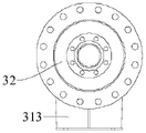
As shown in fig. 7-8, the heat sink of this embodiment includes a heat dissipating oil pipe assembly and a cylinder 31, two ends of the cylinder 31 are respectively connected to an oil inlet end cover 32 and an oil outlet end cover 33 by flanges, the oil inlet end cover 32 and the oil outlet end cover 33 are communicated by a plurality of cooling oil pipes 11 connected in parallel, the plurality of cooling oil pipes 11 are located in the cylinder 31, and a water inlet 311 and a water outlet 312 are opened on an upper wall of the cylinder 31. When in use, cooling oil enters from the oil inlet end cover 32 and flows out from the oil outlet end cover 33 through a plurality of cooling oil pipes 11 connected in parallel; cooling water enters from the water inlet 311 and then flows out from the water outlet 312; in the process, a plurality of cooling oil pipes 11 connected in parallel are cooled by cooling water, so that heat exchange is realized. In the same way, the radiator adopts the radiating oil pipe component, so the radiating effect is good, and the radiating requirement can be met.
Preferably, the lower wall of the cylinder 31 is provided with support legs 313. The supporting legs 313 can support the cylindrical body 31 from the ground, thereby reducing corrosion damage to the cylindrical body 31.
The above description is only an embodiment of the present invention, and not intended to limit the scope of the present invention, and all modifications of equivalent structures and equivalent processes, which are made by using the contents of the present specification and the accompanying drawings, or directly or indirectly applied to other related technical fields, are included in the scope of the present invention.
Claims (10)
1. The heat dissipation oil pipe assembly is characterized by comprising a cooling oil pipe (11), wherein a pin fin pipe (12) is arranged inside the cooling oil pipe (11), the pin fin pipe (12) comprises a pipe body (121), pin fins (122) are arranged in the circumferential direction and the axial direction of the outer wall of the pipe body (121), and two ends of the pipe body (121) are plugged.
2. The heat sink tubing assembly of claim 1, wherein: the pin fin (122) abuts against the inner wall of the cooling oil pipe (11).
3. The heat sink tubing assembly of claim 1, wherein: the pin fins (122) are obliquely arranged towards the oil outlet direction along the oil inlet direction of the cooling oil pipe (11).
4. The heat sink tubing assembly of claim 1, wherein: the pin fins (122) are uniformly arranged along the circumferential direction of the tube body (121).
5. The heat sink tubing assembly of claim 1, wherein: the pin fins (122) are uniformly arranged along the axial direction of the tube body (121).
6. The heat sink tubing assembly of claim 1, wherein: and bolts (123) are connected to the two ends of the pipe body (121) in a threaded manner.
7. A heat sink, comprising: the heat sink oil pipe assembly, the oil inlet pipe (21), the oil outlet pipe (22), and the air-cooled heat sink fins (23) as set forth in any one of claims 1 to 6; the oil inlet pipe (21) is communicated with the oil outlet pipe (22) through a plurality of cooling oil pipes (11) which are connected in parallel, and the air-cooled radiating fins (23) are arranged outside the plurality of cooling oil pipes (11) which are connected in parallel.
8. The heat sink of claim 7, wherein: the radiator also comprises two fans (24) for air-cooling the radiating fins (23).
9. A heat sink, comprising: the radiator oil tube assembly according to any one of claims 1 to 6, and a barrel (31); the both ends of barrel (31) flange joint respectively have oil feed end cover (32) and end cover (33) of producing oil, through many parallelly connected cooling oil pipe (11) intercommunication between oil feed end cover (32) and the end cover (33) of producing oil, and many cooling oil pipe (11) are located in barrel (31), water inlet (311) and delivery port (312) have been seted up to the upper wall of barrel (31).
10. The heat sink of claim 9, wherein: the lower wall of the cylinder (31) is provided with supporting legs (313).
Priority Applications (1)
| Application Number | Priority Date | Filing Date | Title |
|---|---|---|---|
| CN202122147389.0U CN216592894U (en) | 2021-09-06 | 2021-09-06 | Heat dissipation oil pipe assembly and radiator |
Applications Claiming Priority (1)
| Application Number | Priority Date | Filing Date | Title |
|---|---|---|---|
| CN202122147389.0U CN216592894U (en) | 2021-09-06 | 2021-09-06 | Heat dissipation oil pipe assembly and radiator |
Publications (1)
| Publication Number | Publication Date |
|---|---|
| CN216592894U true CN216592894U (en) | 2022-05-24 |
Family
ID=81636233
Family Applications (1)
| Application Number | Title | Priority Date | Filing Date |
|---|---|---|---|
| CN202122147389.0U Active CN216592894U (en) | 2021-09-06 | 2021-09-06 | Heat dissipation oil pipe assembly and radiator |
Country Status (1)
| Country | Link |
|---|---|
| CN (1) | CN216592894U (en) |
-
2021
- 2021-09-06 CN CN202122147389.0U patent/CN216592894U/en active Active
Similar Documents
| Publication | Publication Date | Title |
|---|---|---|
| CN216592894U (en) | Heat dissipation oil pipe assembly and radiator | |
| CN107357397A (en) | A kind of novel C PU radiators | |
| CN207261103U (en) | Energy-efficient automobile radiator | |
| CN206194729U (en) | Novel water cooling heat radiator | |
| CN105261449A (en) | Oil-cooled transformer with bundle-type radiator | |
| CN207993624U (en) | A kind of almag cooler | |
| CN210660854U (en) | Hydraulic oil circulation heat sink | |
| CN207379347U (en) | A kind of detachable finned air-cooled heat exchanger tube | |
| WO2018161615A1 (en) | Finned radiator with helical twisted stripe | |
| CN206056372U (en) | A kind of radiating tube for strengthening radiating effect | |
| CN206093474U (en) | Oil cooling device | |
| CN212518302U (en) | Heat dissipation type bus duct | |
| CN109026326A (en) | A kind of automotive engine radiator | |
| CN213396660U (en) | Explosion-proof water-cooled heat pipe exchanger device | |
| CN211289165U (en) | Natural gas pipeline cooling device | |
| CN210004806U (en) | cage type radiator | |
| CN203879608U (en) | Water-cooled radiator | |
| CN207801637U (en) | Motor radiating shell and electromotor cooling system | |
| CN209642494U (en) | Motor and heat exchanger integrated radiating structure | |
| CN211823940U (en) | Condenser | |
| CN218480943U (en) | Heat radiator | |
| CN217327950U (en) | Hydraulic oil heat dissipation device of brick making machine | |
| CN212898810U (en) | Casing structure of wind driven generator | |
| TWM549432U (en) | Heat dissipating fin structure of radiator | |
| CN213928539U (en) | Radiator of diesel engine |
Legal Events
| Date | Code | Title | Description |
|---|---|---|---|
| GR01 | Patent grant | ||
| GR01 | Patent grant |