CN216584356U - Water pollution administers and uses circulation clarification plant - Google Patents
Water pollution administers and uses circulation clarification plant Download PDFInfo
- Publication number
- CN216584356U CN216584356U CN202220139688.1U CN202220139688U CN216584356U CN 216584356 U CN216584356 U CN 216584356U CN 202220139688 U CN202220139688 U CN 202220139688U CN 216584356 U CN216584356 U CN 216584356U
- Authority
- CN
- China
- Prior art keywords
- clarification plant
- purification equipment
- plant body
- threaded rod
- water pollution
- Prior art date
- Legal status (The legal status is an assumption and is not a legal conclusion. Google has not performed a legal analysis and makes no representation as to the accuracy of the status listed.)
- Active
Links
Images


Classifications
-
- Y—GENERAL TAGGING OF NEW TECHNOLOGICAL DEVELOPMENTS; GENERAL TAGGING OF CROSS-SECTIONAL TECHNOLOGIES SPANNING OVER SEVERAL SECTIONS OF THE IPC; TECHNICAL SUBJECTS COVERED BY FORMER USPC CROSS-REFERENCE ART COLLECTIONS [XRACs] AND DIGESTS
- Y02—TECHNOLOGIES OR APPLICATIONS FOR MITIGATION OR ADAPTATION AGAINST CLIMATE CHANGE
- Y02W—CLIMATE CHANGE MITIGATION TECHNOLOGIES RELATED TO WASTEWATER TREATMENT OR WASTE MANAGEMENT
- Y02W10/00—Technologies for wastewater treatment
- Y02W10/10—Biological treatment of water, waste water, or sewage
Abstract
The utility model provides a water pollution administers and uses circulation clarification plant, relates to sewage treatment technical field, including the clarification plant body, vertical height adjusting mechanism is installed at clarification plant body top, the multiunit install between the vertical height adjusting mechanism and scrape the sediment ware, clarification plant body bottom is equipped with scrapes mud mechanism, the sludge impoundment has been seted up to the bottom of clarification plant body inner chamber, and the fixed intercommunication in front of clarification plant body has the mud pipe. The utility model discloses a set up movable block, flexible spring, first threaded rod and scrape the sediment ware, can highly adjusting of scraping the sediment ware. Through setting up stock, scraper blade, brake motor and second threaded rod, made things convenient for operating personnel to clear up the inside mud of clarification plant body.
Description
Technical Field
The utility model relates to a sewage treatment technical field specifically is a water pollution administers and uses circulation clarification plant.
Background
The sewage treatment is a process for purifying sewage to meet the requirement of discharging the sewage into a certain water body or reusing the sewage, is widely applied to various fields of building, agriculture, transportation, energy, petrochemical, environment-friendly urban landscape medical catering and the like, and is also increasingly used in daily life of common people.
At present, the enterprise is when administering sewage, often need use clarification plant to purify sewage, and current clarification plant is at the in-process of in-service use, though can realize basic purification's purpose to sewage, but it often need use to scrape the sediment ware and strike off the impurity on sewage surface, and the sediment ware that scrapes that has now adopts fixed structure to can't adjust its height according to the water level, and then reduced its efficiency of purifying sewage. Meanwhile, when purifying sewage, the existing purifying equipment often needs to precipitate sludge in the sewage, and the existing purifying device does not have a good structure for cleaning the sludge in the device, so that a large amount of clear water needs to be discharged together when the sludge needs to be cleaned, the clear water and the sludge are mixed, and then the clear water and the sludge need to be secondarily purified, the labor intensity of operators is improved, and the improvement is needed.
Disclosure of Invention
To the problem of mentioning among the prior art, the utility model provides a water pollution administers and uses circulation clarification plant can avoid the emergence of above-mentioned problem.
The utility model provides a technical scheme that its technical problem adopted is:
the utility model provides a water pollution administers with circulation clarification plant, includes the clarification plant body, vertical height adjusting mechanism is installed at clarification plant body top, the multiunit install between the vertical height adjusting mechanism and scrape the sediment ware, clarification plant body bottom is equipped with scrapes mud mechanism, the sludge impoundment has been seted up to the bottom of clarification plant body inner chamber, and the fixed intercommunication in front of clarification plant body has the mud pipe.
Further, vertical height control mechanism includes the dead lever, the surface sliding fit of dead lever has the movable block, and the right side fixed mounting of movable block has the fly leaf, and fly leaf fixedly connected with scrapes the sediment ware, be equipped with flexible spring between movable block and the clarification plant body, the top fixed mounting of dead lever has the rectangular block, and the internal thread of rectangular block has cup jointed first threaded rod, and the top fixed mounting of first threaded rod has the piece soon, the lower tip of first threaded rod supports and leans on the fly leaf.
Further, flexible spring has been cup jointed on the dead lever, flexible spring one end is connected with the movable block, and the other end is connected with the clarification plant body.
Further, the inside waste slag pond that is equipped with of clarification plant body, the fixed intercommunication in bottom in waste slag pond has the scum pipe, the waste slag pond cooperatees with the scum ware.
Further, the front of clarification plant body is equipped with the inlet tube, and the fixed intercommunication in top of clarification plant body has the hopper, and the inside of clarification plant body is equipped with rabbling mechanism, and the fixed intercommunication in front of clarification plant body has dissolved air pump, and the upper right corner of clarification plant body inner chamber is equipped with the clean water basin, and the left side in clean water basin is equipped with the waste residue pond.
Furthermore, a coagulant and a flocculant are respectively added into the two hoppers.
Further, it includes the motor to scrape mud mechanism, the motor is fixed in the clarification plant body outside, motor output shaft has the second threaded rod, threaded connection has the scraper blade on the second threaded rod, the scraper blade tip is equipped with the through-hole, the stock has been cup jointed in the through-hole, the both ends fixed connection of stock is inside the clarification plant body.
Furthermore, a water valve is arranged at the top of the sludge discharge pipe.
Further, the inside fixed mounting of clarification plant body has the installation piece, and two installation pieces are in the scraper blade both sides respectively, the shape of installation piece is triangle-shaped.
The utility model has the advantages that: the utility model discloses a set up movable block, flexible spring, first threaded rod and scrape the sediment ware, can highly adjusting of scraping the sediment ware. Through setting up stock, scraper blade, brake motor and second threaded rod, can strike off the mud of clarification plant body inner chamber bottom and promote the inside in sludge impoundment, open the water valve convenience of mud pipe afterwards and unify the discharge with mud, and then made things convenient for operating personnel to clear up the inside mud of clarification plant body.
Drawings
Figure 1 is a schematic three-dimensional structure of the present invention,
figure 2 is a front cross-sectional view of the present invention,
figure 3 is a top cross-sectional view of the present invention,
figure 4 is a schematic three-dimensional structure diagram of a second angle of the present invention,
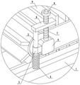
figure 5 is an enlarged view of a portion of figure 1 at a,
in the figure: 1 clarification plant body, 2 dead levers, 3 movable blocks, 4 fly leaves, 5 flexible spring, 6 rectangular blocks, 7 first threaded rods, 8 piece soon, 9 scum scrapers, 10 inlet tubes, 11 hoppers, 12 rabbling mechanisms, 13 dissolved air pump, 14 clean water basin, 15 waste residue ponds, 16 communicating pipes, 17 drain pipes, 18 scum pipes, 19 installation pieces, 20 stock, 21 scraper blades, 22 motors, 23 second threaded rods, 24 sludge impoundments, 25 sludge pipes.
Detailed Description
The technical solutions in the embodiments of the present invention will be described clearly and completely with reference to the accompanying drawings in the embodiments of the present invention, and it is obvious that the described embodiments are only some embodiments of the present invention, not all embodiments. Based on the embodiments in the present invention, all other embodiments obtained by a person skilled in the art without creative work belong to the protection scope of the present invention.
As shown in fig. 1 to 5, a water pollution administers and uses circulation clarification plant, includes clarification plant body 1, clarification plant body installs vertical height adjustment mechanism in the top, the multiunit vertical height adjustment mechanism installs the sediment ware 9 of scraping between the mechanism, and wherein the sediment ware of scraping is prior art, can purchase outward. The clarification plant body bottom is equipped with scrapes mud mechanism, sludge tank 24 has been seted up to the bottom of clarification plant body 1 inner chamber, and clarification plant body 1's front fixed intercommunication has mud pipe 25.
In at least one embodiment, vertical height control mechanism includes dead lever 2, the surface sliding fit of dead lever 2 has movable block 3, and the right side fixed mounting of movable block 3 has fly leaf 4, and fly leaf fixedly connected with scrapes the sediment ware, be equipped with flexible spring 5 between movable block and the clarification plant body, the top fixed mounting of dead lever 2 has rectangular block 6, and the internal thread of rectangular block 6 has cup jointed first threaded rod 7, and the top fixed mounting of first threaded rod 7 has revolves piece 8, the lower tip of first threaded rod supports and leans on the fly leaf. Because the design of flexible spring 5 for the movable block 3 has good elasticity reset performance, flexible spring 5 is compression state this moment, consequently can apply an elasticity to movable block 3, thereby can play the supporting effect to movable block 3, simultaneously because the rotation of first threaded rod 7, through the cooperation of first threaded rod 7 with fly leaf 4, make first threaded rod 7 will extrude fly leaf 4, and then can adjust the position of fly leaf 4, made things convenient for operating personnel to adjust the height of scraping sediment ware 9.
The scheme refines, flexible spring has been cup jointed on the dead lever, flexible spring one end is connected with the movable block, and the other end is connected with the clarification plant body.
In at least one embodiment, a waste slag pool 15 is arranged inside the purifying equipment body, a slag discharge pipe 18 is fixedly communicated with the bottom of the waste slag pool 15, and the waste slag pool 15 is matched with a slag scraper.
In at least one embodiment, the front of clarification plant body 1 is equipped with inlet tube 10, and the fixed intercommunication in top of clarification plant body 1 has hopper 11, and the inside of clarification plant body 1 is equipped with rabbling mechanism 12, and the fixed intercommunication in front of clarification plant body 1 has dissolved air pump 13, and the upper right corner of clarification plant body 1 inner chamber is equipped with clean water basin 14, and the left side of clean water basin 14 is equipped with waste residue pond 15. Because the design of clean water basin 14 makes the clear water at clarification plant body 1 inner chamber middle part will flow in the inside of clean water basin 14 through the principle of linker, and rivers will be followed drain pipe 17 and discharged, simultaneously because the design of waste residue pond 15 for scrape off the waste residue on clarification plant body 1 inner chamber water surface and drop to waste residue pond 15 and discharge from slag discharge pipe 18 through scraping sediment ware 9.
The scheme is refined, and two 11 in the hopper can add coagulant and flocculating agent respectively, because the design of hopper 11, through to its inside coagulant and flocculating agent that adds, make it stir it through rabbling mechanism 12, through mixing with sewage for can separate impurity in the sewage and clear water, and then reach the effect of purifying sewage.
In at least one embodiment, the mud scraping mechanism comprises a motor 22, the motor is fixed on the outer side of the purifying equipment body, the output shaft of the motor is connected with a second threaded rod 23, a scraper 21 is connected to the second threaded rod in a threaded mode, a through hole is formed in the end portion of the scraper, a long rod 20 is sleeved in the through hole, two ends of the long rod are fixedly connected inside the purifying equipment body, and a water valve is arranged at the top of the mud discharging pipe 25. Because the design of second threaded rod 23 will make second threaded rod 23 take place to rotate when motor 22 operation to make second threaded rod 23 drive scraper blade 21 and remove along the surface of stock 20, make it strike off the mud of clarification plant body 1 inner chamber bottom and promote the inside of sludge impoundment 24, open the water valve of mud pipe 25 afterwards and conveniently discharge mud in unison.
Further, the inside fixed mounting of clarification plant body 1 has installation piece 19, and two installation pieces are in the scraper blade both sides respectively, the shape of installation piece 19 is triangle-shaped, because the design of installation piece 19 for mud that deposits in the sewage will be followed the inclined plane of installation piece 19 and slided downwards, thereby conveniently strike off in unison.
In the working mode, firstly, an operator can rotate the rotary block 8 to enable the rotary block 8 to drive the first threaded rod 7 to rotate, at the moment, due to the rotation of the first threaded rod 7, through the matching between the first threaded rod 7 and the rectangular block 6, the first threaded rod 7 can move downwards along the inner surface of the rectangular block 6, so that the movable plate 4 can be extruded to drive the movable plate 4 to move downwards, meanwhile, due to the matching between the fixed rod 2 and the movable block 3, the movable block 3 can move upwards and downwards along the outer surface part of the fixed rod 2, at the moment, because the flexible spring 5 is in a compressed state, an elastic force can be applied to the movable block 3, so that the movable block 3 can be driven to move upwards, further, the height of the slag scraper 9 can be adjusted, when the operator needs to clean sludge in the purifying equipment body 1, at the moment, the operator can start the motor 22, because motor 22's operation will make second threaded rod 23 take place to rotate, because the cooperation between second threaded rod 23 and the scraper blade 21 this moment, will make second threaded rod 23 will drive scraper blade 21 and remove along the surface of stock 20, make can strike off the mud of clarification plant body 1 inner chamber bottom and promote the inside of sludge impoundment 24, operating personnel opens the water valve of mud pipe 25 afterwards and conveniently unifies the discharge with mud, operating personnel can close the water valve when mud is cleared.
In addition to the technical features described in the specification, the technology is known to those skilled in the art.
Claims (8)
1. The utility model provides a water pollution administers and uses circulation clarification plant, its characterized in that, includes the clarification plant body, vertical altitude mixture control mechanism is installed at clarification plant body top, the multiunit install between the vertical altitude mixture control mechanism and scrape the sediment ware, clarification plant body bottom is equipped with scrapes mud mechanism, the sludge impoundment has been seted up to the bottom of clarification plant body inner chamber, and the fixed intercommunication in front of clarification plant body has the mud pipe.
2. The circulating purification equipment for water pollution treatment according to claim 1, wherein the vertical height adjusting mechanism comprises a fixed rod, a movable block is slidably fitted on the outer surface of the fixed rod, a movable plate is fixedly mounted on the right side of the movable block, a slag scraper is fixedly connected with the movable plate, a flexible spring is arranged between the movable block and the purification equipment body, a rectangular block is fixedly mounted at the top of the fixed rod, a first threaded rod is sleeved on the internal thread of the rectangular block, a rotary block is fixedly mounted at the top of the first threaded rod, and the lower end of the first threaded rod abuts against the movable plate.
3. The circulating purification equipment for water pollution treatment according to claim 2, wherein a flexible spring is sleeved on the fixed rod, one end of the flexible spring is connected with the movable block, and the other end of the flexible spring is connected with the purification equipment body.
4. The circulating purification apparatus for water pollution treatment according to any one of claims 1 to 3, wherein the mud scraping mechanism comprises a motor, the motor is fixed outside the purification apparatus body, the output shaft of the motor is connected with a second threaded rod, a scraping plate is connected to the second threaded rod through a thread, the end of the scraping plate is provided with a through hole, a long rod is sleeved in the through hole, and two ends of the long rod are fixedly connected inside the purification apparatus body.
5. The recycling purification apparatus for water pollution control according to claim 4, wherein a water valve is provided on the top of said sludge discharging pipe.
6. The circulating purification equipment for water pollution treatment according to claim 4, wherein the inside of the purification equipment body is fixedly provided with mounting blocks, the two mounting blocks are respectively arranged at two sides of the scraper, and the mounting blocks are triangular.
7. The circulating purification equipment for water pollution treatment according to claim 1, wherein a waste slag pool is arranged inside the purification equipment body, a slag discharge pipe is fixedly communicated with the bottom of the waste slag pool, and the waste slag pool is matched with the slag scraper.
8. The circulating purification equipment for water pollution treatment according to claim 1 or 7, wherein a water inlet pipe is arranged on the front side of the purification equipment body, a hopper is fixedly communicated with the top of the purification equipment body, a stirring mechanism is arranged inside the purification equipment body, a dissolved air pump is fixedly communicated with the front side of the purification equipment body, a clean water tank is arranged at the upper right corner of the inner cavity of the purification equipment body, and a waste residue tank is arranged at the left side of the clean water tank.
Priority Applications (1)
| Application Number | Priority Date | Filing Date | Title |
|---|---|---|---|
| CN202220139688.1U CN216584356U (en) | 2022-01-19 | 2022-01-19 | Water pollution administers and uses circulation clarification plant |
Applications Claiming Priority (1)
| Application Number | Priority Date | Filing Date | Title |
|---|---|---|---|
| CN202220139688.1U CN216584356U (en) | 2022-01-19 | 2022-01-19 | Water pollution administers and uses circulation clarification plant |
Publications (1)
| Publication Number | Publication Date |
|---|---|
| CN216584356U true CN216584356U (en) | 2022-05-24 |
Family
ID=81634857
Family Applications (1)
| Application Number | Title | Priority Date | Filing Date |
|---|---|---|---|
| CN202220139688.1U Active CN216584356U (en) | 2022-01-19 | 2022-01-19 | Water pollution administers and uses circulation clarification plant |
Country Status (1)
| Country | Link |
|---|---|
| CN (1) | CN216584356U (en) |
-
2022
- 2022-01-19 CN CN202220139688.1U patent/CN216584356U/en active Active
Similar Documents
| Publication | Publication Date | Title |
|---|---|---|
| CN111001205A (en) | Sewage collection and treatment impurity self-cleaning device and using method thereof | |
| CN112777802A (en) | Environment-friendly domestic sewage treatment precipitation device | |
| CN215995731U (en) | Sludge discharging device and sewage treatment system for water treatment plant | |
| CN216584356U (en) | Water pollution administers and uses circulation clarification plant | |
| CN214218338U (en) | Sewage treatment equipment for performing secondary treatment on residue remained on filter plate | |
| CN212166649U (en) | Sewage collection handles impurity self-cleaning device | |
| CN104499562A (en) | Environment-friendly excrement carbonization toilet | |
| CN206767850U (en) | A kind of sewage treatment unit | |
| CN204326233U (en) | Ight soil carbonization environment protection water closet | |
| CN220056409U (en) | Sewage treatment water tank | |
| CN111517501A (en) | Sewage treatment device convenient to overhaul | |
| CN207792936U (en) | A kind of sewage-treatment plant | |
| CN207091084U (en) | Chemical oil remover | |
| CN219502038U (en) | Central transmission mud scraper for sewage treatment | |
| CN220201694U (en) | Water circulation treatment device for landscape design | |
| CN220351831U (en) | Breed effluent treatment plant | |
| CN217015536U (en) | Back flushing device for sewage treatment pipeline | |
| CN214399963U (en) | Integrated SBR reactor for wastewater treatment | |
| CN219363451U (en) | Sewage treatment biological filter | |
| CN220723890U (en) | Coagulation device for water pollution chemical treatment | |
| CN220812096U (en) | Water resource sewage treatment device | |
| CN220376506U (en) | Urban water body garbage purification device | |
| CN220223893U (en) | Mixing station waste water precipitation device | |
| CN220919010U (en) | Tank structure of environment-friendly waste mud stirring tank | |
| CN220867169U (en) | Integrated water purification treatment device |
Legal Events
| Date | Code | Title | Description |
|---|---|---|---|
| GR01 | Patent grant | ||
| GR01 | Patent grant |