CN216576597U - High-speed horizontal machining center machine tool - Google Patents
High-speed horizontal machining center machine tool Download PDFInfo
- Publication number
- CN216576597U CN216576597U CN202122279104.9U CN202122279104U CN216576597U CN 216576597 U CN216576597 U CN 216576597U CN 202122279104 U CN202122279104 U CN 202122279104U CN 216576597 U CN216576597 U CN 216576597U
- Authority
- CN
- China
- Prior art keywords
- plate
- supporting
- threaded rod
- machining center
- horizontal machining
- Prior art date
- Legal status (The legal status is an assumption and is not a legal conclusion. Google has not performed a legal analysis and makes no representation as to the accuracy of the status listed.)
- Active
Links
Images


Landscapes
- Jigs For Machine Tools (AREA)
Abstract
The utility model discloses a high-speed horizontal machining center machine tool, and relates to the technical field of machine tools. The utility model comprises a base plate, wherein four supporting mechanisms are arranged on the lower side of the base plate, a first fixing plate is arranged on each of one sides of the four supporting mechanisms, a first threaded rod is rotatably matched in the first fixing plate, a first clamping plate is rotatably matched at one end of the first threaded rod, a second fixing plate is slidably matched on the upper side of the base plate, and a plurality of supporting seats are arranged on the upper side of the second fixing plate and two second clamping plates are slidably matched. The base plate is conveniently supported under the action of the supporting mechanism, the base plate is conveniently fixed on the upper side of the milling machine under the action of rotation of the first threaded rod through the first fixing plate and the first clamping plate, workpieces are conveniently lifted and moved under the action of the second fixing plate and the L-shaped supporting plate, and the workpieces placed on the upper side of the supporting seat are conveniently clamped and fixed under the action of the supporting seat and the action of the baffle on one side of the second clamping plate.
Description
Technical Field
The utility model belongs to the technical field of machine tools, and particularly relates to a high-speed horizontal machining center machine tool.
Background
With the increasingly wide application of permanent magnet servo motors in the manufacturing industry of key equipment such as injection molding machines and the like, the market puts higher and higher requirements on the easy maintainability, the low noise performance and the precision transmission performance of the permanent magnet servo motors, the innovation of the transmission shaft structure of the permanent magnet servo motors is more the goal and the important means of the development profit of motor enterprises, and meanwhile, the use of motor workpieces can increase the use effect and the service life of the transmission shaft.
In the prior art, a milling machine is generally adopted for bore cutting processing during processing of a motor workpiece, but the existing milling machine is inconvenient to move the workpiece in the using process, so that the bore milling process is slow and the bore milling effect is poor.
SUMMERY OF THE UTILITY MODEL
The utility model aims to provide a high-speed horizontal machining center machine tool, which solves the technical problems of slow bore milling and poor bore milling effect caused by inconvenient movement of a workpiece.
In order to solve the technical problems, the utility model is realized by the following technical scheme:
the utility model provides a high-speed horizontal machining center lathe, which comprises a substrate, the downside of base plate is equipped with four supporting mechanism, one side of four supporting mechanism all is equipped with first fixed plate, the inside normal running fit of first fixed plate has first threaded rod, the one end normal running fit of first threaded rod has first splint, the upside sliding fit of base plate has the second fixed plate, a plurality of supporting seats have been installed to the upside of second fixed plate, sliding fit has two second splint, one side of two second splint all is equipped with the baffle, downside normal running fit second threaded rod, second threaded rod normal running fit has L shape layer board.
Optionally, the supporting mechanism is including installing the first support post in base plate one side, and first supporting shoe has been installed to the downside of first support post, and two electric putter have been installed to the downside of first supporting shoe, and the equal clearance fit of one end of two electric putter has the base, and the one end of first support post is equipped with first fixed block, and one side normal running fit of first fixed block has the second fixed column, and first fixed plate clearance fit is at the downside of second fixed column.
Optionally, four hydraulic push rods are slidably fitted between the base plate and the second fixing plate.
Optionally, the upper side of the second fixing plate is slidably fitted with two second supporting columns, the upper ends of the two second supporting columns are provided with second clamping plates, and the two second supporting columns are located on one side of the plurality of first fixing columns.
Optionally, a buffer is arranged between the second clamping plate and the baffle plate.
Optionally, the lower side of the second clamping plate is provided with a first supporting plate, the second threaded rod is rotatably matched inside the first supporting plate, one end of the second threaded rod is provided with a second bearing, and the L-shaped supporting plate is arranged on one side of the second bearing.
Optionally, four supporting rods are installed on the upper side of the second fixing plate, the rotating wheels are matched with the upper sides of the four supporting rods in a rotating mode, and the L-shaped supporting plate is matched with the upper sides of the rotating wheels in a sliding mode.
The embodiment of the utility model has the following beneficial effects:
according to the embodiment of the utility model, the substrate is conveniently supported under the action of the supporting mechanism, the substrate is conveniently fixed on the upper side of the milling machine under the action of rotation of the first threaded rod through the first fixing plate and the first clamping plate, the workpiece is conveniently lifted and moved under the action of the second fixing plate and the L-shaped supporting plate, the workpiece placed on the upper side of the supporting seat is conveniently clamped and fixed under the action of the supporting seat and the baffle plate on one side of the second clamping plate, the force of the baffle plate is conveniently buffered under the action of the buffer, the damage to the side edge of the workpiece is reduced, and the moving and processing of the workpiece are facilitated through the process.
Of course, it is not necessary for any product in which the utility model is practiced to achieve all of the above-described advantages at the same time.
Drawings
In order to more clearly illustrate the technical solutions of the embodiments of the present invention, the drawings used in the description of the embodiments will be briefly introduced below, and it is obvious that the drawings in the following description are only some embodiments of the present invention, and it is obvious for those skilled in the art that other drawings can be obtained according to the drawings without creative efforts.
FIG. 1 is a schematic perspective view of an embodiment of the present invention;
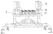
FIG. 2 is a schematic cross-sectional view of an embodiment of the present invention;
FIG. 3 is a schematic view of the structure at B in FIG. 2;
FIG. 4 is a schematic view of the structure at A in FIG. 2;
FIG. 5 is a schematic top view of a three-dimensional structure according to an embodiment of the present invention;
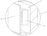
fig. 6 is a schematic structural diagram at C in fig. 5.
Wherein the figures include the following reference numerals:
the base plate 1, first spout 2, first slider 3, hydraulic rod 4, second fixed plate 5, second spout 6, second slider 7, second support column 8, second splint 9, buffer 10, baffle 11, first backup pad 12, second threaded rod 13, second bearing 14, L shape layer board 15, bracing piece 16, first fixed column 17, first universal ware 18, first support column 24, first supporting block 25, electric putter 26, second universal ware 27, base 28, first fixed block 29, second fixed column 30, third universal ware 31, first fixed plate 32, first threaded rod 33, first splint 34, supporting seat 35.
Detailed Description
The technical solutions in the embodiments of the present invention will be clearly and completely described below with reference to the drawings in the embodiments of the present invention, and it is obvious that the described embodiments are only a part of the embodiments of the present invention, and not all of the embodiments. The following description of at least one exemplary embodiment is merely illustrative in nature and is in no way intended to limit the utility model, its application, or uses.
To maintain the following description of the embodiments of the present invention clear and concise, a detailed description of known functions and known components of the utility model have been omitted.
Referring to fig. 1-6, in the present embodiment, a high-speed horizontal machining center machine tool is provided, which includes a base plate 1, four supporting mechanisms are disposed on a lower side of the base plate 1, a first fixing plate 32 is disposed on each of four supporting mechanisms, a first threaded rod 33 is rotatably engaged inside the first fixing plate 32, a first clamping plate 34 is rotatably engaged at one end of the first threaded rod 33, specifically, a first bearing is disposed at one end of the first threaded rod 33, the first clamping plate 34 is disposed at one side of the first bearing, a second fixing plate 5 is slidably engaged on an upper side of the base plate 1, a plurality of supporting seats 35 are disposed on an upper side of the second fixing plate 5, specifically, a first fixing column 17 is disposed between the second fixing plate 5 and the supporting seats 35, a first gimbal 18 is disposed at an upper end of the first fixing column 17, and two second clamping plates 9 are slidably engaged on upper sides of the plurality of the first gimbal 18, one side of each of the two second clamping plates 9 is provided with a baffle 11 and a second threaded rod 13 with the lower side in running fit, and the second threaded rod 13 is in running fit with an L-shaped supporting plate 15.
The application of one aspect of the embodiment is as follows: in the process that the device used, put first fixed plate 32 and first splint 34 card on the milling machine both sides through rotating first threaded rod 33 earlier, then place the upside of second fixed plate 5 with the work piece, supporting seat 35 can hold in the palm the putting to the work piece, then two second splint 9 that slide make baffle 11 can carry out the centre gripping to the both sides of work piece, the in-process buffer 10 of centre gripping can cushion the both sides of work piece, rotate second threaded rod 13 afterwards and make L shape layer board 15 can press from both sides the downside of work piece tightly, and then accomplish the fixed to the work piece, slide second fixed plate 5 at last and adjust the distance between work piece and the milling cutter. It should be noted that all the electric devices referred to in this application may be powered by a storage battery or an external power source.
Through the effect at supporting mechanism, the convenience is supported base plate 1, under first threaded rod 33 pivoted effect through first fixed plate 32 and first splint 34, the upside at the milling machine is fixed with base plate 1 to the convenience, effect through second fixed plate 5 and L shape layer board 15, the convenience is lifted the work piece and is removed, effect through supporting seat 35, effect through second splint 9 side shield 11, it is fixed to conveniently carry out the centre gripping to the work piece of placing supporting seat 35 upside, the effect through buffer 10 is convenient to cushion the power of baffle 11, reduce the injury that the work piece side received, the removal and the processing to the work piece have been made things convenient for through above-mentioned process.
Referring to fig. 6, the supporting mechanism of the present embodiment includes a first supporting column 24 installed on one side of the substrate 1, a first supporting block 25 installed on a lower side of the first supporting column 24, two electric push rods 26 installed on a lower side of the first supporting block 25, a base 28 movably fitted on one end of each of the two electric push rods 26, specifically, a second universal coupler 27 installed on a lower side of each of the two electric push rods 26, a base 28 installed on one side of the second universal coupler 27, a first fixing block 29 installed on one end of the first supporting column 24, a second fixing column 30 rotatably fitted on one side of the first fixing block 29, a first fixing plate 32 movably fitted on a lower side of the second fixing column 30, specifically, a third universal coupler 31 installed on a lower side of the second fixing column 30, a first fixing plate 32 installed on a lower side of the third universal coupler 31, and a corresponding relationship between the first fixing plate 32 and the milling machine edge can be conveniently adjusted through an effect of the third universal coupler 31, the distance between first splint 34 and the first threaded rod 33 is conveniently adjusted through the effect of first threaded rod 33, and then conveniently fixes first fixed plate 32 and first splint 34 on the edge of milling machine, and then accomplishes the fixed to base plate 1.
Referring to fig. 1, four hydraulic push rods 4 are slidably engaged between the substrate 1 and the second fixing plate 5 in the embodiment, specifically, two first sliding grooves 2 are formed in the upper side of the substrate 1, two first sliding blocks 3 are slidably engaged inside the two first sliding grooves 2, the four hydraulic push rods 4 are mounted on the upper sides of the four first sliding blocks 3, and a workpiece placed on the upper side of the second fixing plate 5 can be conveniently moved by the action of the four hydraulic push rods 4 slidably engaged on the upper side of the substrate 1.
Referring to fig. 3, a buffer 10 is disposed between the second clamping plate 9 and the baffle 11, so that the buffer 10 can buffer the side wall of the workpiece during clamping the two sides of the workpiece, thereby reducing damage to the side wall of the workpiece
Please refer to fig. 1, in the embodiment, two second supporting columns 8 are slidably engaged on the upper side of the second fixing plate 5, a second clamping plate 9 is installed at the upper ends of the two second supporting columns 8, specifically, four second sliding chutes 6 are installed on the upper side of the second fixing plate 5, second sliding blocks 7 are respectively slidably engaged inside the four second sliding chutes 6, the two second supporting columns 8 are installed on the upper sides of the two adjacent second sliding blocks 7, the two second supporting columns 8 are located on one side of a plurality of first fixing columns 17, and the distance from the second clamping plate 9 to the side surface of the workpiece is conveniently adjusted by the sliding engagement of the two second supporting columns 8 on the upper side of the second fixing plate 5, so as to conveniently limit the workpiece.
Please refer to fig. 4, a first supporting plate 12 is disposed on a lower side of the second clamping plate 9 of the present embodiment, the second threaded rod 13 is rotatably fitted inside the first supporting plate 12, a second bearing 14 is disposed at one end of the second threaded rod 13, four supporting rods 16 are disposed on an upper side of the second fixing plate 5, a rotating wheel is rotatably fitted on upper sides of the four supporting rods 16, the L-shaped supporting plate 15 is slidably fitted on an upper side of the rotating wheel through the second threaded rod 13, so as to conveniently adjust a position of the L-shaped supporting plate 15, further, the L-shaped supporting plate 15 is convenient to lift a bottom side of a workpiece, and simultaneously, an inclination angle of the workpiece is convenient to adjust, and the L-shaped supporting plate 15 is convenient to slide above the supporting rod 16 through the rotating wheel rotatably fitted on the upper side of the supporting rod 16.
The above embodiments may be combined with each other.
It should be noted that in the description of the present specification, descriptions such as "first", "second", etc. are only used for distinguishing features, and do not have an actual order or meaning, and the present application is not limited thereto.
In the description herein, references to the description of "one embodiment," "an example," "a specific example" or the like are intended to mean that a particular feature, structure, material, or characteristic described in connection with the embodiment or example is included in at least one embodiment or example of the utility model. In this specification, the schematic representations of the terms used above do not necessarily refer to the same embodiment or example. Furthermore, the particular features, structures, materials, or characteristics described may be combined in any suitable manner in any one or more embodiments or examples.
The preferred embodiments of the utility model disclosed above are intended to be illustrative only. The preferred embodiments are not intended to be exhaustive or to limit the utility model to the precise embodiments disclosed. Obviously, many modifications and variations are possible in light of the above teaching. The embodiments were chosen and described in order to best explain the principles of the utility model and the practical application, to thereby enable others skilled in the art to best utilize the utility model. The utility model is limited only by the claims and their full scope and equivalents.
Claims (7)
1. A high-speed horizontal machining center machine tool, characterized by comprising: base plate (1), the downside of base plate (1) is equipped with four supporting mechanism, one side of four supporting mechanism all is equipped with first fixed plate (32), the inside normal running fit of first fixed plate (32) has first threaded rod (33), the one end normal running fit of first threaded rod (33) has first splint (34), the upside sliding fit of base plate (1) has second fixed plate (5), a plurality of supporting seats (35) have been installed to the upside of second fixed plate (5), sliding fit has two second splint (9), one side of two second splint (9) all is equipped with baffle (11), downside normal running fit second threaded rod (13), second threaded rod (13) normal running fit has L shape layer board (15).
2. The high-speed horizontal machining center machine tool according to claim 1, wherein the support mechanism comprises a first support column (24) arranged on one side of the base plate (1), a first support block (25) is arranged on the lower side of the first support column (24), two electric push rods (26) are arranged on the lower side of the first support block (25), a base (28) is movably matched with one end of each electric push rod (26), a first fixing block (29) is arranged on one end of the first support column (24), a second fixing column (30) is rotatably matched with one side of the first fixing block (29), and a first fixing plate (32) is movably matched with the lower side of the second fixing column (30).
3. A high-speed horizontal machining center machine according to claim 1, characterized in that four hydraulic push rods (4) are slidably fitted between the base plate (1) and the second fixed plate (5).
4. A high-speed horizontal machining center machine tool according to claim 3, wherein the second fixed plate (5) is slidably fitted with two second supporting columns (8) at the upper side, the second clamping plate (9) is mounted at the upper ends of the two second supporting columns (8), and the two second supporting columns (8) are located at one side of the plurality of first fixing columns (17).
5. A high-speed horizontal machining center machine according to claim 4, characterized in that a buffer (10) is provided between the second clamping plate (9) and the stop plate (11).
6. A high-speed horizontal machining center machine according to claim 5, wherein the second clamp plate (9) is provided at its lower side with a first support plate (12), a second threaded rod (13) is rotatably fitted inside the first support plate (12), one end of the second threaded rod (13) is provided with a second bearing (14), and an L-shaped support plate (15) is provided at one side of the second bearing (14).
7. A high-speed horizontal machining center machine according to claim 6, wherein four support bars (16) are provided on the upper side of the second fixed plate (5), the upper sides of the four support bars (16) are rotatably fitted with the runner, and the L-shaped pallet (15) is slidably fitted on the upper side of the runner.
Priority Applications (1)
| Application Number | Priority Date | Filing Date | Title |
|---|---|---|---|
| CN202122279104.9U CN216576597U (en) | 2021-09-22 | 2021-09-22 | High-speed horizontal machining center machine tool |
Applications Claiming Priority (1)
| Application Number | Priority Date | Filing Date | Title |
|---|---|---|---|
| CN202122279104.9U CN216576597U (en) | 2021-09-22 | 2021-09-22 | High-speed horizontal machining center machine tool |
Publications (1)
| Publication Number | Publication Date |
|---|---|
| CN216576597U true CN216576597U (en) | 2022-05-24 |
Family
ID=81636409
Family Applications (1)
| Application Number | Title | Priority Date | Filing Date |
|---|---|---|---|
| CN202122279104.9U Active CN216576597U (en) | 2021-09-22 | 2021-09-22 | High-speed horizontal machining center machine tool |
Country Status (1)
| Country | Link |
|---|---|
| CN (1) | CN216576597U (en) |
-
2021
- 2021-09-22 CN CN202122279104.9U patent/CN216576597U/en active Active
Similar Documents
| Publication | Publication Date | Title |
|---|---|---|
| CN211135918U (en) | Mechanical main shaft cnc engraving and milling machine of quick unloading | |
| CN107116940A (en) | A kind of axle engraving machine of double end five | |
| CN214921508U (en) | Laser cutting device for machining vacuum die head | |
| CN216576597U (en) | High-speed horizontal machining center machine tool | |
| CN105437000A (en) | Five-shaft cutter grinding machine tool | |
| CN215748548U (en) | Two-sided through type magnetic core grinds machine | |
| CN216681469U (en) | Aluminum plate double-side polishing device | |
| CN210550043U (en) | Chamfering equipment for automobile part production | |
| CN220782943U (en) | Tab reference position positioning mechanism of automatic tab chamfering machine | |
| CN219704553U (en) | Cutter thickness processing equipment | |
| CN216991232U (en) | Positioning device applied to plate edge grinding equipment | |
| CN216576701U (en) | Workpiece fixing clamp | |
| CN216881783U (en) | Horizontal boring machine | |
| CN218017662U (en) | Mould processing grinding machine | |
| CN212471088U (en) | Substrate surface positioning and polishing device | |
| CN216706680U (en) | Chamfering machine for cylinder block | |
| CN220971704U (en) | Numerical control cylindrical grinding machine | |
| CN220971991U (en) | Grinding machine clamp for large sheet metal part | |
| CN220902732U (en) | Surface grinder with rough grinding and fine grinding functions | |
| CN219403227U (en) | Gantry machining center convenient and quick to position | |
| CN214162145U (en) | Fixing device is used in processing of plastics model CNC | |
| CN219583253U (en) | Milling and grinding double-spindle gantry machining center | |
| CN211102908U (en) | Cutter driving device of spherical roller superfinishing machine | |
| CN217095709U (en) | Tailstock fastening tool for four-axis machining machine tool | |
| CN216991188U (en) | Mould is mould corner grinding device for manufacturing convenient to operation |
Legal Events
| Date | Code | Title | Description |
|---|---|---|---|
| GR01 | Patent grant | ||
| GR01 | Patent grant |