CN216571846U - Grid for sewage treatment - Google Patents
Grid for sewage treatment Download PDFInfo
- Publication number
- CN216571846U CN216571846U CN202122799746.1U CN202122799746U CN216571846U CN 216571846 U CN216571846 U CN 216571846U CN 202122799746 U CN202122799746 U CN 202122799746U CN 216571846 U CN216571846 U CN 216571846U
- Authority
- CN
- China
- Prior art keywords
- sewage treatment
- wall
- plate
- positioning
- rotary drum
- Prior art date
- Legal status (The legal status is an assumption and is not a legal conclusion. Google has not performed a legal analysis and makes no representation as to the accuracy of the status listed.)
- Active
Links
Images


Landscapes
- Sewage (AREA)
Abstract
The utility model relates to the technical field of sewage treatment and discloses a grid for sewage treatment, which comprises a water blocking plate, wherein a mounting side plate is fixedly mounted on the rear side surface of the water blocking plate, an anti-winding device is arranged on the inner side of the mounting side plate, a blocking railing is fixedly mounted on the inner wall of the bottom of the mounting side plate, a moving guide rod is fixedly mounted at the top end of the blocking railing, and a submersible motor is fixedly mounted on the left side wall of the mounting side plate. This grid for sewage treatment, submersible motor passes through driving belt and drives the rotation belt pulley and rotate, it drives the rotary drum and rotates to rotate the belt pulley, the rotary drum passes through location branch, lower location change ring and last location change ring drive stir the blade and rotate, the clearance is upwards stirred to the bold impurity that filters off the separation railing, thereby prevent that the rubbish accumulation from taking place to block up, the circulation has been improved, can prevent through anti-winding device that rubbish from winding and stirring the blade surface, thereby prevent to block up and influence sewage treatment efficiency.
Description
Technical Field
The utility model relates to the technical field of sewage treatment, in particular to a grid for sewage treatment.
Background
Sewage treatment needs earlier to filter the bold rubbish in the sewage, and general filtering grid needs the manual work to clear up at filterable in-process, brings inconvenience for the use to grid surface takes place easily to twine and blocks up, and the clearance is inconvenient, influences sewage treatment's efficiency.
SUMMERY OF THE UTILITY MODEL
Technical problem to be solved
Aiming at the defects of the prior art, the utility model provides a grid for sewage treatment, which solves the problems that the manual cleaning of a common filter grid is inconvenient, and the winding and blockage on the surface of the grid are easy to occur, so that the sewage treatment efficiency is influenced.
(II) technical scheme
In order to achieve the purpose, the utility model provides the following technical scheme: a grid for sewage treatment comprises a water blocking plate, wherein an installation side plate is fixedly installed on the rear side face of the water blocking plate, an anti-winding device is arranged on the inner side of the installation side plate, a separation railing is fixedly installed on the inner wall of the bottom of the installation side plate, a moving guide rod is fixedly installed at the top end of the separation railing, a submersible motor is fixedly installed on the left side wall of the installation side plate, a positioning side plate is fixedly installed on the rear side wall of the water blocking plate and located close to the top, a hydraulic column is fixedly installed on the left side wall of the positioning side plate, the output end of the hydraulic column penetrates through the positioning side plate, a diversion trench is fixedly installed on the rear side wall of the installation side plate and located close to the bottom, a waste collecting trench is fixedly installed on the top of the diversion trench, a cleaning push plate is movably clamped inside the waste collecting trench, the output end of the hydraulic column is fixedly installed on the left side wall of the cleaning push plate, the left side wall of installation curb plate is installed and is rotated the belt pulley, driving belt has been cup jointed in the outside of rotating the belt pulley, the dive motor passes through driving belt and is connected with rotation belt pulley transmission.
Preferably, the anti-winding device comprises a rotary drum, a shifting blade, a positioning support rod, a lower positioning rotary ring and an upper positioning rotary ring, the rotary drum is rotatably installed with the right side wall of the installation side plate through a bearing, the right end of the rotating belt pulley penetrates through the installation side plate and is fixedly installed with the left end of the rotary drum, the positioning support rod is fixedly installed with the outer wall of the rotary drum, the lower positioning rotary ring is rotatably installed with the outer wall of the positioning support rod through a bearing, the upper positioning rotary ring is rotatably installed with the top end of the positioning support rod through a bearing, the shifting blade is fixedly installed with the outer wall of the upper positioning rotary ring, garbage is shifted upwards to move through the cooperation of the rotary drum, the shifting blade, the positioning support rod, the lower positioning rotary ring and the upper positioning rotary ring, and the shifting blade is prevented from winding through a cross shifting mode.
Preferably, a vortex spring is fixedly mounted on the inner wall of the lower positioning swivel, the inner end of the vortex spring close to the outer wall of the positioning support rod is fixedly mounted on the outer wall of the lower positioning swivel, a second vortex spring is fixedly mounted on the inner wall of the upper positioning swivel, the inner end of the second vortex spring close to the top end of the positioning support rod is fixedly mounted on the inner wall of the upper positioning swivel, and the lower positioning swivel and the upper positioning swivel have an automatic resetting function after rotating.
Preferably, stir every two of blade and be a set of, the second stir the blade and fix a position the top fixed mounting of swivel down, and the contained angle is the right angle between two stir the blade under quiescent condition, stirs blade through two and promotes impurity and remove to two stir the blade and can close and open.
Preferably, what block the railing leans on the upper end and passes in the middle of by adjacent location branch, and the removal guide arm is located the outside of rotary drum, and the one end that the removal guide arm kept away from the block railing extends the front side in collection groove, blocks through block railing and removal guide arm and filters the bold rubbish.
Preferably, the waste collection groove and the cleaning push plate are made of permeable filter plates, so that water flow can directly flow to the rear side through the waste collection groove and the cleaning push plate, and water flow in the waste collection groove cannot flow reversely to drive garbage to be separated from the waste collection groove.
Compared with the prior art, the utility model provides a grid for sewage treatment, which has the following beneficial effects:
1. this grid for sewage treatment, submersible motor pass through driving belt and drive the rotation belt pulley and rotate, rotate the belt pulley and drive the rotary drum and rotate, and the rotary drum drives through location branch, lower location change ring and last location change ring and stirs the blade and rotate, upwards stirs the clearance with the bold impurity that separation railing filtered off to prevent that the rubbish accumulation from taking place to block up, improved the circulation.
2. This grid for sewage treatment, stir the blade and rotate and to the rotary drum surface and lean on the upside can be close to each other and become parallel state under the impact force effect of rivers, and rotate to the rotary drum surface and lean on the stirring vane of downside can keep the state that the right angle opens, thereby the stirring vane on adjacent rotary drum surface is when carrying out the dislocation, the stirring vane that leans on the lower side rotary drum surface closed to pass the stirring vane who leans on the opening state on the upper side rotary drum surface, stirring the rubbish that the stirring vane both sides that the state opened with the downside closure state promoted through the stirring vane who leans on the upside rotary drum upward, thereby prevent that rubbish from twining at stirring vane surface, thereby prevent to block up and influence sewage treatment efficiency.
Drawings
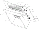
FIG. 1 is a schematic rear side view of the present invention;
FIG. 2 is a schematic front side view of the present invention;
FIG. 3 is a schematic view of a part of the anti-winding device of the present invention.
Wherein: 1. a water-blocking plate; 2. installing a side plate; 3. a rotating drum; 4. shifting the blades; 5. a barrier rail; 6. moving the guide rod; 7. a submersible motor; 8. positioning the side plate; 9. a hydraulic column; 10. a diversion trench; 11. a waste collection tank; 12. cleaning the push plate; 13. rotating the belt pulley; 14. a drive belt; 15. positioning the supporting rod; 16. a lower positioning swivel; 17. and an upper positioning swivel.
Detailed Description
The technical solutions in the embodiments of the present invention will be clearly and completely described below with reference to the drawings in the embodiments of the present invention, and it is obvious that the described embodiments are only a part of the embodiments of the present invention, and not all of the embodiments. All other embodiments, which can be derived by a person skilled in the art from the embodiments given herein without making any creative effort, shall fall within the protection scope of the present invention.
Referring to fig. 1-3, the utility model provides a grid for sewage treatment, comprising a water-blocking plate 1, a mounting side plate 2 is fixedly mounted on the rear side surface of the water-blocking plate 1, an anti-winding device is arranged on the inner side of the mounting side plate 2, a blocking railing 5 is fixedly mounted on the inner wall of the bottom of the mounting side plate 2, the upper end of the blocking railing 5 passes through the middle of an adjacent positioning support rod 15, a moving guide rod 6 is positioned on the outer side of a rotary drum 3, one end of the moving guide rod 6 far away from the blocking railing 5 extends to the front side of a waste collecting groove 11, the blocking and filtering of large garbage are carried out through the blocking railing 5 and the moving guide rod 6, the moving guide rod 6 is fixedly mounted at the top end of the blocking railing 5, a submersible motor 7 is fixedly mounted on the left side wall of the mounting side plate 2, a positioning side plate 8 is fixedly mounted on the rear side wall of the water-blocking plate 1 and positioned close to the top, a hydraulic column 9 is fixedly mounted on the left side wall of the positioning side plate 8, the output of hydraulic pressure post 9 runs through location curb plate 8, the rear side wall of installation curb plate 2 is located the position fixed mounting who leans on the bottom and has guiding gutter 10, the top fixed mounting of guiding gutter 10 has collection waste tank 11, the inside activity joint of collection waste tank 11 has clearance push pedal 12, collection waste tank 11 and clearance push pedal 12 are made by the filter plate that permeates water as the raw materials, make rivers directly see through collection waste tank 11 and clearance push pedal 12 and flow to the rear side, thereby make collection waste tank 11 inside rivers can not take place reverse flow and drive rubbish and break away from collection waste tank 11 inside, the output of hydraulic pressure post 9 and the left side wall fixed mounting of clearance push pedal 12, installation curb plate 2's left side wall is installed and is rotated belt pulley 13, drive belt 14 has been cup jointed in the outside of rotating belt pulley 13, submersible motor 7 is connected with rotation belt pulley 13 transmission through drive belt 14.
Further, the anti-winding device comprises a rotary drum 3, a toggle blade 4, a positioning support rod 15, a lower positioning rotary ring 16 and an upper positioning rotary ring 17, the rotary drum 3 is rotatably installed with the right side wall of the installation side plate 2 through a bearing, the right end of a rotary belt pulley 13 penetrates through the installation side plate 2 and is fixedly installed with the left end of the rotary drum 3, the positioning support rod 15 is fixedly installed with the outer wall of the rotary drum 3, the lower positioning rotary ring 16 is rotatably installed with the outer wall of the positioning support rod 15 through a bearing, the upper positioning rotary ring 17 is rotatably installed with the top end of the positioning support rod 15 through a bearing, a vortex spring is fixedly installed on the inner wall of the lower positioning rotary ring 16, the inner end of the vortex spring is fixedly installed with the outer wall of the positioning support rod 15, a second vortex spring is fixedly installed on the inner wall of the upper positioning rotary ring 17, the inner end of the second vortex spring is fixedly installed with the top end of the positioning support rod 15, so that the lower positioning rotary ring 16 and the upper positioning rotary ring 17 have an automatic resetting function after rotating, the outer walls of the toggle blades 4 and the upper positioning rotating ring 17 are fixedly installed, every two toggle blades 4 are in a group, the top of the second toggle blade 4 and the top of the lower positioning rotating ring 16 are fixedly installed, the included angle between the two toggle blades 4 in a static state is a right angle, impurities are pushed to move through the two toggle blades 4, the two toggle blades 4 can be closed and opened, the toggle blades 4 can approach each other to be in a parallel state under the impact force of water flow when the surface of the rotating drum 3 is close to the upper side when the surface of the rotating drum 4 rotates to the state that the surface of the rotating drum 3 is close to the lower side, the toggle blades 4 rotating to the surface of the rotating drum 3 keep a right-angle opening state, therefore, when the toggle blades 4 on the surface of the adjacent rotating drum 3 are dislocated, the toggle blades 4 close to the surface of the lower rotating drum 3 pass through the toggle blades 4 in an opening state close to the upper rotating drum 3, and rubbish pushed by two sides of the toggle blades 4 in a lower closing state is toggled to the upper side, thereby prevent that rubbish from twining at stirring blade 4 surface, thereby prevent to take place to block up and influence sewage treatment efficiency, through rotary drum 3, stir blade 4, location branch 15, lower location change 16 and last location change 17's cooperation is stirred rubbish and is upwards removed, and stir blade 4 and prevent to take place to twine through the mode of alternately stirring, submersible motor 7 drives through driving belt 14 and rotates belt pulley 13 and rotate, it drives rotary drum 3 and rotates to rotate belt pulley 13, rotary drum 3 is through location branch 15, lower location change 16 and last location change 17 drive stir blade 4 and rotate, upwards stir the clearance with the bold impurity that separation railing 5 filtered out, thereby prevent that rubbish accumulation from taking place to block up, it winds to have improved the circulation.
When in use, the grating is installed at a sewage inlet, the large impurities are filtered and blocked through the blocking railing 5, the submersible motor 7 is started, the submersible motor 7 drives the rotating belt pulley 13 to rotate through the transmission belt 14, the rotating belt pulley 13 drives the rotary drum 3 to rotate, the rotary drum 3 drives the positioning support rod 15 to rotate, the positioning support rod 15 drives the toggle blades 4 to rotate through the lower positioning rotary ring 16 and the upper positioning rotary ring 17, the toggle blades 4 can approach each other to be in a parallel state under the impact force of water flow when rotating to the surface of the rotary drum 3 to be close to the upper side, the toggle blades 4 rotating to the surface of the rotary drum 3 to be close to the lower side can keep a right-angle opening state, so that the toggle blades 4 on the surface of the adjacent rotary drum 3 are staggered, the toggle blades 4 on the surface of the lower side rotary drum 3 are closed to pass through the toggle blades 4 in an opening state on the surface of the upper side rotary drum 3, stir the rubbish that blade 4 both sides promoted of stirring blade 4 with the downside closure state through leaning on the upside rotary drum 3 state of opening and stir to the upside, thereby prevent that rubbish from twining on 4 surfaces of stirring blade, stir the clearance upwards through stirring blade 4 and filter 5 bulk impurities of crossing of separation railing 5, rubbish moves up to the outside of removing guide arm 6 along 5 surfaces of separation railing, last rubbish falls into the inside to collection waste chute 11, thereby prevent that the rubbish accumulation from taking place to block up, after 11 inside rubbish accumulations of collection waste chute are more, start hydraulic column 9, hydraulic column 9 promotes clearance push pedal 12 and promotes rubbish to push to discharge in the impurity discharge pipe of 11 right sides installations of collection waste chute to the right side.
Although embodiments of the present invention have been shown and described, it will be appreciated by those skilled in the art that changes, modifications, substitutions and alterations can be made in these embodiments without departing from the principles and spirit of the utility model, the scope of which is defined in the appended claims and their equivalents.
Claims (6)
1. The utility model provides a grid for sewage treatment, includes water-blocking plate (1), its characterized in that: the utility model discloses a hydraulic water-blocking board, including water-blocking board (1), baffle plate, hydraulic post (8), guide groove (10), baffle plate (1) trailing flank fixed mounting have installation curb plate (2), the inboard of installation curb plate (2) is provided with anti-winding device, the bottom inner wall fixed mounting of installation curb plate (2) has separation railing (5), the top fixed mounting of separation railing (5) has removal guide arm (6), the left side wall fixed mounting of installation curb plate (2) has submersible motor (7), the trailing flank of water-blocking board (1) is located the position fixed mounting who is close to the top and has location curb plate (8), the left side wall fixed mounting of location curb plate (8) has hydraulic column (9), the output of hydraulic column (9) runs through location curb plate (8), the trailing flank of installation curb plate (2) is located the position fixed mounting who leans on the bottom and has guide groove (10), the top fixed mounting of guide groove (10) has collection waste groove (11), the inside movable joint of collection useless groove (11) has clearance push pedal (12), the output of hydraulic pressure post (9) and the left side wall fixed mounting of clearance push pedal (12), the left side wall of installation curb plate (2) is installed and is rotated belt pulley (13), driving belt (14) have been cup jointed in the outside of rotating belt pulley (13), dive motor (7) are connected with rotation belt pulley (13) transmission through driving belt (14).
2. A grid for sewage treatment as claimed in claim 1, wherein: the anti-winding device comprises a rotary drum (3), a poking blade (4), a positioning support rod (15), a lower positioning rotary ring (16) and an upper positioning rotary ring (17), wherein the rotary drum (3) is rotatably installed with the right side wall of an installation side plate (2) through a bearing, the right end of a rotating belt pulley (13) penetrates through the installation side plate (2) and is fixedly installed with the left end of the rotary drum (3), the positioning support rod (15) is fixedly installed with the outer wall of the rotary drum (3), the lower positioning rotary ring (16) is rotatably installed with the outer wall of the positioning support rod (15) through a bearing, the upper positioning rotary ring (17) is rotatably installed with the top end of the positioning support rod (15) through a bearing, and the poking blade (4) is fixedly installed with the outer wall of the upper positioning rotary ring (17).
3. A grid for sewage treatment as claimed in claim 2, wherein: the inner wall of the lower positioning swivel (16) is fixedly provided with a vortex spring, the inner end of the vortex spring close to the outer wall of the positioning support rod (15) is fixedly arranged, the inner wall of the upper positioning swivel (17) is fixedly provided with a second vortex spring, and the inner end of the second vortex spring close to the top end of the positioning support rod (15) is fixedly arranged.
4. A grid for sewage treatment as claimed in claim 2, wherein: every two of the toggle blades (4) are in a group, the second toggle blade (4) is fixedly installed with the top of the lower positioning rotating ring (16), and an included angle between the two toggle blades (4) is a right angle in a static state.
5. A grille for sewage treatment as set forth in claim 2 wherein: the upper end that leans on of separation railing (5) is passed by adjacent location branch (15) centre, and removal guide arm (6) are located the outside of rotary drum (3), and the one end that separation railing (5) were kept away from in removal guide arm (6) extends the front side of collection groove (11).
6. A grid for sewage treatment as claimed in claim 1, wherein: the waste collecting groove (11) and the cleaning push plate (12) are both made of water-permeable filter plates.
Priority Applications (1)
| Application Number | Priority Date | Filing Date | Title |
|---|---|---|---|
| CN202122799746.1U CN216571846U (en) | 2021-11-12 | 2021-11-12 | Grid for sewage treatment |
Applications Claiming Priority (1)
| Application Number | Priority Date | Filing Date | Title |
|---|---|---|---|
| CN202122799746.1U CN216571846U (en) | 2021-11-12 | 2021-11-12 | Grid for sewage treatment |
Publications (1)
| Publication Number | Publication Date |
|---|---|
| CN216571846U true CN216571846U (en) | 2022-05-24 |
Family
ID=81645751
Family Applications (1)
| Application Number | Title | Priority Date | Filing Date |
|---|---|---|---|
| CN202122799746.1U Active CN216571846U (en) | 2021-11-12 | 2021-11-12 | Grid for sewage treatment |
Country Status (1)
| Country | Link |
|---|---|
| CN (1) | CN216571846U (en) |
Cited By (1)
| Publication number | Priority date | Publication date | Assignee | Title |
|---|---|---|---|---|
| CN117482631A (en) * | 2024-01-02 | 2024-02-02 | 北京禹涛环境工程有限公司 | Low-power hospital sewage treatment device |
-
2021
- 2021-11-12 CN CN202122799746.1U patent/CN216571846U/en active Active
Cited By (2)
| Publication number | Priority date | Publication date | Assignee | Title |
|---|---|---|---|---|
| CN117482631A (en) * | 2024-01-02 | 2024-02-02 | 北京禹涛环境工程有限公司 | Low-power hospital sewage treatment device |
| CN117482631B (en) * | 2024-01-02 | 2024-03-22 | 北京禹涛环境工程有限公司 | Low-power hospital sewage treatment device |
Similar Documents
| Publication | Publication Date | Title |
|---|---|---|
| CN113718922A (en) | Municipal administration underground drainage pipe automatically cleaning anti-clogging device | |
| CN111648536B (en) | Gutter structure of hyperboloid metal roofing | |
| CN208088351U (en) | A kind of anti-blocking row's of helping inspection shaft cap assemblies | |
| CN216571846U (en) | Grid for sewage treatment | |
| CN113526712B (en) | Sewage treatment equipment and method | |
| CN208792089U (en) | Road drainage system | |
| CN210737738U (en) | Town road drainage structures | |
| CN208815647U (en) | A kind of water pipeline for hydraulic engineering | |
| CN201574090U (en) | Cylindrical screen type fine grille | |
| CN215975023U (en) | Coarse grid for sewage treatment | |
| CN214914103U (en) | Anti-silting lifting device for inverted siphon | |
| CN209076230U (en) | A kind of dmp filter purification device | |
| CN218794484U (en) | Waste water filtering mechanism with anti-blocking structure | |
| CN216918804U (en) | Impurity removal and filtration system for vegetable washer | |
| CN216935053U (en) | Concrete waste water collection device | |
| CN216039054U (en) | Circulating filter device suitable for urban sewage treatment | |
| CN218106888U (en) | Sewage treatment equipment convenient to remove | |
| CN218011504U (en) | Rainwater purification device and rainwater purification treatment system | |
| CN218264247U (en) | Pipe network rain and sewage intelligent distribution device | |
| CN217596605U (en) | Cutting fluid recycling device for metal cutting | |
| CN215670602U (en) | Building roof rainwater collecting and treating device | |
| CN221118239U (en) | Drainage device for road bridge construction | |
| CN221513738U (en) | Waste water treatment device for waste mineral oil regeneration | |
| CN219128450U (en) | Resident domestic sewage treatment purifying mechanism | |
| CN217536880U (en) | Water conservancy floodgate device with filtering capability |
Legal Events
| Date | Code | Title | Description |
|---|---|---|---|
| GR01 | Patent grant | ||
| GR01 | Patent grant |