CN216569752U - Change-over valve and dust catcher - Google Patents
Change-over valve and dust catcher Download PDFInfo
- Publication number
- CN216569752U CN216569752U CN202122636482.8U CN202122636482U CN216569752U CN 216569752 U CN216569752 U CN 216569752U CN 202122636482 U CN202122636482 U CN 202122636482U CN 216569752 U CN216569752 U CN 216569752U
- Authority
- CN
- China
- Prior art keywords
- duct
- air
- air inlet
- valve body
- valve
- Prior art date
- Legal status (The legal status is an assumption and is not a legal conclusion. Google has not performed a legal analysis and makes no representation as to the accuracy of the status listed.)
- Active
Links
Images

Abstract
The application discloses a change-over valve and a dust collector. The switching valve includes: the valve comprises a valve body, an internal air duct and a driving device, wherein the internal air duct and the driving device are arranged in the valve body; the valve body is connected with the casing of dust catcher, and the casing is equipped with the vent, is used for the air inlet duct of driven air inlet and is used for the exhaust duct of driven air-out, the vent is equipped with the filter core, the first end of interconnection exhaust duct with the vent is connected, the outside of interconnection exhaust duct with drive arrangement connects, so that drive arrangement drives the second end rotation of interconnection exhaust duct predetermines the angle, makes the second end connection of interconnection exhaust duct is in the air inlet duct just the external space of exhaust duct intercommunication, perhaps makes the second end connection of interconnection exhaust duct is in the exhaust duct just the external space of air inlet duct intercommunication. This application is solved dust catcher filter core deashing inconvenient technical problem among the correlation technique.
Description
Technical Field
The application relates to the technical field of electrical equipment, in particular to a change-over valve and a dust collector.
Background
Most filter elements of dust collectors on the market are often blocked by dust, so that suction force is influenced, and the filter elements need to be cleaned in time. Dust cleaning modes of a dust collector are generally divided into two types: one is water washing, and the steps are complicated and the experience is poor after the operation; the other type is to directly replace the filter element, which has large replacement frequency and much waste.
Aiming at the problem that dust removal of a filter element of a dust collector is inconvenient in the related art, an effective solution is not provided at present.
Disclosure of Invention
The main aim of this application is to provide a change-over valve and dust catcher to solve the inconvenient problem of dust catcher filter core deashing among the correlation technique.
In order to achieve the above object, in a first aspect, the present application provides a switch valve.
A changeover valve according to the present application comprises: the valve comprises a valve body, an internal connecting air channel and a driving device, wherein the internal connecting air channel and the driving device are arranged in the valve body;
the valve body is connected with the casing of dust catcher, and the casing is equipped with the vent, is used for the air inlet duct of driven air inlet and is used for the exhaust duct of driven air-out, the vent is equipped with the filter core, the first end of interconnection exhaust duct with the vent is connected, the outside of interconnection exhaust duct with drive arrangement connects, so that drive arrangement drives the second end rotation of interconnection exhaust duct predetermines the angle, makes the second end connection of interconnection exhaust duct is in the air inlet duct just the external space of exhaust duct intercommunication, perhaps makes the second end connection of interconnection exhaust duct is in the exhaust duct just the external space of air inlet duct intercommunication.
Optionally, the driving device includes a driving motor and a transmission gear, the driving motor is fixed inside the valve body, the transmission gear is sleeved on an output shaft of the driving motor, and a rotating tooth engaged with the transmission gear is arranged on the outer side of the internal connection air duct.
Optionally, still be equipped with the outer intercommunication wind channel that is used for communicateing external space on the valve body, work as the drive arrangement drive the second end rotation of interconnection wind channel predetermines the angle, makes the second end of interconnection wind channel is connected the air inlet duct just outer intercommunication wind channel with the air outlet duct intercommunication, perhaps makes the second end of interconnection wind channel is connected the air outlet duct just outer intercommunication wind channel with the air inlet duct intercommunication.
Optionally, one end of the valve body, which is far away from the vent, is provided with a first through hole and a second through hole, the first through hole is communicated with the air outlet duct, and the second through hole is communicated with the air inlet duct.
Optionally, a plurality of protection holes communicated with the external space are formed in the side wall of the valve body, and the external communication air duct is communicated with the protection holes.
Optionally, an outer space of the valve body located in the inner connecting ventilation duct constitutes the outer connecting ventilation duct.
Optionally, the internal connecting ventilation duct further comprises a sealing ring, and the sealing ring is sleeved at the second end of the internal connecting ventilation duct.
In a second aspect, the present application also provides a vacuum cleaner comprising the above-described switch valve.
Optionally, still include the dust absorption motor, the dust absorption motor is installed in the casing, the intake stack intercommunication the air inlet end of motor, the exhaust stack intercommunication the air-out end of motor.
Optionally, the switching valve is located in the housing and the protective aperture is provided on the housing.
Optionally, the casing is inside to be equipped with and to be used for supporting dust absorption motor's horizontal stupefied, so that dust absorption motor is located the middle part of casing and dust absorption motor's outer wall with form the ventilation gap between the inner wall of casing, the intake stack passes through the ventilation gap intercommunication dust absorption motor's air inlet end.
In an embodiment of the present application, there is provided a switching valve by providing: the valve comprises a valve body, an internal connecting air channel and a driving device, wherein the internal connecting air channel and the driving device are arranged in the valve body; the valve body is connected with the casing of dust catcher, and the casing is equipped with the vent, is used for the air inlet duct of driven air inlet and is used for the exhaust duct of driven air-out, the vent is equipped with the filter core, the first end of interconnection exhaust duct with the vent is connected, the outside of interconnection exhaust duct with drive arrangement connects, so that drive arrangement drives the second end rotation of interconnection exhaust duct predetermines the angle, makes the second end connection of interconnection exhaust duct is in the air inlet duct just the external space of exhaust duct intercommunication, perhaps makes the second end connection of interconnection exhaust duct is in the exhaust duct just the external space of air inlet duct intercommunication. Drive the valve body through drive arrangement, make the second end of interconnection ventiduct connect out wind channel or air inlet duct, thereby change the air current circulation direction in the interconnection ventiduct, the air current makes the air current of guaranteeing to flow in the air inlet duct through the filter core flow direction interconnection ventiduct that sets up at the vent promptly and is filtered, perhaps the air current passes through interconnection ventiduct flow direction filter core, thereby blow away the dust on the filter core, thereby realize the purpose of dust catcher filter core deashing, wherein, the deashing process of the dust catcher of using this change-over valve is very convenient, only need to drive the valve body and can realize. Thereby solving the problem of inconvenient dust removal of the filter element of the dust collector in the related technology.
Drawings
The accompanying drawings, which are incorporated in and constitute a part of this application, serve to provide a further understanding of the application and to enable other features, objects, and advantages of the application to be more apparent. The drawings and their description illustrate the embodiments of the invention and do not limit it. In the drawings:
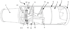
FIG. 1 is a partial cross-sectional view of a vacuum cleaner in a first state according to an embodiment of the present disclosure;
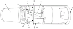
FIG. 2 is a partial cross-sectional view of a vacuum cleaner in a second state according to an embodiment of the present disclosure;
fig. 3 is a partial structural schematic view of a vacuum cleaner provided in an embodiment of the present application.
Detailed Description
In order to make the technical solutions better understood by those skilled in the art, the technical solutions in the embodiments of the present application will be clearly and completely described below with reference to the drawings in the embodiments of the present application, and it is obvious that the described embodiments are only partial embodiments of the present application, but not all embodiments. All other embodiments, which can be derived by a person skilled in the art from the embodiments given herein without making any creative effort, shall fall within the protection scope of the present application.
It should be noted that the terms "first," "second," and the like in the description and claims of this application and in the drawings described above are used for distinguishing between similar elements and not necessarily for describing a particular sequential or chronological order. It should be understood that the data so used may be interchanged under appropriate circumstances such that embodiments of the application described herein may be used. Furthermore, the terms "comprises," "comprising," and "having," and any variations thereof, are intended to cover a non-exclusive inclusion, such that a process, method, system, article, or apparatus that comprises a list of steps or elements is not necessarily limited to those steps or elements expressly listed, but may include other steps or elements not expressly listed or inherent to such process, method, article, or apparatus.
In this application, the terms "upper", "lower", "left", "right", "front", "rear", "top", "bottom", "inner", "outer", "middle", "vertical", "horizontal", "lateral", "longitudinal", and the like indicate orientations or positional relationships based on the orientations or positional relationships shown in the drawings. These terms are used primarily to better describe the present application and its embodiments, and are not used to limit the indicated devices, elements or components to a particular orientation or to be constructed and operated in a particular orientation.
Moreover, some of the above terms may be used to indicate other meanings besides the orientation or positional relationship, for example, the term "on" may also be used to indicate some kind of attachment or connection relationship in some cases. The specific meaning of these terms in this application will be understood by those of ordinary skill in the art as appropriate.
Furthermore, the terms "mounted," "disposed," "provided," "connected," "communicating," "secured," and the like are to be construed broadly. For example, "connected" may be a fixed connection, a detachable connection, or a unitary construction; can be a mechanical connection, or an electrical connection; may be directly connected, or indirectly connected through intervening media, or may be in internal communication between two devices, elements or components. The specific meaning of the above terms in the present application can be understood by those of ordinary skill in the art as appropriate.
In addition, the term "plurality" shall mean two as well as more than two.
It should be noted that the embodiments and features of the embodiments in the present application may be combined with each other without conflict. The present application will be described in detail below with reference to the embodiments with reference to the attached drawings.
As shown in fig. 1 to 3, an embodiment of the present application provides a switching valve including: the valve comprises a valve body 1, an internal connecting air channel 11 and a driving device, wherein the internal connecting air channel 11 and the driving device are arranged in the valve body 1;
valve body 1 is connected with casing 2 of dust catcher, and casing 2 is equipped with vent 21, is used for the air inlet duct 31 that receives the drive air inlet and is used for the exhaust duct 32 that receives the drive air-out, vent 21 is equipped with filter core 4, interconnection ventiduct 11 first end with vent 21 is connected, interconnection ventiduct 11 the outside with drive arrangement connects, so that drive arrangement drives the second end of interconnection ventiduct 11 rotates and predetermines the angle, makes interconnection ventiduct 11 second end is connected air inlet duct 31 just exhaust duct 32 intercommunication external space, perhaps makes interconnection ventiduct 11 second end is connected air outlet duct 32 just air inlet duct 31 intercommunication external space.
Concretely, drive valve body 1 through drive arrangement, make the second end of interconnection ventiduct 11 connect out wind channel 32 or air inlet duct 31, thereby change the air current circulation direction in interconnection ventiduct 11, the air current flows to interconnection ventiduct 11 through the filter core 4 that sets up at vent 21 promptly and makes the air current of guaranteeing to flow in air inlet duct 31 be through filterable, or the air current flows to filter core 4 through interconnection ventiduct 11, thereby blow away the dust on the filter core 4, thereby realize the purpose of the 4 deashing of dust catcher filter core, wherein, the deashing process of the dust catcher of using this change-over valve is very convenient, only need drive valve body 1 and can realize. Thereby solving the problem of inconvenient ash removal of the filter element 4 of the dust collector in the prior art.
As shown in fig. 1 and 2, the airflow direction of the vacuum cleaner using the switching valve is specifically as follows:
when the second end of the internal connecting ventilation duct 11 is connected to the air inlet duct 31 and the air outlet duct 32 is communicated with the external space, the airflow enters the internal connecting ventilation duct 11 through the filter element 4 and the vent 21, then enters the air inlet duct 31 driven by the driving device to enter air, and then enters the air outlet duct 32 driven by the driving device to exit air, so that the airflow flows to the external space through the air outlet duct 32;
when the second end of interconnection ventiduct 11 is connected in the exhaust passage 32 just when air inlet duct 31 communicates external space, the air current enters exhaust passage 32 through air inlet duct 31 of communicating external space, later, reentrants interconnection ventiduct 11, later, flows to vent 21 and filter core 4 through interconnection ventiduct 11.
Optionally, the driving device includes a driving motor 41 and a transmission gear 42, the driving motor 41 is fixed inside the valve body 1, the transmission gear 42 is sleeved on an output shaft of the driving motor 41, and a rotating tooth 111 engaged with the transmission gear 42 is arranged on the outer side of the inner connecting ventilation duct 11.
Specifically, drive arrangement includes driving motor 41 and drive gear 42, and the outside of interconnection ventiduct 11 be equipped with drive gear 42 engaged with rotatory tooth 111, like this, drive gear 42 through driving motor 41 and rotate, can drive with drive gear 42 engaged with rotatory tooth 111 is rotatory, and then makes the first end rotation of interconnection ventiduct 11 connect on vent 21, and make the second end connection of interconnection ventiduct 11 the air inlet duct 31 just air outlet 32 communicates external space, perhaps makes the second end connection of interconnection ventiduct 11 air outlet 32 just air inlet duct 31 communicates external space.
Specifically, still be equipped with the outer intercommunication wind channel 12 that is used for communicateing external space on the valve body 1, work as the drive arrangement drive the second end rotation of interconnection wind channel 11 predetermines the angle, makes the second end of interconnection wind channel 11 is connected the air inlet duct 31 just outer intercommunication wind channel 12 with air outlet duct 32 intercommunication, perhaps makes the second end of interconnection wind channel 11 is connected air outlet duct 32 just outer intercommunication wind channel 12 with air inlet duct 31 intercommunication.
One end, far away from the vent 21, of the valve body 1 is provided with a first through hole and a second through hole, the first through hole is communicated with the air outlet duct 32, and the second through hole is communicated with the air inlet duct 31.
Optionally, a cavity is further arranged in the valve body 1, the cavity is connected with an external space, and the air inlet duct 31 or the air outlet duct 32 is communicated with the cavity through a first through hole and a second through hole respectively. Thus, the chamber may replace the external communication duct 12.
Specifically, the valve body 1 is provided with a cavity, the internal connection ventilation duct 11 is located in the cavity, when the internal connection ventilation duct 11 is connected to the air inlet duct 31, a port of the air outlet duct 32 is exposed on the cavity, so that the air outlet duct 32 is connected to the cavity, so that the air outlet duct 32 is communicated with the external space, and when the internal connection ventilation duct 11 is connected to the air outlet duct 32, a port of the air inlet duct 31 is exposed on the cavity, so that the air inlet duct 31 is connected to the cavity, so that the air inlet duct 31 is communicated with the external space.
Optionally, a chamber in the valve body 1 located in the inner connecting ventilation duct 11 constitutes the outer connecting ventilation duct 12.
Wherein, by only rotating the second end of the internal connecting ventilation duct 11, the adjustment of the air flow direction in the internal connecting ventilation duct 11 can be realized.
Optionally, a plurality of protection holes 13 communicated with the external space are formed in the side wall of the valve body 1, and the external communication air duct 12 is communicated with the protection holes 13.
Wherein, the protection hole 13 is located between the cavity and the external space, so that the external particles with large volume can not enter the cavity through the protection hole 13, thereby avoiding the damage of parts caused by the entering of the particles with large volume into the cavity.
Optionally, the internal connecting device further comprises a sealing ring 7, and the sealing ring 7 is sleeved at the second end of the internal connecting ventilation channel 11.
Wherein, when the second end of the internal communicating air duct 11 is communicated with the first through hole or the second through hole, the sealing ring 7 seals the joint of the second end of the internal communicating air duct 11.
Based on the same technical concept, the application also provides a dust collector which comprises the change-over valve.
Specifically, this dust catcher still includes dust absorption motor 5, dust absorption motor installs in casing 2, intake stack 31 intercommunication the air inlet end of motor, exhaust stack 32 intercommunication the air-out end of dust absorption motor 5.
Alternatively, the switching valve is located in the housing 2, and the protection hole 13 is provided on the housing 2.
Optionally, be equipped with motor cavity 9 in casing 2, dust absorption motor 5 fixes in motor cavity 9, just dust absorption motor 5 with be equipped with ventilation gap between motor cavity 9's the inner wall, air inlet duct 31 with air-out duct 32 is located same one side of motor cavity 9, the relative air-out end in air inlet end of dust absorption motor 5 is close to air inlet duct 31, air inlet duct 31's first end with dust absorption motor 5's air inlet end intercommunication, air-out duct 32's first end is passed through ventilation gap intercommunication dust absorption motor 5's air-out end, air inlet duct 31's second end with air-out duct 32's second end all extends motor cavity 9.
Specifically, through dust absorption motor 5's outer wall with form ventilation gap between the inner wall of casing 2, then the exhaust passage 32 passes through the ventilation gap intercommunication dust absorption motor 5's air-out end promptly utilize dust absorption motor 5's outer wall with ventilation gap between the inner wall of casing 2 is as a dust absorption motor 5's ventilation duct for this dust catcher need not to set up the extra pipeline of air-out end of intercommunication dust absorption motor 5, and then has reduced casing 2's inner space, and then can reduce the size or the volume of dust catcher.
Optionally, the dust collector further comprises a bottom cover 8 and a sealing member, an opening is formed in one end, close to the air outlet end of the dust collection motor 5, of the housing 2, and the bottom cover 8 is packaged on the opening through the sealing member.
In particular, one side of the motor chamber 9 may be encapsulated by the bottom cover 8 and the sealing member.
For the encapsulation of the other side of the motor cavity 9, optionally, the size of the air outlet channel 32 is gradually increased towards the direction of the dust suction motor 5, and the outer wall of the air outlet channel 32 is encapsulated on the housing 2, so that the encapsulation of the other side of the motor cavity 9 is completed.
In addition, for forming a ventilation gap between the suction motor 5 and the inner wall of the motor chamber 9, at least the following two ways may be adopted:
first, optionally, the dust suction motor 5 is fixed on the bottom cover 8. That is, one side of the dust-collecting motor 5 is fixedly connected to the air inlet duct 31, and the other side of the dust-collecting motor 5 is fixedly connected to the bottom cover 8, thereby completing the fixing of the dust-collecting motor 5.
Secondly, optionally, the inner wall of the motor chamber 9 is provided with a transverse protruding ridge 22 for supporting the dust suction motor 5. Be used for supporting through the setting promptly dust absorption motor 5's horizontal stupefied 22 makes dust absorption motor 5's outer wall with form ventilation gap 6 between the inner wall of casing 2, then air-out channel 32 passes through ventilation gap 6 communicates dust absorption motor 5's air-out end.
The plurality of transverse protruding edges 22 are arranged, and the plurality of transverse protruding edges 22 are arranged around the dust collection motor 5 in a surrounding mode.
In an embodiment of the present application, there is provided a switching valve by providing: the valve comprises a valve body 1, an internal connecting air channel 11 and a driving device, wherein the internal connecting air channel 11 and the driving device are arranged in the valve body 1; valve body 1 is connected with the casing 2 of dust catcher, and casing 2 is equipped with vent 21, is used for the air inlet duct 31 of driven air inlet and is used for the exhaust duct 32 of driven air-out, vent 21 is equipped with filter core 4, the first end of interconnection air duct 11 with vent 21 is connected, the outside of interconnection air duct 11 with drive arrangement connects, so that drive arrangement drives the second end of interconnection air duct 11 rotates and predetermines the angle, makes the second end of interconnection air duct 11 is connected the air inlet duct 31 just the external space of exhaust duct 32 intercommunication, perhaps makes the second end of interconnection air duct 11 is connected the exhaust duct 32 just the external space of air inlet duct 31 intercommunication. Drive valve body 1 through drive arrangement for the second end of interconnection air duct 11 connects air outlet duct 32 or air inlet duct 31, thereby change the air current circulation direction in interconnection air duct 11, the air current makes the air current of guaranteeing to flow in air inlet duct 31 through the filter core 4 flow direction interconnection air duct 11 that sets up at vent 21 promptly, perhaps the air current flows to filter core 4 through interconnection air duct 11, thereby blow away the dust on the filter core 4, thereby realize the purpose of dust removal of dust catcher filter core 4, wherein, the dust removal process of the dust catcher of using this change-over valve is very convenient, only need drive valve body 1 and can realize. Thereby solving the problem of inconvenient ash removal of the filter element 4 of the dust collector in the prior art.
The above description is only a preferred embodiment of the present application and is not intended to limit the present application, and various modifications and changes may be made by those skilled in the art. Any modification, equivalent replacement, improvement and the like made within the spirit and principle of the present application shall be included in the protection scope of the present application.
Claims (10)
1. A diverter valve, comprising: the air valve comprises a valve body (1), an internal air duct (11) and a driving device, wherein the internal air duct and the driving device are arranged in the valve body (1);
valve body (1) is connected with casing (2) of dust catcher, and casing (2) are equipped with vent (21), are used for air inlet duct (31) that receives the drive air inlet and are used for air outlet duct (32) that receives the drive air-out, vent (21) are equipped with filter core (4), the first end of in-connection air duct (11) with vent (21) are connected, the outside of in-connection air duct (11) with drive arrangement connects, so that drive arrangement drives the second end of in-connection air duct (11) rotates preset angle, makes the second end of in-connection air duct (11) is connected air inlet duct (31) just air outlet duct (32) intercommunication external space, perhaps makes the second end of in-connection air duct (11) is connected air outlet duct (32) just air inlet duct (31) intercommunication external space.
2. The changeover valve as claimed in claim 1, wherein the driving means comprises a driving motor (41) and a transmission gear (42), the driving motor (41) is fixed inside the valve body (1), the transmission gear (42) is fitted around an output shaft of the driving motor (41), and a rotary gear (111) engaged with the transmission gear (42) is provided outside the internal air passage (11).
3. The switch valve as claimed in claim 2, wherein an external communication duct (12) for communicating with the external space is further disposed on the valve body (1), when the driving device drives the second end of the internal communication duct (11) to rotate by a predetermined angle, the second end of the internal communication duct (11) is connected to the air inlet duct (31) and the external communication duct (12) is communicated with the air outlet duct (32), or the second end of the internal communication duct (11) is connected to the air outlet duct (32) and the external communication duct (12) is communicated with the air inlet duct (31).
4. Switching valve as in claim 3, characterised in that the valve body (1) is provided with a first through opening and a second through opening at the end remote from the ventilation opening (21), the first through opening communicating with the air outlet duct (32) and the second through opening communicating with the air inlet duct (31).
5. Switching valve as in claim 4, characterised in that the valve body (1) is provided with a plurality of protection holes (13) on its side wall for communication with the outside space, and the external communication duct (12) communicates with the protection holes (13).
6. Switching valve as in claim 5, characterised in that the space outside the inner connecting duct (11) in the valve body (1) constitutes the outer connecting duct (12).
7. Switching valve as in claim 5, characterised in that it further comprises a sealing ring, which is fitted around the second end of the internal connecting air duct (11).
8. A vacuum cleaner comprising a changeover valve as claimed in any one of claims 1 to 7.
9. The vacuum cleaner as claimed in claim 8, further comprising a dust suction motor (5), wherein the dust suction motor (5) is installed in the housing (2), the air inlet duct (31) is communicated with an air inlet end of the motor, and the air outlet duct (32) is communicated with an air outlet end of the dust suction motor (5).
10. A vacuum cleaner, characterized in that it comprises a changeover valve as claimed in claim 5, which is located in the housing (2) and the protective aperture (13) is provided in the housing (2).
Priority Applications (2)
| Application Number | Priority Date | Filing Date | Title |
|---|---|---|---|
| CN202122636482.8U CN216569752U (en) | 2021-10-29 | 2021-10-29 | Change-over valve and dust catcher |
| PCT/CN2022/076397 WO2022247353A1 (en) | 2021-05-24 | 2022-02-16 | Change-over valve and vacuum cleaner |
Applications Claiming Priority (1)
| Application Number | Priority Date | Filing Date | Title |
|---|---|---|---|
| CN202122636482.8U CN216569752U (en) | 2021-10-29 | 2021-10-29 | Change-over valve and dust catcher |
Publications (1)
| Publication Number | Publication Date |
|---|---|
| CN216569752U true CN216569752U (en) | 2022-05-24 |
Family
ID=81642776
Family Applications (1)
| Application Number | Title | Priority Date | Filing Date |
|---|---|---|---|
| CN202122636482.8U Active CN216569752U (en) | 2021-05-24 | 2021-10-29 | Change-over valve and dust catcher |
Country Status (1)
| Country | Link |
|---|---|
| CN (1) | CN216569752U (en) |
-
2021
- 2021-10-29 CN CN202122636482.8U patent/CN216569752U/en active Active
Similar Documents
| Publication | Publication Date | Title |
|---|---|---|
| TW201500026A (en) | Dust collecting method and apparatus of self-propelled cleaning equipment | |
| CN107461807B (en) | Dust collector of air conditioner and have its air conditioner | |
| CN216569752U (en) | Change-over valve and dust catcher | |
| CN216569740U (en) | Vacuum cleaner | |
| CN106762722A (en) | Produce the air intake device and dust catcher or lampblack absorber with it of air stream | |
| CN217135618U (en) | Core switch that heat dispersion is good | |
| CN203542559U (en) | Dust collection accessory | |
| CN210300861U (en) | Dust collection box and cleaning robot | |
| CN116906347A (en) | Fan device of cleaning equipment, maintenance base station and cleaning robot system | |
| CN105126493A (en) | Air dust removal device for radiator and harvester | |
| CN215719601U (en) | High-pressure centrifugal fan is carried to material of two air-outs | |
| WO2022247353A1 (en) | Change-over valve and vacuum cleaner | |
| CN209789745U (en) | Scrubbing brush subassembly and robot of sweeping floor | |
| CN215738683U (en) | Change-over valve and dust catcher | |
| CN109171557B (en) | Dust collector | |
| CN210033887U (en) | Air suction device and range hood | |
| CN101581476B (en) | Wall-type air conditioner | |
| CN210520908U (en) | Cleaning device and dust collection box | |
| CN219166328U (en) | Motor assembly and cleaning equipment | |
| CN218934778U (en) | Fan device of cleaning equipment, maintenance base station and cleaning robot system | |
| CN215191290U (en) | Inhale and drag all-in-one | |
| CN215838666U (en) | Cleaning machine | |
| CN209362071U (en) | Big data filters deashing cabinet | |
| CN219814024U (en) | Dirt treatment module, base station and cleaning system | |
| CN219943914U (en) | Polar plate surface dust collector |
Legal Events
| Date | Code | Title | Description |
|---|---|---|---|
| GR01 | Patent grant | ||
| GR01 | Patent grant | ||
| TR01 | Transfer of patent right | ||
| TR01 | Transfer of patent right |
Effective date of registration: 20230710 Address after: 518000 Office Building 03, 5th Floor, Building B2, Xiandong Road, Xiandong Community, Xili Street, Nanshan District, Shenzhen City, Guangdong Province, China Patentee after: Shenzhen Yuanji Intelligent Technology Co.,Ltd. Patentee after: BEIJING VGO Co.,Ltd. Address before: 100083 Room 601, unit 5, building 11, Yueyuan, Xinghai Jiayuan community, Xihongmen Town, Daxing District, Beijing Patentee before: Cai Liang |