CN216554195U - Marine floating type wave power generation device based on pendulum oscillation principle - Google Patents
Marine floating type wave power generation device based on pendulum oscillation principle Download PDFInfo
- Publication number
- CN216554195U CN216554195U CN202123233085.2U CN202123233085U CN216554195U CN 216554195 U CN216554195 U CN 216554195U CN 202123233085 U CN202123233085 U CN 202123233085U CN 216554195 U CN216554195 U CN 216554195U
- Authority
- CN
- China
- Prior art keywords
- shell
- coil
- permanent magnet
- wave power
- balance ring
- Prior art date
- Legal status (The legal status is an assumption and is not a legal conclusion. Google has not performed a legal analysis and makes no representation as to the accuracy of the status listed.)
- Active
Links
Images


Classifications
-
- Y—GENERAL TAGGING OF NEW TECHNOLOGICAL DEVELOPMENTS; GENERAL TAGGING OF CROSS-SECTIONAL TECHNOLOGIES SPANNING OVER SEVERAL SECTIONS OF THE IPC; TECHNICAL SUBJECTS COVERED BY FORMER USPC CROSS-REFERENCE ART COLLECTIONS [XRACs] AND DIGESTS
- Y02—TECHNOLOGIES OR APPLICATIONS FOR MITIGATION OR ADAPTATION AGAINST CLIMATE CHANGE
- Y02E—REDUCTION OF GREENHOUSE GAS [GHG] EMISSIONS, RELATED TO ENERGY GENERATION, TRANSMISSION OR DISTRIBUTION
- Y02E10/00—Energy generation through renewable energy sources
- Y02E10/30—Energy from the sea, e.g. using wave energy or salinity gradient
Abstract
The utility model discloses a floating wave power generation device on the sea based on a pendulum oscillation principle, which comprises a shell, a permanent magnet sphere, a coil inlay, an omnidirectional balance ring and a power storage device, wherein the shell is provided with a permanent magnet sphere; the shell comprises an upper shell and a lower shell, the upper shell and the lower shell are in sealing butt joint and fixed through end flanges, and an oval or approximately oval cavity is formed in the shell; the permanent magnetic ball body is arranged in the shell, and the left end and the right end of the permanent magnetic ball body are fixed in the middle of the shell; the coil inlay is arranged in the permanent magnet sphere and is attached to the permanent magnet sphere; the coil inlay includes a coil body and a coil bundle; the omnidirectional balance ring comprises an outer balance ring, an inner balance ring and a rotating shaft; the omnidirectional balance ring is arranged inside the coil inlay; the electricity storage device comprises a rectifying circuit board and a battery. The utility model is suitable for the condition of large wind waves in the open sea, and the balance ring in the device senses the movement and continuously cuts magnetic lines of force, thereby generating continuous electric power to charge the battery.
Description
Technical Field
The utility model relates to a mechanical device for converting ocean wave energy into electric energy, in particular to a marine floating type wave power generation device based on a pendulum oscillation principle.
Background
Ocean waves are affected by factors such as sea wind and sea tide, waves with fluctuating heights are formed on the surface of seawater, huge renewable energy is stored in sea waves, and compared with energy obtained by burning petrochemical materials, the ocean waves have the advantages of being green, environment-friendly, inexhaustible and the like, and people are motivated to try to explore methods and devices for generating electricity by utilizing wave energy. The problems of high power generation cost, small power generation power and instability of the existing wave energy power generation are solved, and an efficient device capable of continuously converting wave energy into electric energy needs to be found. Meanwhile, the collection environment of wave energy is in river water or even seawater, so the requirement of the wave energy on corrosion resistance of the material is that the wave energy has good corrosion resistance on the premise of ensuring economy.
According to the utilization principle of wave energy, the conversion of wave energy into electric energy is generally divided into three stages, the first stage is wave energy capture, the second stage is an intermediate conversion and transmission system, and the third stage is a generator for outputting electric energy for load power. Because power attenuation exists between each stage, energy dissipation also exists, and the total acquisition efficiency is about 10-30%;
the wave energy conversion device comprises a floating device and an anchoring system, wherein the floating device floats on the sea surface and can move along with the movement of sea waves, and the anchoring system is usually arranged on the sea bed or on the shore and plays a role in fixing the floating device. One part needs to be fixed, and the other part moves relatively under the action of waves, so that power generation is realized by utilizing relative displacement, and the power generation device can be divided into an oscillating float type, an oscillating water column type, a raft type, a duck type, a wave-crossing type, a pushing and swinging type and the like according to the working principle, or can be divided into a pneumatic type, a hydraulic type, a mechanical type, a magnetic type and the like according to the energy transfer mode. All the devices need to be anchored and fixed to enable the devices to float on the water surface, and when the devices are deployed for a long time, sea creatures can grow on the devices.
SUMMERY OF THE UTILITY MODEL
The utility model aims to provide a marine floating type wave power generation device based on a pendulum oscillation principle. The device removes the device for anchoring and fixing, does not need to fix a part of the device, and reduces the capital investment of anchor chains and the like. Meanwhile, the device can be better suitable for the condition of large open sea stormy waves, and the balance ring in the device senses the movement and continuously cuts magnetic lines of force, so that continuous electric power is generated to charge the battery; the device is suitable for a water surface or underwater vehicle floating along with the wind waves, generates power by utilizing the fluctuation potential energy and the falling kinetic energy of the wind waves, and provides a power supply for a battery source for collecting information and sending and receiving information of the vehicle, so that the operation duration of the vehicle is prolonged, and the cruising operation capacity of the vehicle is enhanced.
In order to solve the technical problems, the utility model adopts the following technical scheme:
a marine floating type wave power generation device based on a pendulum oscillation principle comprises a shell, a permanent magnet sphere, a coil inlay, an omnidirectional balance ring and a power storage device;
the shell comprises an upper shell and a lower shell, the upper shell and the lower shell are in sealing butt joint and fixed through end flanges, and an oval or approximately oval cavity is formed inside the shell;
the permanent magnetic ball is arranged in the shell, and the left end and the right end of the permanent magnetic ball are fixed in the middle of the shell;
the coil inlay is arranged in the permanent magnet sphere and is fixedly attached to the permanent magnet sphere;
the coil inlay includes a coil body and a coil bundle;
the omnidirectional balance ring comprises an outer balance ring, an inner balance ring and a rotating shaft; the rotating shaft penetrates through the centers of the outer balancing ring and the inner balancing ring, and the rotating shaft, the outer balancing ring and the inner balancing ring are all rotatable connecting structures; the inner wall of the inner balancing ring is provided with a first permanent magnet and a second permanent magnet with opposite magnetic poles; a plurality of rotating balls are arranged on the circumference of the outer balancing ring and can lean against the coil inlay to slide;
the omnidirectional balance ring is arranged inside the coil inlay;
the electricity storage device comprises a rectifying circuit board and a battery, and the coil bundle is connected with the rectifying circuit board through a conducting wire.
In one embodiment, the bottom of the lower housing is provided with a counterweight such that the weight of the lower housing is 2-4 times the weight of the upper housing.
In one embodiment, a fin is provided on the upper case.
In one embodiment, the shell is made of a ceramic and resin composite material, and the surface of the shell is subjected to a smoothing treatment, such as polishing.
In one embodiment, the flanges of the upper and lower housings are bolted together.
In one embodiment, there are at least 3 rotating balls on the circumference of the outer balancing ring.
In one embodiment, the top of the upper shell is provided with a power device, and the power device is connected with the battery through a conducting wire.
In one embodiment, an electrical device is disposed outside the upper housing, and the battery is connected to the electrical device through a waterproof terminal.
In one embodiment, the electrical storage device is disposed at the bottom within the lower housing.
Any range recited herein is intended to include the endpoints and any number between the endpoints and any subrange subsumed therein or defined therein.
The starting materials of the present invention are commercially available, unless otherwise specified, and the equipment used in the present invention may be any equipment conventionally used in the art or may be any equipment known in the art.
Compared with the prior art, the utility model has the following beneficial effects:
1) the utility model adopts a simple mechanical structure, so that the mechanical motion of waves is directly combined with the change of the induced magnetic force, the electric energy is directly generated by utilizing the change of the magnetic force, and compared with other devices, the utility model reduces the energy conversion level, namely the capture and the conversion, thereby reducing the energy loss between the capture and the conversion and improving the conversion efficiency.
2) The utility model adopts the rotation principle of the rotating inertia balance ring, so that all the omnidirectional waves can be used for converting the wave energy into the electric energy, and the electric energy can be continuously converted in the restoring swing of the balance ring due to the existence of the omnidirectional rotating balance ring until the external environment is balanced, the wave height, the wavelength and other changes of the waves are basically not influenced, and the utility model can adapt to wider marine environment.
3) The utility model adopts the balance weight at the lower part of the shell, so that the whole stability is good, the anti-overturning performance is better, and the anti-storm capability is strong.
4) The shell of the utility model adopts ceramic and resin composite materials, has the composite characteristics of high strength and low density, and can effectively avoid the breeding and the attachment of marine organisms due to the adoption of smooth treatment on the surface.
5) The utility model can be integrated on underwater and water surface robots without power-driven motion fins in the open sea, and generates electricity under the action of wind waves, thereby effectively prolonging the service time of the battery and having beneficial influence on submarine topography exploration and scientific investigation.
Drawings
The following detailed description of embodiments of the utility model is provided in connection with the accompanying drawings
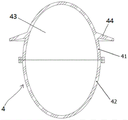
FIG. 1 is a schematic cross-sectional view of the present invention;
FIG. 2 is a schematic perspective, partially cross-sectional view of the present invention;
FIG. 3 is a schematic structural diagram of a permanent magnet sphere of the present invention;
FIG. 4 is a schematic diagram of the shape of the coil inlay and the permanent magnet sphere of the present invention;
FIG. 5 is a schematic cross-sectional view of a coil inlay of the present invention;
FIG. 6 is a schematic view of a coil inlay construction of the present invention;
FIG. 7 is a schematic diagram of an elevational structure of an omni-directional gimbal;
FIG. 8 is a schematic perspective view of an omni-directional gimbal;
FIG. 9 is a schematic structural view of the housing of the present invention;
FIG. 10 is a schematic structural view of an electric storage device according to the present invention;
fig. 11 is a schematic structural diagram of the float lamp.
Detailed Description
In order to more clearly illustrate the utility model, the utility model is further described below in connection with preferred embodiments. It is to be understood by persons skilled in the art that the following detailed description is illustrative and not restrictive, and is not to be taken as limiting the scope of the utility model.
It will be understood that when an element is referred to as being "secured to" or "disposed on" another element, it can be directly on the other element or be indirectly on the other element. When an element is referred to as being "connected to" another element, it can be directly connected to the other element or be indirectly connected to the other element.
It will be understood that the terms "length," "width," "upper," "lower," "front," "rear," "left," "right," "vertical," "horizontal," "top," "bottom," "inner," "outer," and the like, as used herein, refer to an orientation or positional relationship indicated in the drawings that is solely for the purpose of facilitating the description and simplifying the description, and do not indicate or imply that the device or element being referred to must have a particular orientation, be constructed and operated in a particular orientation, and is therefore not to be construed as limiting the utility model.
Furthermore, the terms "first", "second" and "first" are used for descriptive purposes only and are not to be construed as indicating or implying relative importance or implicitly indicating the number of technical features indicated. Thus, a feature defined as "first" or "second" may explicitly or implicitly include one or more of that feature. In the description of the present invention, "a plurality" means two or more unless specifically defined otherwise.
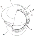
Referring to fig. 1, as one aspect of the present invention, the present invention relates to a floating wave power generation device on the sea based on pendulum oscillation principle, which comprises a housing 4, a permanent magnet sphere 1, a coil inlay 2, an omnidirectional balance ring 3 and a power storage device 5;
referring to fig. 9, the housing 4 includes an upper housing 41 and a lower housing 42, the upper housing 41 and the lower housing 42 are sealably abutted and fixed by end flanges, and an oval or approximately oval cavity 43 is formed inside the housing 4;
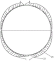
referring to fig. 3, the permanent magnet sphere 1 is arranged in the housing 4, and the left end and the right end of the permanent magnet sphere 1 are fixed in the middle of the housing 4;
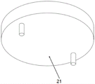
as shown in fig. 4-6, the coil inlay 2 is disposed inside the permanent magnet sphere 1, and is attached to the permanent magnet sphere 1; it can be understood that after the permanent magnetic sphere 1 and the coil inlay 2 are attached and fixed together, the relative position between the two will not change;
the coil inlay 2 comprises a coil body 21 and a coil bundle 22; it can be understood that the coil bundle is wound outside the coil body to form a power generation coil;
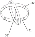
referring to fig. 7 and 8, the omni-directional gimbal 3 includes an outer gimbal 31, an inner gimbal 34, and a rotation shaft 33; the rotating shaft 33 passes through the centers of the outer balance ring 31 and the inner balance ring 34, and the rotating shaft 33 and the outer balance ring 31 and the inner balance ring 34 are both of a rotatable connecting structure; it can be understood that the rotatable connection mode can be realized by arranging rolling bearings at the joints of the two ends of the rotating shaft and the outer balancing ring and arranging the rolling bearings at the joints of the rotating shaft and the inner balancing ring;
a first permanent magnet 35 and a second permanent magnet 36 with opposite magnetic poles are arranged on the inner wall of the inner balancing ring 34;
a plurality of rotating balls 32 are arranged on the circumference of the outer balancing ring 31, and the rotating balls 32 can be propped against the permanent magnet ball body 1 to slide; by the arrangement, the omnidirectional balance ring 3 can freely slide in the coil inlay 2, and the outer balance ring 31 and the inner balance ring 34 can freely rotate around the rotating shaft 33;
the omnidirectional balance ring 3 is arranged inside the coil inlay 2;
referring to fig. 1 and 10, the electric storage device 5 includes a rectifier circuit board 51 and a battery 52, and the coil bundle 22 is connected to the rectifier circuit board 51 by a conductive wire.
In some embodiments, the bottom of the lower housing 42 is provided with a counterweight (not shown) such that the lower housing 42 weighs 2-4 times the weight of the upper housing. The anti-overturning wind power generation device has the advantages that the overall stability is good, the anti-overturning performance is good, and the anti-storm capability is strong.
In some embodiments, a fin 44 is disposed on the upper housing 41. For stability during the floating process of the present invention.
In some embodiments, the housing 4 is made of a ceramic and resin composite material, and the surface of the housing is subjected to a smoothing process, such as polishing. It can be understood that the shell has the composite characteristics of high strength and low density due to the adoption of the ceramic and resin composite material, and the breeding and the attachment of marine organisms can be effectively avoided due to the adoption of the smooth treatment on the surface of the shell.
In some embodiments, the flanges of the upper and lower housings 41, 42 are bolted together.
In some embodiments, there are at least 3 rotating balls on the circumference of the outer balancing ring 31.
In some embodiments, the top inside the upper case 41 is provided with a power consuming device 6, and the power consuming device 6 is connected with the battery 52 through a conductive wire. In the present invention, the powered device includes, but is not limited to, underwater and surface robots, surface vehicles, submersibles or floating lights, and the like. The float lamp 6 shown in fig. 1 and 11 is not intended to limit the utility model to a device for float power generation, but is merely a specific illustration or schematic of an application case. In the floating lamp implementation, the floating lamp 6 can be arranged inside the housing 4, and the upper housing 41 of the housing 4 needs to be a transparent partial design or by adding a window.
In some embodiments, an electrical device is provided outside the upper housing 41, and the battery is connected to the electrical device through a waterproof terminal. The battery power can be led out to other equipment needing charging in a mode of using the waterproof terminal.
In some embodiments, the electric storage device 5 is disposed at the bottom inside the lower case 42.
The use principle of the utility model is as follows:
when a wave first strikes the housing 4 of the device, the fins on the outer housing 4 are susceptible to continued wave impact, the upper part is deflected, and the inner gimbal ring 34 and the outer gimbal ring 31 of the gimbal ring 3 will try to remain stationary due to inertia. Since the housing 4, the permanent magnet ball ring 1 and the coil inlay 2 are connected and fixed, relative movement is generated with the balance ring 3, and the relative movement causes a magnetic field of the vector combination of the permanent magnets 35 and 36 on the balance ring and the permanent magnet ball ring 1 to change sharply, and a magnetic field change passing through the coil body 21 on the coil inlay 2 is formed, so that an induced current is induced in the coil body 21. The induced current flows through the coil bundle 22 to the rectifier circuit board 51 and the battery 52 through the combined connection, and the current rectifier circuit board 51 performs inversion and voltage regulation on the current to form stable and storable electric energy which is stored in the battery 52.
It should be understood that the above-described embodiments of the present invention are merely examples for clearly illustrating the present invention, and are not intended to limit the embodiments of the present invention. Other variations and modifications will be apparent to persons skilled in the art in light of the above description. Not all embodiments are exhaustive. All obvious changes and modifications which are obvious to the technical scheme of the utility model are covered by the protection scope of the utility model.
Claims (9)
1. The utility model provides a marine showy formula wave power generation set based on pendulum oscillation principle which characterized in that: the device comprises a shell, a permanent magnet sphere, a coil inlay, an omnidirectional balance ring and an electricity storage device;
the shell comprises an upper shell and a lower shell, the upper shell and the lower shell are in sealing butt joint and fixed through end flanges, and an oval or approximately oval cavity is formed inside the shell;
the permanent magnetic ball is arranged in the shell, and the left end and the right end of the permanent magnetic ball are fixed in the middle of the shell;
the coil inlay is arranged in the permanent magnet sphere and is attached to the permanent magnet sphere;
the coil inlay includes a coil body and a coil bundle;
the omnidirectional balance ring comprises an outer balance ring, an inner balance ring and a rotating shaft; the rotating shaft penetrates through the centers of the outer balancing ring and the inner balancing ring, and the rotating shaft, the outer balancing ring and the inner balancing ring are all rotatable connecting structures; the inner wall of the inner balancing ring is provided with a first permanent magnet and a second permanent magnet with opposite magnetic poles; a plurality of rotating balls are arranged on the circumference of the outer balancing ring and can lean against the permanent magnet ball body to slide;
the omnidirectional balance ring is arranged inside the coil inlay;
the electricity storage device comprises a rectifying circuit board and a battery, and the coil bundle is connected with the rectifying circuit board through a conducting wire.
2. The offshore floating wave power unit of claim 1, wherein: the bottom of the lower shell is provided with a balance weight, so that the weight of the lower shell is 2-4 times of that of the upper shell.
3. The offshore floating wave power unit of claim 1, wherein: the upper shell is provided with a fin-shaped body.
4. The offshore floating wave power unit of claim 1, wherein: the surface of the shell is smooth.
5. The offshore floating wave power unit of claim 1, wherein: the flanges of the upper shell and the lower shell are fixed together through bolts.
6. The offshore floating wave power unit of claim 1, wherein: at least 3 rotary balls are arranged on the circumference of the outer balancing ring.
7. The offshore floating wave power unit of claim 1, wherein: the top in the upper shell is provided with an electric device, and the electric device is connected with a battery through a conducting wire.
8. The offshore floating wave power unit of claim 1, wherein: an electric device is arranged outside the upper shell, and the battery is connected with the electric device through a waterproof terminal.
9. The offshore floating wave power unit of claim 1, wherein: the electricity storage device is arranged at the bottom in the lower shell.
Priority Applications (1)
| Application Number | Priority Date | Filing Date | Title |
|---|---|---|---|
| CN202123233085.2U CN216554195U (en) | 2021-12-21 | 2021-12-21 | Marine floating type wave power generation device based on pendulum oscillation principle |
Applications Claiming Priority (1)
| Application Number | Priority Date | Filing Date | Title |
|---|---|---|---|
| CN202123233085.2U CN216554195U (en) | 2021-12-21 | 2021-12-21 | Marine floating type wave power generation device based on pendulum oscillation principle |
Publications (1)
| Publication Number | Publication Date |
|---|---|
| CN216554195U true CN216554195U (en) | 2022-05-17 |
Family
ID=81544776
Family Applications (1)
| Application Number | Title | Priority Date | Filing Date |
|---|---|---|---|
| CN202123233085.2U Active CN216554195U (en) | 2021-12-21 | 2021-12-21 | Marine floating type wave power generation device based on pendulum oscillation principle |
Country Status (1)
| Country | Link |
|---|---|
| CN (1) | CN216554195U (en) |
-
2021
- 2021-12-21 CN CN202123233085.2U patent/CN216554195U/en active Active
Similar Documents
| Publication | Publication Date | Title |
|---|---|---|
| US8823196B1 (en) | Apparatus of wave generators and a mooring system to generate electricity | |
| CN112814829B (en) | Point absorption type wave energy power generation device | |
| CN105626363A (en) | Multi-dimensional single-buoy type wave energy converting device | |
| CN107288808B (en) | Wave energy and solar energy complementary drifting buoy self-power device | |
| CN201363232Y (en) | Wave power generation device | |
| CN210074995U (en) | Raft type wave energy electromagnetic induction power generation device | |
| CN107725258B (en) | Wave power unit, wave-power device and wave-activated power generation unit | |
| CN102878005B (en) | Pneumatic rubber bellows sea wave energy electromotor | |
| JP2014522933A5 (en) | ||
| TWM345135U (en) | Buoyancy type wind power generator | |
| CN101309041B (en) | Swinging type wave energy fluid metal magnetohydrodynamic electricity generation float tube | |
| CN114320720A (en) | Marine floating type wave power generation device based on pendulum oscillation principle | |
| CN114151263B (en) | Wave energy-light energy hybrid power generation device | |
| CN105763022B (en) | Ray formula metal magnetic fluid generating device and electricity-generating method | |
| CN106884756B (en) | Seawater surge can comprehensively utilize generating set with the tide energy of flow | |
| CN216554195U (en) | Marine floating type wave power generation device based on pendulum oscillation principle | |
| CN107747527A (en) | Wave-activated power generation unit and wave power unit, wave-power device | |
| KR200186257Y1 (en) | A generator using force of wave | |
| CN112319703B (en) | Floating type navigation mark lamp powered by sea energy | |
| CN209818199U (en) | Heaving type wave power generation device based on floating breakwater | |
| WO2019019071A1 (en) | Multi-purpose device for generating power by means of vibration induced by vertical vortex | |
| CN209105173U (en) | A kind of hidden extra long life sea test platform | |
| CN209385279U (en) | A kind of float type dielectric elastomer wave energy generator | |
| CN111779617A (en) | Tidal wave energy power generation system | |
| CN101344061B (en) | Suspending type wind wave generating station |
Legal Events
| Date | Code | Title | Description |
|---|---|---|---|
| GR01 | Patent grant | ||
| GR01 | Patent grant |