CN216503763U - Lathe with waste cleaning mechanism - Google Patents
Lathe with waste cleaning mechanism Download PDFInfo
- Publication number
- CN216503763U CN216503763U CN202122677285.0U CN202122677285U CN216503763U CN 216503763 U CN216503763 U CN 216503763U CN 202122677285 U CN202122677285 U CN 202122677285U CN 216503763 U CN216503763 U CN 216503763U
- Authority
- CN
- China
- Prior art keywords
- shaped cavity
- lathe
- base
- outlet end
- accordance
- Prior art date
- Legal status (The legal status is an assumption and is not a legal conclusion. Google has not performed a legal analysis and makes no representation as to the accuracy of the status listed.)
- Active
Links
Images


Landscapes
- Cleaning In General (AREA)
Abstract
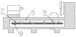
The utility model discloses a lathe with a waste cleaning mechanism, which comprises a lathe body, wherein a base is arranged below the lathe body, an L-shaped cavity is arranged in the base, a cleaning mechanism is arranged at an outlet end in the L-shaped cavity, a blanking groove is arranged at the outlet end of the L-shaped cavity on the base, an auger shaft is arranged in the blanking groove, and one end of the blanking groove is connected with a waste box; a photoelectric sensor is arranged at the outlet end of the L-shaped cavity; according to the utility model, the height information of the waste can be acquired by the photoelectric sensor, so that the cleaning mechanism is controlled to clean the waste accumulated in the L-shaped cavity into the blanking groove, and then the waste is transported into the fertilizer box by the auger shaft, so that the manual operation is reduced, and the working efficiency is improved.
Description
Technical Field
The utility model relates to the technical field of machining, in particular to a lathe with a waste cleaning mechanism.
Background
The lathe is one of the widely used machine tools at present, and is mainly used for cutting and processing inner and outer cylindrical surfaces of shaft parts or disc parts, inner and outer conical surfaces with any taper angle, inner and outer curved surfaces of complex rotation, cylinders, conical threads and the like, and can perform grooving, drilling, reaming, boring and the like.
Lathe on the market is of a great variety now, can satisfy people's user demand basically, but current lathe is generally cleared up through the manual work after work piece processing is accomplished, and not only the clearance degree of difficulty is great, and the cleanliness is relatively poor moreover, has increased staff's working strength, and current lathe needs artifical the collection when the piece of discharging more, has brought inconvenience for staff's use.
SUMMERY OF THE UTILITY MODEL
Aiming at the defects in the prior art, the utility model provides a lathe with a waste cleaning mechanism.
The utility model is realized by the following technical scheme:
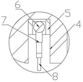
the utility model provides a take lathe of waste material clearance mechanism, includes lathe body, lathe body's below is equipped with base, its characterized in that: the automatic feeding device is characterized in that a diversion trench is arranged on the base, an L-shaped cavity is arranged in the base, the inlet end of the L-shaped cavity is connected with the diversion trench, the outlet end of the L-shaped cavity is positioned on one side of the base, a blanking groove is arranged at the outlet end of the L-shaped cavity on the base, an auger shaft is arranged in the blanking groove, and one end of the blanking groove is connected with a waste material box; the cleaning mechanism is arranged at the outlet end of the L-shaped cavity and comprises a mounting groove, a driving box, a rotating shaft, an elastic telescopic rod and a brush, the mounting groove is formed in the outlet end of the L-shaped cavity in the base, the driving box is slidably mounted in the mounting groove, the rotating shaft is rotatably connected in the driving box, and the rotating shaft is connected with the brush through the elastic telescopic rod; and a photoelectric sensor is arranged at the outlet end of the L-shaped cavity.
Preferably, the lateral wall of mounting groove is equipped with the spout, is equipped with the slider with spout matched with on the drive box, and the drive box passes through slider and spout slidable mounting in the mounting groove.
Preferably, the rotating shaft and the auger shaft are driven by a speed reducer.
Preferably, the cross-sectional shape of the flow guide groove is funnel-shaped.
Preferably, the bottom of the charging chute is an arc surface matched with the auger shaft.
Preferably, the outlet end of the L-shaped cavity is provided with a protective cover matched with the charging chute.
Preferably, the corners of the L-shaped cavity are rounded.
The utility model has the beneficial effects that: the photoelectric sensor is arranged at the outlet end of the L-shaped cavity, when waste at the outlet end of the L-shaped cavity is accumulated to a certain height, the cleaning mechanism can be controlled to clean the scraps into the blanking groove according to information collected by the photoelectric sensor, and the auger shaft in the blanking groove can convey the scraps into the waste box.
Drawings
In order to more clearly illustrate the detailed description of the utility model or the technical solutions in the prior art, the drawings that are needed in the detailed description of the utility model or the prior art will be briefly described below. Throughout the drawings, like elements or portions are generally identified by like reference numerals. In the drawings, elements or portions are not necessarily drawn to scale.
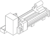
Fig. 1 is an axial view of the present invention.
Fig. 2 is an axial view of the present invention.
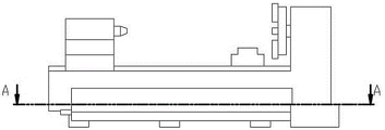
Fig. 3 is a front view of the present invention.
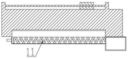
Fig. 4 is a sectional view taken along the line a of fig. 3.
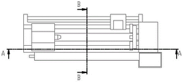
Fig. 5 is a top view of the present invention.
Fig. 6 is a sectional view taken along the line a in fig. 5.
Fig. 7 is a sectional view taken along line B of fig. 5.
Fig. 8 is a partially enlarged view of the bitmap 7.
In the attached drawing, the device comprises a base 1, a base 2, a diversion trench 3, an L-shaped cavity 4, a mounting groove 5, a driving box 6, a rotating shaft 7, an elastic telescopic rod 8, a brush 9, a sliding groove 10, a blanking groove 11, a packing auger shaft 12, a waste box 13, a protective cover 14 and a photoelectric sensor.
Detailed Description
In order to make the aforementioned objects, features and advantages of the present invention comprehensible, embodiments accompanied with figures are described in detail below. In the following description, numerous specific details are set forth in order to provide a thorough understanding of the present invention. This invention may, however, be embodied in many different forms and should not be construed as limited to the embodiments set forth herein.
It will be understood that when an element is referred to as being "secured to" another element, it can be directly on the other element or intervening elements may also be present. When an element is referred to as being "connected" to another element, it can be directly connected to the other element or intervening elements may also be present.
For ease of description, spatially relative terms, such as "upper," "lower," "left," "right," and the like, may be used herein to describe one element or feature's relationship to another element or feature as illustrated in the figures. It will be understood that the spatial terms are intended to encompass different orientations of the device in use or operation in addition to the orientation depicted in the figures. For example, if the device in the figures is turned over, elements described as "below" other elements or features would then be oriented "above" the other elements or features. Thus, the exemplary term "lower" can encompass both an upper and a lower orientation.
Unless defined otherwise, all technical and scientific terms used herein have the same meaning as commonly understood by one of ordinary skill in the art to which this invention belongs. The terminology used in the description of the utility model herein is for the purpose of describing particular embodiments only and is not intended to be limiting of the utility model. As used herein, the term "and/or" includes any and all combinations of one or more of the associated listed items.
The utility model is described in detail below with reference to the attached drawing figures: the lathe with the waste cleaning mechanism comprises a lathe body, wherein a base 1 is arranged below the lathe body, a diversion trench 2 is arranged on the base 1, the cross section of the diversion trench 2 is funnel-shaped, an L-shaped cavity 3 is arranged in the base 1, the inlet end of the L-shaped cavity 3 is connected with the diversion trench 2, the outlet end of the L-shaped cavity 3 is positioned on one side of the base 1, a blanking groove 10 is arranged at the outlet end of the L-shaped cavity 3 on the base 1, an auger shaft 11 is arranged in the blanking groove 10, the bottom of the blanking groove 10 is an arc surface matched with the auger shaft 11, and one end of the blanking groove 10 is connected with a waste box 12; the cleaning mechanism is arranged at the outlet end of the L-shaped cavity 3 and comprises a mounting groove 4, a driving box 5, a rotating shaft 6, an elastic telescopic rod 7 and a brush 8, the mounting groove 4 is formed in the outlet end of the L-shaped cavity 3 in the base 1, the driving box 5 is slidably mounted in the mounting groove 4, the rotating shaft 6 is rotatably connected in the driving box 5, the rotating shaft 6 is connected with the brush 8 through the elastic telescopic rod 7, and the position of the brush 8 can be adjusted in a self-adaptive mode through the elastic telescopic rod 7; and a photoelectric sensor 14 is arranged at the outlet end of the L-shaped cavity 3.
The side wall of the mounting groove 4 is provided with a sliding groove 9, the driving box 5 is provided with a sliding block matched with the sliding groove 9, and the driving box 5 is slidably mounted in the mounting groove 4 through the sliding block and the sliding groove 9; the lifting of the driving box 5 can be driven by a hydraulic cylinder or an air cylinder.
The rotating shaft 6 and the auger shaft 11 are driven by a speed reducer.
The exit end of L type cavity 3 is equipped with the protection casing 13 with charging chute 10 matched with, and the corner of L type cavity 3 is the fillet structure.
The working principle of the utility model is as follows: the piece that the cutting produced can pile up to the exit end department of L type cavity 3 through guiding gutter 2 and L type cavity 3, when photoelectric sensor 14 detected the piece of 3 exit end departments of L type cavity and has reached the settlement height, drive box 5 descends, brush 8 rotates under the drive of pivot 6, sweep the piece into charging chute 10 in, auger shaft 11 in the charging chute 10 can transport the piece to waste material box 12 in, accomplish the collection of waste material, thereby the time of artifical clearance has been reduced by a wide margin.
Finally, it should be noted that: the above embodiments are only used to illustrate the technical solution of the present invention, and not to limit the same; while the utility model has been described in detail and with reference to the foregoing embodiments, it will be understood by those skilled in the art that: the technical solutions described in the foregoing embodiments may still be modified, or some or all of the technical features may be equivalently replaced; such modifications and substitutions do not depart from the spirit and scope of the present invention, and they should be construed as being included in the following claims and description.
Claims (7)
1. The utility model provides a take lathe of waste material clearance mechanism, includes lathe body, lathe body's below is equipped with base (1), its characterized in that: the automatic blanking machine is characterized in that a diversion trench (2) is formed in the base (1), an L-shaped cavity (3) is formed in the base (1), the inlet end of the L-shaped cavity (3) is connected with the diversion trench (2), the outlet end of the L-shaped cavity (3) is located on one side of the base (1), a blanking groove (10) is formed in the outlet end of the L-shaped cavity (3) in the base (1), an auger shaft (11) is arranged in the blanking groove (10), and one end of the blanking groove (10) is connected with a waste material box (12); the cleaning mechanism is arranged at the outlet end of the L-shaped cavity (3) and comprises a mounting groove (4), a driving box (5), a rotating shaft (6), an elastic telescopic rod (7) and a brush (8), the mounting groove (4) is arranged at the outlet end of the L-shaped cavity (3) in the base (1), the driving box (5) is arranged in the mounting groove (4) in a sliding mode, the rotating shaft (6) is connected in the driving box (5) in a rotating mode, and the rotating shaft (6) is connected with the brush (8) through the elastic telescopic rod (7); and a photoelectric sensor (14) is arranged at the outlet end of the L-shaped cavity (3).
2. A lathe with a scrap removal mechanism in accordance with claim 1 wherein: the lateral wall of mounting groove (4) is equipped with spout (9), is equipped with the slider with spout (9) matched with on drive box (5), and drive box (5) pass through slider and spout (9) slidable mounting in mounting groove (4).
3. A lathe with a scrap removal mechanism in accordance with claim 1 wherein: the rotating shaft (6) and the auger shaft (11) are driven by a speed reducer.
4. A lathe with a scrap removal mechanism in accordance with claim 1 wherein: the cross section of the flow guide groove (2) is funnel-shaped.
5. A lathe with a scrap removal mechanism in accordance with claim 1 wherein: the bottom of the charging chute (10) is an arc surface matched with the auger shaft (11).
6. A lathe with a scrap removal mechanism in accordance with claim 1 wherein: and a protective cover (13) matched with the charging chute (10) is arranged at the outlet end of the L-shaped cavity (3).
7. A lathe with a scrap removal mechanism in accordance with claim 1 wherein: the corner of the L-shaped cavity (3) is of a fillet structure.
Priority Applications (1)
| Application Number | Priority Date | Filing Date | Title |
|---|---|---|---|
| CN202122677285.0U CN216503763U (en) | 2021-11-04 | 2021-11-04 | Lathe with waste cleaning mechanism |
Applications Claiming Priority (1)
| Application Number | Priority Date | Filing Date | Title |
|---|---|---|---|
| CN202122677285.0U CN216503763U (en) | 2021-11-04 | 2021-11-04 | Lathe with waste cleaning mechanism |
Publications (1)
| Publication Number | Publication Date |
|---|---|
| CN216503763U true CN216503763U (en) | 2022-05-13 |
Family
ID=81526025
Family Applications (1)
| Application Number | Title | Priority Date | Filing Date |
|---|---|---|---|
| CN202122677285.0U Active CN216503763U (en) | 2021-11-04 | 2021-11-04 | Lathe with waste cleaning mechanism |
Country Status (1)
| Country | Link |
|---|---|
| CN (1) | CN216503763U (en) |
-
2021
- 2021-11-04 CN CN202122677285.0U patent/CN216503763U/en active Active
Similar Documents
| Publication | Publication Date | Title |
|---|---|---|
| CN210756361U (en) | Cutting and grinding machining center equipment with gantry driving mechanism | |
| CN211252012U (en) | Self-cleaning formula engraver | |
| CN216503763U (en) | Lathe with waste cleaning mechanism | |
| CN206900751U (en) | A kind of lathe solid waste concentrates sealed in unit | |
| CN210966994U (en) | Numerical control lathe convenient to clearance waste material | |
| CN206550748U (en) | A kind of Digit Control Machine Tool debris collection device | |
| CN218397194U (en) | Numerical control lathe with waste collecting device for metal parts | |
| CN208841011U (en) | A kind of automation chip removal system of polar coordinates drilling machine | |
| CN215998735U (en) | Lathe garbage collection device | |
| CN210435816U (en) | Novel metal debris is collected for processing of digit control machine tool clout device | |
| CN213673127U (en) | Sweeps cleaning device of numerical control lathe | |
| CN211614320U (en) | Machine tool with dust collection structure and angle adjustment function | |
| CN210633351U (en) | Waste collecting device for numerical control machine tool | |
| CN212601266U (en) | High-precision outer circle grinding machine with chip cleaning structure | |
| CN209440358U (en) | A kind of timber window processing vertical milling machine | |
| CN210523840U (en) | Numerical control lathe of easy chip removal | |
| CN210648660U (en) | Drilling machine garbage collection device | |
| CN211842377U (en) | Timber cutting machine with garbage collection function | |
| CN208132542U (en) | A kind of slug collection platform of rocker arm drilling machine | |
| CN209190254U (en) | A kind of milling machine | |
| CN208467898U (en) | A kind of lathe cuts recyclable device with iron | |
| CN208214343U (en) | It is a kind of convenient for collect processing after part lathe | |
| CN219901352U (en) | Lathe outer protective cover | |
| CN213225323U (en) | Lightweight high-rigidity gantry milling center platform | |
| CN213164361U (en) | Dust collecting device suitable for digit control machine tool |
Legal Events
| Date | Code | Title | Description |
|---|---|---|---|
| GR01 | Patent grant | ||
| GR01 | Patent grant |