CN216480055U - High-precision humidity detector - Google Patents
High-precision humidity detector Download PDFInfo
- Publication number
- CN216480055U CN216480055U CN202122470268.XU CN202122470268U CN216480055U CN 216480055 U CN216480055 U CN 216480055U CN 202122470268 U CN202122470268 U CN 202122470268U CN 216480055 U CN216480055 U CN 216480055U
- Authority
- CN
- China
- Prior art keywords
- rack
- clamping plate
- humidity detector
- detector body
- lead screw
- Prior art date
- Legal status (The legal status is an assumption and is not a legal conclusion. Google has not performed a legal analysis and makes no representation as to the accuracy of the status listed.)
- Active
Links
Images


Abstract
The utility model relates to the technical field of humidity detectors, and particularly discloses a high-precision humidity detector which comprises a humidity detector body and a placing frame, wherein the humidity detector body is arranged on the placing frame, a first clamping plate and a second clamping plate are respectively arranged on two sides of the humidity detector body, a horizontally arranged rack is connected to one side of the first clamping plate, a gear is meshed and connected below the rack, a through hole connected with the rack is arranged in a penetrating manner on one side of the placing frame, a connecting column is horizontally arranged on the inner wall of the other side of the placing frame, one end of the connecting column is connected with one side of the second clamping plate, a connecting block is horizontally arranged on one side of the placing frame, the rack is driven to move by the rotation of the gear, the first clamping plate is driven to move, and the humidity detector body is clamped, the convenience brings convenience to the detection work carried out by the humidity detector body.
Description
Technical Field
The utility model relates to the technical field of humidity detectors, in particular to a high-precision humidity detector.
Background
The humidity detector is a measuring instrument used for detecting the humidity of air and various gases, and when the existing humidity detector is used, the existing humidity detector is held by a worker for detection, so that the labor intensity is increased, the equipment is easy to shake, the detection precision is reduced, and the positions with different heights are inconvenient to adjust by the worker, so that inconvenience is brought to detection work.
SUMMERY OF THE UTILITY MODEL
The utility model aims to provide a high-precision humidity detector to solve the problems in the background technology.
In order to achieve the purpose, the utility model provides the following technical scheme: a high-precision humidity detector comprises a humidity detector body and a placing rack, wherein the humidity detector body is arranged on the placing rack, a first clamping plate and a second clamping plate are respectively arranged at two sides of the humidity detector body, one side of the first clamping plate is connected with a rack which is horizontally arranged, a gear is engaged and connected below the rack, a through hole connected with the rack is arranged at one side of the placing rack in a penetrating way, a connecting column is horizontally arranged on the inner wall of the other side of the placing rack, one end of the connecting column is connected with one side of the second clamping plate, one side of the placing frame is horizontally provided with a connecting block, one end of the connecting block is connected with one side of the nut, the nut is connected on the lead screw of vertical setting, the lead screw sets up in the installing frame, the vertical spout that is provided with of installing frame one side, spout and connecting block sliding connection.
Preferably, the outer wall of one end of the placing rack is provided with a mounting rack, and the mounting rack is provided with a rotating rod connected with the gear.
Preferably, the bottom both sides of installing frame all are provided with the link, and the link is L shape structure, the link sets up on the base, and the bottom of base is connected with a plurality of gyro wheels.
Preferably, the top of installing frame is connected with the connecting axle of vertical setting, the top of lead screw is provided with the connecting hole that is connected with the connecting axle, the equal level in top of connecting axle and lead screw is run through and is provided with the screw that is connected with connecting bolt.
Preferably, the bottom of lead screw is connected with the axis of rotation, the bottom of installing frame is run through and is provided with the shaft hole that is connected with the axis of rotation, and axis of rotation one end is connected with the rolling disc.
Compared with the prior art, the utility model has the beneficial effects that: through putting the moisture detector body on the rack, through the rotation of gear, drive the rack and remove, drive first clamp plate and remove, press from both sides the moisture detector body tightly, the detection work that the convenience goes on the moisture detector body facilitates to improve the precision that detects, the rotation of lead screw, nut drive connecting block slide in the spout, highly adjust the moisture detector body, offer convenience for the use.
Drawings
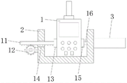
FIG. 1 is a schematic view of the overall structure of the present invention;
FIG. 2 is a schematic view of the humidity detector body and the placement frame of the present invention;
fig. 3 is an enlarged schematic view of a in fig. 1.
In the figure: 1. a moisture detector body; 2. placing a rack; 3. connecting blocks; 4. a nut; 5. a screw rod; 6. installing a frame; 7. a chute; 8. a connecting frame; 9. a rotating shaft; 10. a base; 11. a rack; 12. a gear; 13. a first clamping plate; 14. a through hole; 15. a second clamping plate; 16. connecting columns; 17. a connecting shaft; 18. connecting holes; 19. and connecting the bolts.
Detailed Description
The technical solutions in the embodiments of the present invention will be clearly and completely described below with reference to the drawings in the embodiments of the present invention, and it is obvious that the described embodiments are only a part of the embodiments of the present invention, and not all of the embodiments. All other embodiments, which can be derived by a person skilled in the art from the embodiments given herein without making any creative effort, shall fall within the protection scope of the present invention.
In the description of the present invention, it should be noted that the terms "vertical", "upper", "lower", "horizontal", and the like indicate orientations or positional relationships based on those shown in the drawings, and are only for convenience of describing the present invention and simplifying the description, but do not indicate or imply that the referred device or element must have a specific orientation, be constructed in a specific orientation, and be operated, and thus, should not be construed as limiting the present invention.
In the description of the present invention, it should also be noted that, unless otherwise explicitly specified or limited, the terms "disposed," "mounted," "connected," and "connected" are to be construed broadly and may, for example, be fixedly connected, detachably connected, or integrally connected; can be mechanically or electrically connected; they may be connected directly or indirectly through intervening media, or they may be interconnected between two elements. The specific meanings of the above terms in the present invention can be understood by those skilled in the art according to specific situations.
Referring to fig. 1-3, the present invention provides a technical solution: the utility model provides a high accuracy moisture detector, including moisture detector body 1 and rack 2, moisture detector body 1 sets up on rack 2, moisture detector body 1's both sides are provided with first clamp plate 13 and second clamp plate 15 respectively, rack 11 that first clamp plate 13 one side was connected with the level and sets up, rack 11's below meshing is connected with gear 12, 2 one side of rack runs through the through-hole 14 that is provided with and is connected with rack 11, rack 2's opposite side inner wall is improved level and is provided with spliced pole 16, spliced pole 16's one end is connected with one side of second clamp plate 15, 2 one side level of rack is provided with connecting block 3, one end of connecting block 3 is connected in one side of nut 4, nut 4 connects on the lead screw 5 of vertical setting, lead screw 5 sets up in installing frame 6, 6 one side is vertical to be provided with spout 7, spout 7 and 3 sliding connection of connecting block.
The outer wall of one end of the placing rack 2 is provided with a mounting rack, and a rotating rod connected with the gear 12 is arranged on the mounting rack.
The bottom both sides of installing frame 6 all are provided with link 8, and link 8 is L shape structure, and link 8 sets up on base 10, and the bottom of base 10 is connected with a plurality of gyro wheels.
The top of the mounting frame 6 is connected with a connecting shaft 17 which is vertically arranged, the top end of the screw rod 5 is provided with a connecting hole 18 which is connected with the connecting shaft 17, and the top ends of the connecting shaft 17 and the screw rod 5 are horizontally provided with screw holes which are connected with a connecting bolt 19 in a penetrating mode.
The bottom of lead screw 5 is connected with axis of rotation 9, and the bottom of installing frame 6 runs through and is provided with the shaft hole that is connected with axis of rotation 9, and 9 one ends of axis of rotation are connected with the rolling disc.
The working principle is as follows: during the use, lead screw 5 is installed in installing frame 6, connecting axle 17 is connected with connecting hole 18, then be connected connecting bolt 19 with the screw, be connected connecting axle 17 with the top of lead screw 5, through putting moisture meter body 1 on rack 2, the dwang drives gear 12 and rotates, it slides in through-hole 14 to drive rack 11, it removes to drive first clamp plate 13, press from both sides tightly moisture meter body 1, need examine time measuring, rotation through axis of rotation 9, it rotates to drive lead screw 5, nut 4 removes, it slides in spout 7 to drive connecting block 3, highly adjust moisture meter body 1, conveniently detect.
Although embodiments of the present invention have been shown and described, it will be appreciated by those skilled in the art that changes, modifications, substitutions and alterations can be made in these embodiments without departing from the principles and spirit of the utility model, the scope of which is defined in the appended claims and their equivalents.
Claims (5)
1. The utility model provides a high accuracy moisture detector, includes moisture detector body (1) and rack (2), its characterized in that: the humidity detector comprises a humidity detector body (1) arranged on a placing rack (2), wherein a first clamping plate (13) and a second clamping plate (15) are respectively arranged on two sides of the humidity detector body (1), a horizontally arranged rack (11) is connected to one side of the first clamping plate (13), a gear (12) is meshed and connected to the lower portion of the rack (11), a through hole (14) connected with the rack (11) is arranged on one side of the placing rack (2) in a penetrating mode, a connecting column (16) is horizontally arranged on the inner wall of the other side of the placing rack (2), one end of the connecting column (16) is connected to one side of the second clamping plate (15), a connecting block (3) is horizontally arranged on one side of the placing rack (2), one end of the connecting block (3) is connected to one side of a nut (4), and the nut (4) is connected to a vertically arranged screw rod (5), the lead screw (5) is arranged in the mounting frame (6), a sliding groove (7) is vertically arranged on one side of the mounting frame (6), and the sliding groove (7) is connected with the connecting block (3) in a sliding mode.
2. A high accuracy moisture meter according to claim 1, wherein: the outer wall of one end of the placing rack (2) is provided with a mounting rack, and a rotating rod connected with the gear (12) is arranged on the mounting rack.
3. A high accuracy moisture meter according to claim 1, wherein: the bottom both sides of installing frame (6) all are provided with link (8), and link (8) are L shape structure, link (8) set up on base (10), and the bottom of base (10) is connected with a plurality of gyro wheels.
4. A high accuracy moisture meter according to claim 1, wherein: the top of installing frame (6) is connected with connecting axle (17) of vertical setting, the top of lead screw (5) is provided with connecting hole (18) that are connected with connecting axle (17), the equal level in top of connecting axle (17) and lead screw (5) is run through and is provided with the screw that is connected with connecting bolt (19).
5. A high accuracy moisture meter according to claim 1, wherein: the bottom of lead screw (5) is connected with axis of rotation (9), the bottom of installing frame (6) is run through and is provided with the shaft hole that is connected with axis of rotation (9), and axis of rotation (9) one end is connected with the rolling disc.
Priority Applications (1)
| Application Number | Priority Date | Filing Date | Title |
|---|---|---|---|
| CN202122470268.XU CN216480055U (en) | 2021-10-13 | 2021-10-13 | High-precision humidity detector |
Applications Claiming Priority (1)
| Application Number | Priority Date | Filing Date | Title |
|---|---|---|---|
| CN202122470268.XU CN216480055U (en) | 2021-10-13 | 2021-10-13 | High-precision humidity detector |
Publications (1)
| Publication Number | Publication Date |
|---|---|
| CN216480055U true CN216480055U (en) | 2022-05-10 |
Family
ID=81440492
Family Applications (1)
| Application Number | Title | Priority Date | Filing Date |
|---|---|---|---|
| CN202122470268.XU Active CN216480055U (en) | 2021-10-13 | 2021-10-13 | High-precision humidity detector |
Country Status (1)
| Country | Link |
|---|---|
| CN (1) | CN216480055U (en) |
-
2021
- 2021-10-13 CN CN202122470268.XU patent/CN216480055U/en active Active
Similar Documents
| Publication | Publication Date | Title |
|---|---|---|
| CN217153568U (en) | Multi-angle leveling equipment for measuring surveying and mapping instrument | |
| CN216480055U (en) | High-precision humidity detector | |
| CN214097216U (en) | Pressure vessel nondestructive test device of convenient regulation | |
| CN208333468U (en) | For the support frame in tunnel top placement total station | |
| CN110954151A (en) | Multi-angle photoelectric sensor detection device | |
| CN112304226A (en) | Comprehensive detection tool for air filter support assembly | |
| CN211118499U (en) | Mobilizable environment measuring device for building monitoring | |
| CN208296707U (en) | A kind of equipment detecting steel size | |
| CN215492821U (en) | Concrete resiliometer with stop device | |
| CN112318454A (en) | Mobile phone tooling clamp adaptable to fixation in multiple test environments | |
| CN220602411U (en) | Template straightness measuring device that hangs down based on guiding ruler | |
| CN218765369U (en) | Automatic calibration device for vision sensor | |
| CN213238672U (en) | Hole site inspection smelting tool | |
| CN216558666U (en) | Standardized size diameter check out test set of pipeline production | |
| CN216524665U (en) | Multifunctional rotation tester | |
| CN220416755U (en) | Cable crane anchor ingot deformation measuring device | |
| CN215726359U (en) | Noise detection is with fixed frock | |
| CN212780034U (en) | Sampling device for soil detection | |
| CN215109489U (en) | Semi-closed screw compressor of carbon dioxide liquid cooling motor | |
| CN214224198U (en) | Device convenient to installation of case class environment humiture equipment | |
| CN220013388U (en) | Cable-shaped measuring device for catwalk of suspension bridge | |
| CN217030592U (en) | Fixing equipment for detecting instruments and meters | |
| CN213456409U (en) | Tester for on-site detection of compressive strength of cement mortar | |
| CN216954313U (en) | Automobile part height detection tool | |
| CN219675771U (en) | Dust sampling instrument for environment detection |
Legal Events
| Date | Code | Title | Description |
|---|---|---|---|
| GR01 | Patent grant | ||
| GR01 | Patent grant |